background image

Service

If the instrument fails, check the battery and replace as needed. Also check the probe as
previously described. If the instrument still does not work properly, service is required. For
factory service in the United States, call (toll-free) 800-426-9265 to describe the malfunction and
obtain an RMA number and shipping instructions prior to shipment. This number must be clearly
displayed on the exterior of the shipping carton.
Only parcels displaying an RMA number will be accepted. In Washington state, call
425-743 3171. Huntron is also accessible bye FAX at 425-743-1360, by e-mail at
[email protected], and on our Internet Home Page at http://www.huntron.com. Pack the
instrument securely in its original shipping container and ship it, postage paid, to Huntron
Instruments, Inc. at the address given in the front of this manual. Outside the United States,
contact your local distributor for service. Please include a description of the malfunction. An
instrument under warranty will be promptly repaired or replaced (at Huntron's option) and
returned at no charge. See the front of this manual for warranty terms. If the warranty has
lapsed, the instrument will be repaired and returned for a service fee. Contact Huntron for prices.

SPECIFICATIONS
Signal Source:


LOW range of a Huntron Tracker
open circuit voltage:<_>10 Volts peak
short circuit current:<_>132mA RMS

Frequency Response:

 50Hz to 2000Hz

Sensitivity:


Display can be adjusted to 100% with current flow caused by a 20ohm resistance
across LOW range.

Display:


Analog:101 segments, updates 25/sec
Digital:999 counts, updates 2.5/sec
Readout is proportional to detected magnetic field strength.

Operating Temperature:

0C to 50C

Storage Temperature

-20C to 60C

Relative Humidity:

0% to 50%

Battery Type:

9V, NEDA 1604 or 6F22 or 006P

Battery Life:

400 hours typical with alkaline

Shock, Vibration:

Will withstand shock and vibration encountered in commercial shipping
and handling.

Size (HxWxL):

1.5 in x 3.2 in x 5.6 in (3.8 cm x 8.1 cm x 14.2 cm)

Weight:

8.0 oz (230 g)

Содержание Shortrack 90

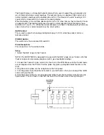
Страница 1: ...and has a LCD display with a fast responding analog bargraph and a digital readout An inductive probe is used to trace current flow in the PCB HOW TO USE THE SHORTRACK This section explains how to use your instrument Topics included are Description of physical features and their operation Setup procedure Application examples Features This section describes the features of your instrument Refer to ...

Страница 2: ...digital displays to 100 while the probe monitors a reference current POWER Switch This switch turns the instrument ON and OFF Probe Receptacle This connector is for the current probe Setup 1 Select the LOW range on the Tracker NOTE The SHORTRACK is designed to be used with the LOW range of any Tracker All other Tracker ranges do not provide enough current to give meaningful readings 2 Connect the ...

Страница 3: ...ce the reading will drop to zero when you pass the short or the current branches off into another trace If there is no other physical branch where the reading goes to zero inspect that location for the fault that is causing the short Applications Now that you have a basic idea of how to use the SHORTRACK we will provide several examples covering various types of low impedance faults Hard Shorts le...

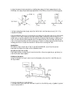
Страница 4: ...f the PCB Cutting the area between the two traces can remove the short and restore the proper signature that should exist when the Tracker leads are connected to the two traces Backplane Example A common problem in a manufacturing environment is a solder bridge between adjacent pins of a device In this example you have detected a short between two adjacent traces on the backplane PCB shown in the ...

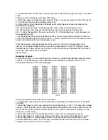
Страница 5: ...t A 2 Align the probe and adjust GAIN for a reading of 100 3 Probe point B The reading will be 100 so all the current at point A is still flowing at point B 4 Probe point C The display will drop to zero because point C is past the fault U2 is the suspect IC and you can verify that current is flowing through it by putting the probe on top of U2 This will show a fairly strong reading 40 60 whereas t...

Страница 6: ... not pick the best location for connecting the Tracker leads to the PCB the first time moving the Tracker leads around can be a normal part of short location MAINTENANCE Repairs or servicing not covered in this manual should only be performed by qualified service personnel as described in the HUNTRON SHORTRACK Model 90 Service Manual contact Huntron for availability General Maintenance To clean th...

Страница 7: ...lease include a description of the malfunction An instrument under warranty will be promptly repaired or replaced at Huntron s option and returned at no charge See the front of this manual for warranty terms If the warranty has lapsed the instrument will be repaired and returned for a service fee Contact Huntron for prices SPECIFICATIONS Signal Source LOW range of a Huntron Tracker open circuit vo...

Отзывы: