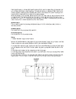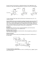
6. Align the probe for best sensitivity by orienting the wide part of the tip perpendicular to the
PCB trace. Also keep the probe body perpendicular to the PCB as shown in the following figure.
7. While holding the probe steady, adjust the GAIN control until the display reads 100%. This
completes the setup.
The SHORTRACK will now give an approximate indication of the relative amount of current (with
respect to 100%) that is flowing in any trace that the probe is placed on. When looking for an
actual fault, you use the probe to follow the current by locating a trace that gives a reading of 90-
100%. As you move the probe along the trace, the reading will drop to zero when you pass the
short or the current branches off into another trace. If there is no other physical branch where the
reading goes to zero, inspect that location for the fault that is causing the short.
Applications
Now that you have a basic idea of how to use the SHORTRACK, we will provide several
examples covering various types of low impedance faults.
Hard Shorts (less than 1ohm)
The Tracker shows a vertical line for hard shorts which is the same signature you get when you
short the Tracker leads together.
PCB Defect Example:
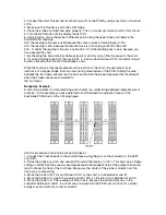
Using the Tracker, you have found a hard short between points A and N on the PCB shown in
the figure below.
Follow this procedure to locate the fault:
1. Connect one of the Tracker test terminals to point A on the PCB by using a "grabber" type test
clip on one lead of R12.


