background image

10

JIN04MKIIC_V1 10/01/17

GAS SUPPLY CONNECTIONS

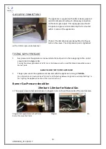
The appliance is supplied with an 8mm Bundy pipe and
an 8mm compression elbow to allow easy connection
to the mains gas supply.  This supply gas pipe should
incorporate a gas service isolation tap that is situated
within 1 metre of the application.

Photo 3: The 8mm Bundy pipe being fitted to the gas
inlet on the valve.  The compression joint is tightened

with a 14mm open-ended spanner.

TESTING SUPPLY PRESSURE

1.

Gas pressure at the appliance is measured via the test point on the tube going to the control

valve (circled in diagram 3b).

Turning the screw approximately half a turn anti-clockwise with a small flat-bladed screwdriver opens

the test point.

ALWAYS CLOSE TEST POINTS AFTER USE!

2.

The gas pressure at the appliance is measured with the appliance running at

full rate

.

(For information on how to achieve ‘full rate’ read ‘Adjusting Between High and Low Output Settings’ in

the ‘Lighting the Appliance’ section of the User Instructions).

Burner Gas Pressure should be:

19mbar ± 1.0mbar for Natural Gas

3. The supply pressure test point (shown in diagram 3a) is on the left-hand side of the control valve.

Diagram 3a: Supply Pressure Test Point.

Diagram

3b:

Burner Pressure Test Point.

Содержание HUNTER HAWK 4 MKII

Страница 1: ...ase leave this instruction booklet with the user after the installation is complete Leave the system ready for operation and instruct the user in the correct use of the appliance and operation of its...

Страница 2: ...RESSURE 10 INSTALLATION OF THE FIRE BED INTO THE STOVE 11 FITTING THE CANOPY OPTIONAL 14 SPILLAGE MONITORING SYSTEM 14 SERVICING INSTRUCTIONS 16 SPARES 17 Please read these instructions carefully This...

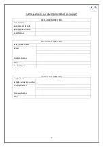
Страница 3: ...ler Retailer Name Address Telephone Number Email Date Purchased APPLIANCE INFORMATION Date Installed Appliance Stock Code Appliance Description Serial Number INSTALLER INFORMATION Installer Name Gas S...

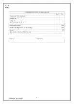
Страница 4: ...IONING CHECK Complete Sign Pass Fail Flue is correct for the appliance Flue flow test Spillage test Gas soundness let by test Standing gas pressure mbar Appliance working pressure on High Setting mbar...

Страница 5: ...GAS Nominal Gas Pressure 20mbar Supply Gas Type Category G20 I2H Injector Type Marking 59 Heat Input Gross Full Low 4 7kW 3 5kW Gas Flow Rate m3 h Full 0 447 NOx Class 4 Efficiency Class 2 Countries o...

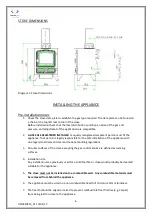
Страница 6: ...legally responsible for the safe installation of the appliance with due regard to all relevant local and national building regulations 3 All outer surfaces of the stove excepting the gas control knob...

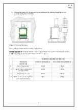
Страница 7: ...e clearance must be given between the appliance and the walls so that a satisfactory spillage test can be performed as detailed on page 17 MINIMUM CLEARANCE DISTANCES TO DIMENSION DESCRIPTION COMBUSTI...

Страница 8: ...ney block It is suggested to run flue pipe at least 615mm vertically from the unit before there are any changes in direction of the flue system Wherever possible horizontal runs of the flue system sho...

Страница 9: ...to the burner tray first make sure that the stove is switched off and is cold Firstly remove the door handle by turning anticlockwise Keep turning until the handle is completely removed as shown in p...

Страница 10: ...test point on the tube going to the control valve circled in diagram 3b Turning the screw approximately half a turn anti clockwise with a small flat bladed screwdriver opens the test point ALWAYS CLOS...

Страница 11: ...ER STOVES LTD ACCEPTS NO RESPONSIBILITY FOR ANY INJURY HOWEVER CAUSED WHILST HANDLING HOT COALS LOGS OR CERAMICS FIRE BED ARRANGEMENT This appliance can be fitted with log effect ceramics The fire bed...

Страница 12: ...left hand fork should then rest on the edge of the matrix and the side of the stove As shown in photo 7 Photo 7 Installing Log B 4 Log C sits in a groove to the right of Log B behind the third flame...

Страница 13: ...matrix the top resting on log C to the left of it photo 10 The log picture is now complete The stove should be lit and the flame picture checked with the door sealed shut Any adjustments to the flame...

Страница 14: ...se all doors and windows in the room containing the fire before the test is carried out Complete the Ceramic Coal or Log picture close the door and replace the handle 1 Ensure that the fire is burning...

Страница 15: ...by lack of flue pull or flue blockage The spillage system MUST NOT be adjusted modified or put out of action by the installer The spillage system MUST NOT be removed or bridged out for any reason If...

Страница 16: ...n away any lint or light carbon soot deposits out of the gas ports on the burner top plate 4 Replace the ceramic matrix and loose coals logs as per the fire bed arrangement instructions Page 11 using...

Страница 17: ...PHKDRSK DOOR ROPE KIT STANDARD DOOR SCPHKRSK GAS BURNER FULL ASSEMBLY 4kW NATURAL GAS MANUAL CONTROL GYB04NYM OXIPILOT 6kW 4kW GAS BURNER CFB06102 GAS VALVE MANUAL CFB06100 KNOB MANUAL GAS VALVE 6kW 4...

Отзывы: