


Hunter e36 • AC Electric Systems
8.4
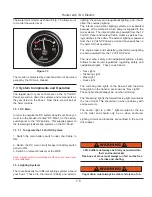
Figure 8.5
8.1.2.1 To Disconnect Shore Power
On the boat: Turn off all breakers
A. Turn off equipment breakers.
B. Turn off shore power breaker.
C. Turn off shore Inlet Breaker.
D. On the dock: Turn off the dock breaker
E. Disconnect the dock side power cord.
F. On the boat:
Disconnect the power cord from the
boat.
8.1.3 Shore Power Cable
The shore power cable set is intended for use outdoors.
To prolong the life of the set, store indoors when not in
use. The metallic parts of your cable set are made to
resist corrosion. In a salt-water environment, periodically
wiping the exposed parts with fresh water, drying and
spraying with a moisture repellent can increase life of the
product. A soiled cable can be cleaned with a grease cut-
ting household detergent. A periodic application of vinyl
protector to both ends will help to maintain cables original
appearance.
Incase of salt water immersion, rinse plug end and/or
connector end thoroughly in freah water, shake or blow
out excess water and allow to dry. Spray with moisture
repellent before re-use.
WARNING
!
!
DO NOT allow the dockside power cord to come in
contact with the water. Never operate any power
tool or other electrical equipment while you or the
devices are in contact with the water, as this may
cause electrocution resulting in shock or death.
8.1.4 Isolation Transformer (Option)
Beyond the shore power connection and the shore
power breaker, your AC power will be routed through the
Isolation Transformer. See the Mechanical Arrangement
Illustration for the location of the ISO Transformer.
The ISO Transformer is a standard “dry” type 3.6 KVA
transformer that basically isolates your boat from the
shore power. It is a valuable safety feature aboard your
boat.
8.1.5 AC Distribution Panel
The distribution panels for both AC and DC power are
located behind the nav station seat.
8.1.6 Generator (Option)
The standard generator on your boat provides 120VAC
60 HZ for operating devices and equipment controlled
through the AC Distribution Panel. The generator is also
controlled from the AC Distribution Panel.
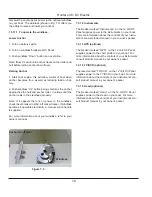
8.1.6.1 Connecting Generator Power
Before connecting generator power to the AC system:
A. Turn off all AC devices and equipment.
B. Disconnect shore power if connected. Set AC Main
circuit breakers to OFF.
C. Start generator. (See generator startup instructions
following)
D. Move slide bar up to lock out shore power. Set genera-
tor breaker ON.
E. Switch on only the circuits you will be using.
E
F
Содержание e36
Страница 1: ...V2 062012 Operator s Manual e 36 ...
Страница 2: ......
Страница 9: ...V2 062012 Introduction e 36 Chapter 1 ...
Страница 14: ...Hunter e36 Introduction 1 6 Notes ...
Страница 15: ...Documents Forms e 36 Chapter 2 and V2 062012 ...
Страница 26: ...Hunter e36 Documents and Forms Maintenance Log Date Maintenance Performed Hourmeter 2 12 ...
Страница 27: ...Hunter e36 Documents and Forms 2 13 Date Maintenance Performed Hourmeter Maintenance Log ...
Страница 30: ...Hunter e36 Documents and Forms Power Squadron recommendations for maintenance and safe boating 2 16 ...
Страница 31: ...Hunter e36 Documents and Forms 2 17 Local sailing club or marina s recommendations for maintenance and up keep ...
Страница 33: ...Hunter e36 Documents and Forms 2 19 Spare Parts List ...
Страница 34: ...Hunter e36 Documents and Forms Dates of practice drills and onboard safety inspections 2 20 ...
Страница 35: ...Hunter e36 Documents and Forms 2 21 My personal preferences for maintenance items safety gear ...
Страница 36: ...Hunter e36 Documents and Forms Notes 2 22 ...
Страница 37: ...V2 062012 Limited Warranty e 36 Chapter 3 ...
Страница 38: ...This Page Intentionally Left Blank Hunter Limited Warranty 3 2 ...
Страница 47: ...Boating Safety e 36 Chapter 4 V2 062012 ...
Страница 65: ...Deck Hardware Hunter e36 Boating Safety 4 19 ...
Страница 67: ...Hunter e36 Boating Safety 4 21 Notes ...
Страница 68: ...Hunter e36 Boating Safety 4 22 Notes ...
Страница 69: ...V2 062012 Fuel Systems e 36 Chapter 5 ...
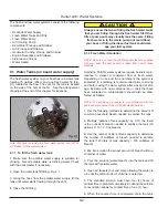
Страница 75: ...Fig 5 7 A Quick Fuel Filter Reference Hunter e36 Fuel Systems 5 7 ...
Страница 82: ...Notes Hunter e36 Fuel Systems 5 14 ...
Страница 83: ...V2 062012 Underwater Gear e 36 Chapter 6 ...
Страница 92: ...Hunter e36 Underwater Gear 6 10 Notes ...
Страница 93: ...V2 062012 DC Electric Systems e 36 Chapter 7 ...
Страница 103: ...Hunter e36 DC Electric 7 11 7 8 BASIC DC POWER SUPPLY SYSTEM DIAGRAM ...
Страница 104: ...Hunter e36 DC Electric 7 12 Notes ...
Страница 106: ...Hunter e36 DC Electric 7 14 Notes ...
Страница 107: ...V2 062012 AC Electric Systems e 36 Chapter 8 ...
Страница 115: ...Hunter e36 AC Electric Systems 8 9 7 8 AC DC Electric Power Supply Diagram ...
Страница 116: ...Hunter e36 AC Electric Systems 8 10 This Page Intentionally Left Blank ...
Страница 117: ...Hunter e36 AC Electric Systems 8 11 Notes ...
Страница 118: ...Hunter e36 AC Electric Systems 8 12 Notes ...
Страница 119: ...V2 062012 Water Systems e 36 Chapter 9 ...
Страница 126: ...Hunter e36 Water Systems 9 8 This Page Intentionally Left Blank ...
Страница 128: ...Hunter e36 Water Systems 9 10 This Page Intentionally Left Blank ...
Страница 129: ...Hunter e36 Water Systems 9 11 Notes ...
Страница 130: ...Hunter e36 Water Systems 9 12 Notes ...
Страница 131: ...V2 062012 Waste Systems e 36 Chapter 10 ...
Страница 137: ...Hunter e36 Waste and Sanitation Systems 10 7 ...
Страница 140: ...This Page Intentionally Left Blank Hunter e36 Waste and Sanitation Systems 10 10 ...
Страница 141: ...Sump Pump Layout Grey Water Hunter e36 Waste and Sanitation Systems 10 11 ...
Страница 142: ...This Page Intentionally Left Blank Hunter e36 Waste and Sanitation Systems 10 12 ...
Страница 144: ...Hunter e36 Waste and Sanitation Systems 10 14 Notes ...
Страница 145: ...V2 062012 Engines Transmissions e 36 Chapter 11 and ...
Страница 154: ...Hunter e36 Engines and Transmissions 11 10 This Page Intentional Left Blank ...
Страница 155: ...V2 062012 Sails Rigging e 36 Chapter 12 and ...
Страница 161: ...Hunter e36 Sails and Rigging 12 7 I 44 10 13 66m J 13 2 4 01m P 44 11 13 68m E STD 15 4 572m E FURL 16 4 876m P I E J ...
Страница 162: ...Hunter e36 Sails and Rigging 12 8 Standing Rigging Details Standard ...
Страница 163: ...Hunter e36 Sails and Rigging 12 9 Standing Rigging Details Furling ...
Страница 164: ...Hunter e36 Sails and Rigging 12 10 Mast Upper Spreader Tip Details H A B C D E F G ...
Страница 165: ...Hunter e36 Sails and Rigging 12 11 C A B D E F G H J K I Mast Lower Spreader Tip Details ...
Страница 166: ...Hunter e36 Sails and Rigging 12 12 Standing Rigging Details ...
Страница 170: ...Hunter e36 Sails and Rigging 12 16 Typical Boom Reefing Layout ...
Страница 171: ...Hunter e36 Sails and Rigging 12 17 Rope Vang Details Standard Vang Details ...
Страница 172: ...Hunter e36 Sails and Rigging 12 18 Rigid Vang Details Optional Vang Details ...
Страница 175: ...Hunter e36 Sails and Rigging 12 21 JIB LINE TIES OFF ON CLEAT Jib Furling Line Layout ...
Страница 176: ...Hunter e36 Sails and Rigging 12 22 Bridle Configuration ...
Страница 179: ...Hunter e36 Sails and Rigging 12 25 Optional Spinnaker Layout ...
Страница 180: ...Hunter e36 Sails and Rigging 12 26 Notes ...
Страница 181: ...V2 062012 Getting Underway e 36 Chapter 13 ...
Страница 188: ...Hunter e36 Getting Underway 13 8 Notes ...
Страница 189: ...V2 062012 Maintenance e 36 Chapter 14 ...
Страница 202: ...Notes Hunter e36 Maintenance 14 14 ...
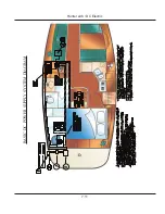
Страница 203: ...Exterior Lifting Points Hunter e36 Maintenance 14 15 ...
Страница 204: ...Hunter e36 Maintenance 14 16 This Page Intentionally Left Blank ...
Страница 205: ...V2 062012 Glossary e 36 Chapter 15 ...