Hunter 50
CC
• DC Electric
7.4
The battery switch panel houses the breakers for some
of the main components in your DC system. The breaker
controls are marked at the switch panel, and control sys-
tems or components on your boat that require a connec-
tion that remains energized even through the Main Panel
may be de-energized.
The breakers and switches are described in greater detail
in the “Breakers and Switches” section of this chapter.
7.1.3 Battery Charging System
Refer to the power supply locator drawing (Fig. 7.1) at
the beginning of this section for the location of the battery
charger. The charger is protected by a fuse on the posi-
tive and ground side at the charger.
To operate the charger, ensure that it is operating:
Connect the shore power cord to the shore power
inlet on the stern of the boat on the stbd. side. Then to
the dockside supply.
Turn on the AC Main breaker, located in the aft cabin.
Turn on the Battery Charger switch on the control
panel.
7.1.5 Breakers, Switches, and Fuses
All electrical systems aboard your boat are provided with
over-current protection in the form of breakers or fuses.
Examples of breakers are the system or component con-
trols at the Main Distribution Panel, or MDP, or in the bat-
tery selector switch panel. Systems that would normally
1.
2.
3.
require you to energize them for use are provided with
switches.
The breaker and switch panels are detailed fur-
ther in the end of this section under “Legends.”
7.1.7 Generator (Option)
Although, technically, the generator is part of the AC
System, because it supplies AC power, the starting of
the generator requires DC power. The generator starting
receives power from the start battery bank.
The generator supplies 120/240, volt 60 hz AC power for
operating devices and equipment controlled through the
AC control panel (Main Distribution Panel, MDP).
When the generator indicating light is on and the genera-
tor breakers are on, AC power is supplied to AC control
panel devices and equipment.
Refer to the “Operation and Procedures” part of the AC
Electric section for information on starting the generator.
You can find or locate the generator and all the respective
components using the Generator System Drawing at the
end of this chapter.
7.1.8 Main Control Panel (DC Side)
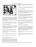
You can view the parts of the DC side of the main control
panel here (Fig. 7.3). Notice the battery selector switch at
the top left, when switched on the respective voltage of
the battery is shown on the right by the digital volt meter.
Indicator lights are built into most switches and alert you
that the selected system is powered.
The distribution panel is outlined in the legends section
of this chapter.
Refer to the “Operations” section of this chapter to view
instructions on how to energize the separate systems on
your boat.
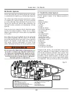
Fig.7.2
Содержание 50CC
Страница 1: ...Operator s Operator s Manual Manual Hunter 5 Hunter 50 0cc cc ...
Страница 2: ......
Страница 9: ...Introduction Introduction Hunter 50cc Hunter 50cc Chapter 1 Chapter 1 ...
Страница 14: ...Hunter 50cc Introduction 1 6 Notes ...
Страница 15: ...Documents Documents Forms Forms Hunter 50cc Hunter 50cc Chapter 2 Chapter 2 ...
Страница 26: ...Hunter 50CC Documents and Forms Maintenance Log Date Maintenance Performed Hourmeter 2 12 ...
Страница 27: ...Hunter 50CC Documents and Forms 2 13 Date Maintenance Performed Hourmeter Maintenance Log ...
Страница 30: ...Hunter 50CC Documents and Forms Power Squadron recommendations for maintenance and safe boating 2 16 ...
Страница 33: ...Hunter 50CC Documents and Forms 2 19 Spare Parts List ...
Страница 34: ...Hunter 50CC Documents and Forms Dates of practice drills and onboard safety inspections 2 20 ...
Страница 35: ...Hunter 50CC Documents and Forms 2 21 My personal preferences for maintenance items safety gear ...
Страница 36: ...Hunter 50CC Documents and Forms Notes 2 22 ...
Страница 37: ...DC 071609 Limited Limited Warranty Warranty Chapter 3 Chapter 3 ...
Страница 38: ...This Page Intentionally Left Blank Hunter Limited Warranty 3 2 ...
Страница 47: ...Boating Safety Boating Safety Hunter 50cc Hunter 50cc Chapter 4 Chapter 4 ...
Страница 66: ...Hunter 50CC Boating Safety 4 20 Notes ...
Страница 67: ...Fuel Systems Fuel Systems Hunter 50cc Hunter 50cc Chapter 5 Chapter 5 ...
Страница 73: ...Fig 5 7 A Quick Fuel Filter Reference Hunter 50CC Fuel Systems 5 7 ...
Страница 81: ...Underwater Underwater Gear Gear Hunter 50cc Hunter 50cc Chapter 6 Chapter 6 ...
Страница 92: ...Hunter 50CC Underwater Gear 6 12 Notes ...
Страница 93: ...DC Electrical DC Electrical Systems Systems Hunter 50cc Hunter 50cc Chapter 7 Chapter 7 ...
Страница 104: ...NAV LIGHT BREAKER DECK LIGHT BEAKER D Hunter 50CC DC Electric 7 12 ...
Страница 105: ...AC Electric AC Electric Systems Systems Hunter 50cc Hunter 50cc Chapter 8 Chapter 8 ...
Страница 114: ...Hunter 50cc AC Electric Systems 8 10 Notes ...
Страница 115: ...Water Systems Water Systems Hunter 50cc Hunter 50cc Chapter 9 Chapter 9 ...
Страница 127: ...Waste Waste Systems Systems Hunter 50cc Hunter 50cc Chapter 10 Chapter 10 ...
Страница 140: ...Notes Hunter 50CC Waste and Sanitation Systems 10 14 ...
Страница 141: ...Engine Engine and and Transmissions Transmissions Hunter 50cc Hunter 50cc Chapter 11 Chapter 11 ...
Страница 150: ...Hunter 50CC Engines and Transmissions 11 10 Notes ...
Страница 151: ...Sails Sails and and Riggings Riggings Hunter 50cc Hunter 50cc Chapter 12 Chapter 12 ...
Страница 159: ...12 9 C A B D E F G H J K I H A B C D E F G UPPER SPREADER TIP LOWER SPREADER TIP 50cc STANDING RIGGING DETAILS ...
Страница 164: ...12 14 CAMCLEAT 1 2 5 4 11 3 2 12 7 8 9 10 6 50cc DUAL END MAINSHEET PURCHASE ARRANGEMENT ...
Страница 175: ...Hunter 50cc Hunter 50cc Getting Getting Underway Underway Chapter 13 Chapter 13 ...
Страница 182: ...Hunter 50CC Getting Underway 13 8 Notes ...
Страница 183: ...Maintenance Chapter 14 Chapter 14 Hunter 50cc Hunter 50cc ...
Страница 195: ...Glossary Glossary Chapter 15 Chapter 15 Hunter 50cc Hunter 50cc ...


