Hunter 50cc • AC Electric Systems
8.5
8.2.2 Water Heater
CAUTION
!
!
Be certain the water heater is full of water and does
not contain air. If the water heater is not full of wa-
ter, damage to the heating elements may result when
electrical power is turned on to the unit.
The water heater use and function is described in the
Water Systems Section. Here we will detail the electrical
side of the heater.
The water heater is powered by the MDP on the
Navigation Station. It is much the same as an electric
water heater in your home, Consult the manufacturer’s
documentation for any internal information about the
water heater.
When the Water Heater is operating from the Heat
Exchanger, water temperature in the tank will approach
the temperature of the engine coolant.
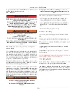
The Temperature Control Valve (TCV) regulates the flow
of coolant through the Heat
Exchanger by sensing the output temperature of the
water in the tank
Hotter
3
/
32
" Hex Wrench
Turn
Colder
Unscrew, lift
cap to adjust
WARNING!!
Water temperatures
in excess 110ºF
(43ºC) are dangerous
and may cause
scalding, severe
injury or death!
See the equipment’s
owners’ manual for
more details
8.2.2.1 Water Heater Maintenance
1. Disconnect AC Power prior to draining the water sys-
tem.
2. Flush Tank periodically.
3. If the temperature in the tank environment is going
to drop below 32 deg F (0 C), drain the tank to prevent
freezing and possible damage. (See water heater own-
er’s manual for for detail)
8.2.3 Microwave and Coffee Maker
The microwave is powered with the 120 volt (230 over-
seas) power through the breaker marked “Microwave.”
There is a 120 volt (220 overseas) receptacle behind the
microwave that it is plugged into. This outlet is not part of
the GFI circuit. It is protected by the breaker on the MDP.
Refer to microwave user’s manual, coffee maker user’s
manual for more detail operating instruction information.
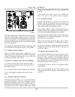
Fig. 8.3.5
shows the basic description of the microwave
1. Door Safety Lock System
2. Oven
Window
3. Oven
Air
Vent
4. Shaft
5. Roller
Ring
6. Glass
Tray
7. Control
Panel
8. Grill
Heater
9. Baking
plate
10. Baking Rack
8.2.6 Air Conditioning
The Air Conditioning system is 240 volt (230 overseas)
AC powered and powered from the AC sub panel at the
lower helm.
The cooling water pump is controlled by a relay at the
compressor and is energized when the Air Conditioning
Compressor comes on.
You can consult the Arrangement Illustration at the end of
this section for location information, or see the Mechanical
Arrangement in the Boating Safety Section. The Water
Systems will show you the Pick-up and Strainer for this
Содержание 50CC
Страница 1: ...Operator s Operator s Manual Manual Hunter 5 Hunter 50 0cc cc ...
Страница 2: ......
Страница 9: ...Introduction Introduction Hunter 50cc Hunter 50cc Chapter 1 Chapter 1 ...
Страница 14: ...Hunter 50cc Introduction 1 6 Notes ...
Страница 15: ...Documents Documents Forms Forms Hunter 50cc Hunter 50cc Chapter 2 Chapter 2 ...
Страница 26: ...Hunter 50CC Documents and Forms Maintenance Log Date Maintenance Performed Hourmeter 2 12 ...
Страница 27: ...Hunter 50CC Documents and Forms 2 13 Date Maintenance Performed Hourmeter Maintenance Log ...
Страница 30: ...Hunter 50CC Documents and Forms Power Squadron recommendations for maintenance and safe boating 2 16 ...
Страница 33: ...Hunter 50CC Documents and Forms 2 19 Spare Parts List ...
Страница 34: ...Hunter 50CC Documents and Forms Dates of practice drills and onboard safety inspections 2 20 ...
Страница 35: ...Hunter 50CC Documents and Forms 2 21 My personal preferences for maintenance items safety gear ...
Страница 36: ...Hunter 50CC Documents and Forms Notes 2 22 ...
Страница 37: ...DC 071609 Limited Limited Warranty Warranty Chapter 3 Chapter 3 ...
Страница 38: ...This Page Intentionally Left Blank Hunter Limited Warranty 3 2 ...
Страница 47: ...Boating Safety Boating Safety Hunter 50cc Hunter 50cc Chapter 4 Chapter 4 ...
Страница 66: ...Hunter 50CC Boating Safety 4 20 Notes ...
Страница 67: ...Fuel Systems Fuel Systems Hunter 50cc Hunter 50cc Chapter 5 Chapter 5 ...
Страница 73: ...Fig 5 7 A Quick Fuel Filter Reference Hunter 50CC Fuel Systems 5 7 ...
Страница 81: ...Underwater Underwater Gear Gear Hunter 50cc Hunter 50cc Chapter 6 Chapter 6 ...
Страница 92: ...Hunter 50CC Underwater Gear 6 12 Notes ...
Страница 93: ...DC Electrical DC Electrical Systems Systems Hunter 50cc Hunter 50cc Chapter 7 Chapter 7 ...
Страница 104: ...NAV LIGHT BREAKER DECK LIGHT BEAKER D Hunter 50CC DC Electric 7 12 ...
Страница 105: ...AC Electric AC Electric Systems Systems Hunter 50cc Hunter 50cc Chapter 8 Chapter 8 ...
Страница 114: ...Hunter 50cc AC Electric Systems 8 10 Notes ...
Страница 115: ...Water Systems Water Systems Hunter 50cc Hunter 50cc Chapter 9 Chapter 9 ...
Страница 127: ...Waste Waste Systems Systems Hunter 50cc Hunter 50cc Chapter 10 Chapter 10 ...
Страница 140: ...Notes Hunter 50CC Waste and Sanitation Systems 10 14 ...
Страница 141: ...Engine Engine and and Transmissions Transmissions Hunter 50cc Hunter 50cc Chapter 11 Chapter 11 ...
Страница 150: ...Hunter 50CC Engines and Transmissions 11 10 Notes ...
Страница 151: ...Sails Sails and and Riggings Riggings Hunter 50cc Hunter 50cc Chapter 12 Chapter 12 ...
Страница 159: ...12 9 C A B D E F G H J K I H A B C D E F G UPPER SPREADER TIP LOWER SPREADER TIP 50cc STANDING RIGGING DETAILS ...
Страница 164: ...12 14 CAMCLEAT 1 2 5 4 11 3 2 12 7 8 9 10 6 50cc DUAL END MAINSHEET PURCHASE ARRANGEMENT ...
Страница 175: ...Hunter 50cc Hunter 50cc Getting Getting Underway Underway Chapter 13 Chapter 13 ...
Страница 182: ...Hunter 50CC Getting Underway 13 8 Notes ...
Страница 183: ...Maintenance Chapter 14 Chapter 14 Hunter 50cc Hunter 50cc ...
Страница 195: ...Glossary Glossary Chapter 15 Chapter 15 Hunter 50cc Hunter 50cc ...


