Hunt Electronic HDR503 Series Скачать руководство пользователя страница 30


29


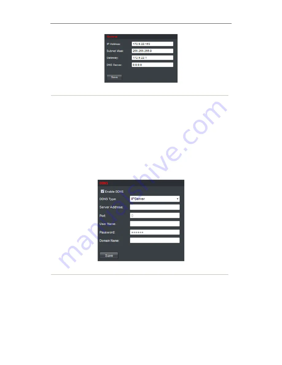
Figure 4.27 Configure Basic Network Settings 


2.


Set the network parameters, including the IP Address, Subnet Mask, Gateway and DNS Server. 

3.


Click 

Save

 to save the settings. 


4.2.4 Configuring DDNS Settings  

Purpose: 

If your device is set to use PPPoE as its default network connection, you may set Dynamic DNS (DDNS) to be 

used for network access.  

Prior registration with your DDNS Provider is required before configuring the system to use DDNS. 

Steps: 

1.


Click 

Configuration 

Network Settings 

DDNS

 to enter the DDNS Settings interface: 


Figure 4.28 Configure DDNS Settings


2.


Check the 

Enable


DDNS

 checkbox to enable this feature. 

3.


Select 

DDNS Type

. Four different DDNS types are selectable: IPServer, DynDNS, PeanutHull and 

HiDDNS. 


DynDNS:  

(1)


Enter 

Server Address

 for DynDNS (e.g., members.dyndns.org). 

(2)


Enter the 

User Name 

and 

Password 

registered in the DynDNS website.  

(3)


In the 

Device Domain Name

 text field, enter the domain obtained from the DynDNS website. 

(4)


Click 

Save

 to save the settings.  

Содержание HDR503 Series

Страница 1: ...HD Video Audio Decoder HDR503 Series Decoder User Manual V2 3 0 ...

Страница 2: ...luding interference that may cause undesired operation EU Conformity Statement This product and if applicable the supplied accessories too are marked with CE and comply therefore with the applicable harmonized European standards listed under the Low Voltage Directive 2006 95 EC the EMC Directive 2004 108 EC the RoHS Directive 2011 65 EU 2012 19 EU WEEE directive Products marked with this symbol ca...

Страница 3: ...er work in the allowed range of temperature and humidity Please keep the device horizontal and avoid the installation under severe vibration environment The dust board will cause a short circuit after damping Please remove dust regularly for the board connector chassis fan and other parts of the device with brush Improper use or replacement of the battery may result in hazard of explosion Replace ...

Страница 4: ...16 4 1 3 Configuring Cycle Decoding 19 4 1 4 Configuring Video Wall Display 20 4 1 5 Enabling Disabling the Decoding Channel 22 4 1 6 Configuring Picture Overlay 22 4 1 7 Checking the Connection Status 23 4 1 8 Checking the Decoding Channel Status 24 4 1 9 Checking the Display Channel Status 24 4 1 10 Configuring Transparent Channel 25 4 2 Decoder Configuration 27 4 2 1 Checking Device Information...

Страница 5: ... Default Settings for the Decoder 40 CHAPTER 5 Decoder Configuration and Operation by Client Software 42 5 1 Adding an Encoder 43 5 2 Adding a Decoder 47 5 3 Setting TV Wall Layout 49 5 4 Decoding Operation 51 5 5 Configuring Remote Setting for the Decoder 53 CHAPTER 6 Appendix 54 Appendix A Specifications 55 Appendix B FAQ 56 Appendix C List of Third party IP Cameras Access 57 ...

Страница 6: ...5 CHAPTER 1 Introduction ...

Страница 7: ...hod High definition video output via VGA HDMI connector and standard definition video output via BNC connector Window jointing for video wall display Decoding Capacity Refer to the following table for the decoding capacity and display modes of different models Resolution Model Resolution Video Output Window division Mode Multi display Mode 5MP 1080P 720P 4CIF HDR503 1 2 channels 4 channels 8 chann...

Страница 8: ...online devices in local network area Automatically get IP address by DHCP protocol Remote upgrading and maintenance can be done via web browser or client software User Administration A maximum of 32 user accounts can be created by the system including 1 administrator and 31 normal users The user name of the administrator is admin which cannot be modified and the password is allowable to be modifie...

Страница 9: ...8 CHAPTER 2 Panels and Connections ...

Страница 10: ... output of decoded video 3 VIDEO OUT DB15 connector for video output connecting to video output device e g monitor with the DB15 to BNC adapter 4 LINE IN OUT Two way audio input output 3 5mm connector 5 AUDIO OUT DB15 connector for audio out connecting to audio output device with the DB15 to BNC adapter 6 LAN 10 100 1000 Mbps Ethernet interface 7 RS 485 Serial Interface Connect to RS 485 devices e...

Страница 11: ...10 CHAPTER 3 Initial Network Parameters Configuration ...

Страница 12: ...r the default user name of HDR503 series is admin and password is 12345 And the default IP address is 192 0 0 64 3 1 Searching Active Devices Online z Search online devices automatically Click to run the SADP software and it will automatically search the online devices every 15 seconds from the subnet where your computer locates It displays the total number and information of the searched devices ...

Страница 13: ...l on the right side or click to show the network parameter panel 3 2 Modifying Network Parameters Steps 1 Select the device to be modified in the device list and the network parameters of the device will be displayed in the Modify Network Parameters panel on the right side 2 Edit the modifiable network parameters e g IP address port number and gateway 3 Enter the password of the admin account of t...

Страница 14: ...13 CHAPTER 4 Decoder Configuration and Operation by Web Browser ...

Страница 15: ...clude IE7 and IE8 chrome safari and firefox4 Open the Web browser and input the IP address of Decoder e g http 192 168 0 0 to enter the login page Figure 4 1 Login Interface Enter the user name and password of the device in the dialog box and then click Login to log into the system By default the user name for login is admin and the password is 12345 The main interface of the control panel of the ...

Страница 16: ... HDMI outputs Steps 1 Click Decode Operation Decode Mode Display Control to enter the display control interface Figure 4 3 Display Configure 2 In the display control interface you can configure the Display Channel Video Format BNC BNC Output Scaling BNC Output Resolution VGA HDMI and Display Mode Figure 4 4 Configure Display Parameters 3 Select the window division display mode The HDR503 series su...

Страница 17: ...n the Sub window Configuration field will be displayed in Task 2 Restore the Sub window Steps 1 Click the button again and the following prompt will pop up Figure 4 7 Restore the Sub window 2 Click OK to exit the full screen mode of the selected sub window and the Window Enlarged in the Sub window Configuration field will be displayed in 4 1 2 Configuring Dynamic Decoding After you have configured...

Страница 18: ...tream ID Normal Get the stream from the encoding device by IP address Channel zero Get the stream from encoding device DVR by channel zero Stream ID Get the stream from the device transcoder which supports access by stream ID yRemote Host Channel No Enter the channel No of the encoding device for decoding yUser Name Password Enter the user name and password used for login to the encoding device yT...

Страница 19: ... x Input the version of the stream media server Example rtsp 172 9 22 41 554 hikvision 172 9 22 215 8000 0 0 username admin password 12345 linkmode tcp sm version 4 Notes 1 The length of URL should be less than 240 bytes 2 The URL mode can only be activated when using with the SMS 4 0 or above version of iVMS 4200 client software Task 3 Set Encoding Device by DDNS Mode Figure 4 10 Set Encoding Dev...

Страница 20: ...ub stream is supported for decoding when the encoding device supports dual stream 4 Click Start Decoding to start decoding and the decoding status can be viewed in the Connection Status or the Decoding Channel status interface And you can view the image from the remote encoding device that is decoded and displayed on the screen 4 1 3 Configuring Cycle Decoding Purpose Comparing with the dynamic de...

Страница 21: ... edit other input streams for cycle decoding You can also click Delete to remove the configured input stream from the list Note Up to 64 input streams can be configured for each cycle decoding channel Figure 4 13 Configure Input Streams for Decoding 7 Click Save to save the configuration of input streams for the cycle decoding Example Configuration Decoding Channel Channel 1 Cycle Time 10 seconds ...

Страница 22: ...ll 5 Set the Output Resolution Note You can select the NOT_AVAILABLE option in the Output Resolution to clear the current video wall configuration 6 In the Video Output Configuration area select the Display Channel for each screen 7 Click Save to save the settings Notes 1 The BNC video output does not support large screen display currently 2 It is recommended to configure the display channels with...

Страница 23: ...ce Figure 4 16 Configure Channel On Off 2 Select a decode channel in the drop down list in the Decode Channel field 3 Set the decoding channel to On or Off 4 Click Save to save the settings 4 1 6 Configuring Picture Overlay Purpose The Picture Overlay function can overlay a picture on the screen for the selected decode channel and the position of the picture overlaid on the screen can also be set ...

Страница 24: ...e must be in 24 bit BMP format and its width and height must be 32X pixel with up to 128 128 resolution and 24 bits depth 5 You can check the checkbox of Flash to set the display style of the picture 6 Set the picture to show or hide 7 Click Save to save the settings 4 1 7 Checking the Connection Status Purpose The connection status shows the status of the decoding status and the network connectio...

Страница 25: ... information of the current decoding channel including the channel No decoding status encoding type etc Refer to the following interface Figure 4 19 Check Decoding Channel Status 4 1 9 Checking the Display Channel Status Purpose The display channel status interface shows the video output status of the decoder including the status for the VGA output BNC output HDMI output and the sub window informa...

Страница 26: ...parent Channel refers to the transmission channel used for forwarding data between the Decoder and the Encoder without operating on the data transferred Steps 1 Click Decode Operation Transparent Channel to enter the Transparent Channel settings interface 2 Click to select a transparent channel from the list to configure Figure 4 21 Configure Transparent Channel ...

Страница 27: ...mode to Transparent Channel by entering the Configuration Serial Port Settings RS 232 Port interface 4 Enter the device information in the Remote Host IP Address Remote Host Port and the login User Name and Password of the encoding device Figure 4 22 Check Connecting Status of Transparent Channel Note Up to 64 encoding devices are allowed to establish transparent channel transmission with a decode...

Страница 28: ...n to view the device information including the Device Type Device Serial No Firmware Version DSP Version etc Note The device name can be edited Figure 4 23 Check Device Information 4 2 2 Configuring Time Settings You can set the time for the decoder in the Time Settings interface Steps 1 Click Configuration Time Settings to enter the following interface Figure 4 24 Configure Time Settings 2 Config...

Страница 29: ... that has a time synchronization function such as the server at the National Time Center IP Address 210 72 145 44 If the device is set up in a more customized network NTP software can be used to establish a NTP server used for time synchronization z Configuring Time Synchronization by Manually Enable the Manual Correction function and then click the icon to set the system time from the pop up cale...

Страница 30: ...s required before configuring the system to use DDNS Steps 1 Click Configuration Network Settings DDNS to enter the DDNS Settings interface Figure 4 28 Configure DDNS Settings 2 Check the Enable DDNS checkbox to enable this feature 3 Select DDNS Type Four different DDNS types are selectable IPServer DynDNS PeanutHull and HiDDNS DynDNS 1 Enter Server Address for DynDNS e g members dyndns org 2 Ente...

Страница 31: ...erver You have to apply a static IP subnet mask gateway and primary DNS from the ISP The Server Address should be entered with the static IP address of the PC that runs IPServer software Figure 4 30 IPServer Settings PeanutHull 1 Enter User Name and Password obtained from the PeanutHull website 2 Click Save to save the settings ...

Страница 32: ...reate a new one Note If a new alias of the device domain name is defined in the decoder it will replace the old one registered on the server 3 Click Save to save the settings Figure 4 32 HiDDNS Settings Note After having successfully registered the device on the HiDDNS server you can access your device via web browser or Client Software with the Device Domain Name Device Name 4 2 5 Configuring RS ...

Страница 33: ...the transparent channel 4 Click Save to save the settings Configuring RS 485 Parameters Steps 1 Click Configuration Serial Port Settings RS 485 Port to enter the following interface Figure 4 34 Configure RS 485 Settings 2 Configure the RS 485 parameters including the baud rate data bit stop bit and parity type 3 Click Save to save the settings 4 2 6 Configuring Alarm Input Output Settings Purpose ...

Страница 34: ...Alarm Output to enter the alarm setting interface 2 Select the alarm output you can also customize the output delay time Output delay time refers to the duration of the alarm after the alarm output for example when you set the alarm output delay time as 10 seconds when an alarm occurs the alarming time lasts 10 seconds later than the time of the alarm stopped 3 Click Save to save your settings Fig...

Страница 35: ...The user accounts can be managed in this interface Steps 1 Click Configuration User Management to enter the account management interface 2 You can add modify or delete the user account as well as configure operating permissions for each user account Figure 4 38 Configure User Account Note For the admin user only the password can be modified ...

Страница 36: ...y parameters configuration Steps 1 Click Configuration Config File Import Export to enter the parameters import export interface Figure 4 39 Import Export Config File 2 Click Browse to select the file from the local directory and then click the Import button to import a configuration file Or click the Export button to export configuration files to the local backup device ...

Страница 37: ... by IP Mode 1 Check the checkbox of IP Mode 2 Enter the device information in the Remote Host Address Remote Host Port Channel Type Normal Remote Host Channel No and login User Name and Password of the encoding device Figure 4 41 Playback Video Files of the Encoding Device by IP Mode Task 2 Playback Video Files of the Encoding Device by DDNS Mode 1 Check the checkbox of DDNS Mode 2 Enter the Domai...

Страница 38: ...s Normal Remote Host Channel No Input the channel No of the encoding device for decoding The value 0 represents channel 1 1 represents channel 2 and so forth User Name Password Enter the user name and password used for login to the encoding device Figure 4 42 Playback Video Files of the Encoding Device by DDNS Mode 4 Select the playback mode to Playback by File or Playback by Time Playback by file...

Страница 39: ...d of slow forward can be set to 1 2X 1 4X and 1 8X and the speed of fast forward can be set to 2X 4X and 8X z During decoding the playback on the screen if you change the resolution of the video output the decoding stops ...

Страница 40: ...3 5 and 7 of HDR503 8 can be enabled with the smooth display feature z The smooth display can be enabled in single screen display and multi screen video wall display only and is invalid for the multi division window display mode z When the Smooth Mode is selected the decoding capacity of the device will be reduced to 1 4 For example in the normal mode the HDR503 8 is capable of decoding 16 channel...

Страница 41: ...ure 2 Click Browse to search the upgrading files 3 Click Upgrade to upgrade it Figure 4 47 Device Management Notes 1 When logging in to the device for the first time please install the plug in according to the prompt on the screen 2 The device will restart after the upgrade is complete To restore the default settings of the decoder 1 Click icon to enter the Restore Default interface 2 Click Comple...

Страница 42: ...e eboot the decod 1 Click 2 Click OK der icon to en K if you are sure Figure 4 nter the rebootin e to reboot the d Figur 41 4 48 Restore D ng interface device re 4 49 Reboo Default Settin ot the Device ngs ...

Страница 43: ...42 CHAPTER 5 Decoder Configuration and Operation by Client Software ...

Страница 44: ...any functions as the controlling and managing for many devices such as the DVR NVR etc In this manual only the operation related to the decoder is introduced 5 1 Adding an Encoder Steps 1 Click in the control panel to enter the decoding device management interfaces 2 Click to enter the Add Device interface 3 Add the device by IP address or private domain name IP Server HiDDNS You can also add the ...

Страница 45: ...er the alias of the device domain name in the HiDDNS server first and then enter the alias to the domain name in the encoder you can also enter the domain name directly on the encoder to create a new one Notes z For the IP Server You have to apply a static IP subnet mask gateway and primary DNS from the ISP The Server Address should be entered with the static IP address of the PC that runs IP Serv...

Страница 46: ...ng device from the dropdown list 5 Click Add to add the device 6 Enter the channel number 7 Click Add to add the device Figure 5 4 Add Third party Device Note The added third party encoding device is only a virtual node and the live view and parameters configuration cannot be realized via the iVMS 4200 client software 4 You can check the successfully added device on the Device Management interface...

Страница 47: ...46 Figure 5 6 Add Device Searched Online Select a device from the list and click the icon to add the selected device ...

Страница 48: ...client software 2 Enter the IP address port login user name and password 3 Click Add to add the device Figure 5 7 Add a Decoder by IP Address Task2 Add a Decoder by Private Domain Mode IP Server HiDDNS 1 Check the checkbox of the Private Domain Mode 2 Enter the Nickname in the text filed 3 Select the DDNS protocol type to IP Server or HiDDNS by checking the checkbox 4 Enter the Enter Server Addres...

Страница 49: ...ease refer to Section 5 1 Adding an Encoder for details The successfully added decoder device can be viewed in the list Figure 5 9 List of Added Decoders You can also click Show online devices to add the decoder Please refer to Section 5 1 Adding an Encoder for operating instructions ...

Страница 50: ...ion 3 Edit the nickname and enter the number of screens in row and column 4 Check the checkbox of Input Config to input the screen settings to TV wall 5 Click Add to finish the adding of the screen information and enter the following interface Figure 5 11 Screen Configuration Interface 6 Click and drag the channels on the list of the decoding devices to the display screens ...

Страница 51: ...50 Figure 5 12 Configure Screen Layout You can double click a decode channel on the list to modify its nickname and video standard BNC or resolution VGA and HDMI Figure 5 13 Modify Output Information ...

Страница 52: ...n Table 5 1 Description of Buttons on the Toolbar Button Description Button Description Single division display mode 4 division display mode 9 division display mode 16 division display mode Live view Alarm mode PTZ control Start decoding Stop decoding Start cycle decoding Stop cycle decoding 2 Click and drag the encoding channels from the left list to the screen on the TV Wall 3 Select the screen ...

Страница 53: ...52 Figure 5 15 Start Decoding 4 Use the other functional buttons on the bottom or right click menu to start stop cycle decoding display in multi division mode view decode status PTZ control etc ...

Страница 54: ... remote settings interface Figure 5 16 Decoder List 2 You can view the device information and configure the parameters for the device Figure 5 17 Remote Settings of the Decoder Note The RS 485 parameters of the decoder cannot be configured through the remote settings For detailed information please refer to the User Manual of the iVMS 4200 Client Software ...

Страница 55: ...54 CHAPTER 6 Appendix ...

Страница 56: ...ability 5MP 2 ch 1080P 4 ch 720P 8 ch 4CIF 16 ch 5MP 4 ch 1080P 8 ch 720P 16 ch 4CIF 32 ch 5MP 8 ch 1080P 16 ch 720P 32 ch 4CIF 64 ch Multi division Display 1 4 6 8 9 12 16 1 4 6 8 9 12 16 1 4 6 8 9 12 16 Screen Jointing Mode ___ 1 2 2 1 2 2 1 2 2 1 2 2 2 3 3 2 2 4 4 2 External Interface Network Interface 1 10 100 1000 Mbps self adaptive Ethernet interface Serial Interface 1 RS 232 DB9 1 RS 485 Tw...

Страница 57: ... name and password of decoder are correct Why cannot play back the record files in DVR with decoder 1 Check the DVR network connection 2 Check the parameters of the playback file 3 Check if there are files existed in the selected time duration Why cannot decode the stream transported by stream media server 1 Check the network connection between decoder and stream media server 2 Check if the stream...

Страница 58: ...ameras Access IP Camera Manufacturer Model Supported Video Format Panasonic SP306H H 264 MPEG4 SP336H Sony SNC CH220 SNC RH124 Axis P5532 Q7404 Sanyo VCC HD2500P Bosch NBC265P Zavio D5110 Arecont AC1305M Pelco IX30DN ACFZHB3 Onvif Supported ...

Отзывы: