background image

INSTALLATION PREPARATION


ALTERNATE MOUNTING METHODS


ALTERNATE TRANSDUCERS AND MOUNTING METHODS 


Your Humminbird fishfinder comes with everything necessary for installation and 
operation on most boats. However, there are several situations which may 
require a different type of transducer. Inboard boats, wood or metal hulls, and sail 
boats create unique transducer mounting needs Alternate transducers and 
mounting methods are detailed below. 


Portable Mounting 


The standard transducer can be adapted for portable 
installations with a portable mounting kit available from 
Humminbird. This accessory adapts your transducer to a 
suction cup mount for temporary installation on the boat hull 
or other surface. 


Trolling Motor Mounting 


The standard transducer can also be adapted to mount on 
most trolling motors using a different accessory kit. This 
accessory includes a bracket and hose clamp that allows 
mounting the transducer to the body of most trolling motors. 


Thru-Hull Mounting 


Thru-hull transducers install through a hole drilled in the hull 
of the boat. Larger boats or boats with inboard motors create 
turbulence that make transom mounting ineffective. Also, 
hulls that are very thick or are double layered, or made from 
materials such as wood or metal, (which do not conduct 
sonar signals) make inside the hull mounting inadvisable. 


Thru-hull mounting may require the use of a fairing block to level the transducer 
with the waterline. Also, since special tools and knowledge may be required to 
perform this type of installation, it is best to refer to a qualified marine technician. 

Содержание WIDE Paramount 3D

Страница 1: ......

Страница 2: ...our number listed in the Customer Support section INSTALLATION OVERVIEW Your Humminbird fishfinder consists of two primary components to install the control head and the transducer The control head c...

Страница 3: ...should the boat strike debris in the water or when trailering As an alternative to transom mounting it is possible on many fiberglass hulled boats to glue the transducer on the inside of the boat hull...

Страница 4: ...other surface Trolling Motor Mounting The standard transducer can also be adapted to mount on most trolling motors using a different accessory kit This accessory includes a bracket and hose clamp that...

Страница 5: ...minbird fishfinder The installation guide included on the next few pages provides detailed step by step instructions for installation of the control head and transducer For transom mount transducer in...

Страница 6: ...the propeller s This turbulent water is normally confined to areas immediately aft of ribs strakes or rows of rivets on the bottom of the boat and in the immediate area of the propeller s Figure 1 On...

Страница 7: ...g a 5 32 4mm bit drill the two holes to a depth of approximately 1 3cm On fiberglass hulls it is best to start with a smaller bit and use progressively larger drill bits to reduce the chance of chippi...

Страница 8: ......

Страница 9: ...urther adjustment may be necessary to refine the instillation after high speed testing 1 First adjust the pivot angle of the transducer body so its length is parallel with the length of hull of the bo...

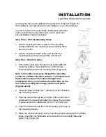
Страница 10: ...mounting bracket Drill this hole and install the screw after final testing and adjustments have been completed...

Страница 11: ...erference If the cable is too short extension cables are available to extend the transducer cable up to a total of 50 15 m Call Humminbird Customer Support for more information Follow these steps to r...

Страница 12: ...unting Location Begin the transducer installation by determining where inside the hull to install the transducer Consider the following to find the best location Observe the outside of the boat hull t...

Страница 13: ...The transducer cannot transmit through air The water purges any air from between the transducer and the hull and fills any voids in the coarse fiberglass surface...

Страница 14: ...dry the mounting surface If the surface is excessively rough it may be necessary to sand the area to provide a smooth mounting surface Ensure the mounting area is clear and dry 3 Mix an ample quantit...

Страница 15: ...supplied hole cover The mounting surface should be adequately supported to protect the fishfinder from excessive wave shock and vibration and provide visibility while in operation The mounting area sh...

Страница 16: ...fuse in the connection If you must wire the control head directly to a battery be sure to install an inline fuse holder...

Страница 17: ...mounting surface mark and drill a 1 25mm hole centered between the four mounting holes Figure 22 Note if the cables must pass through the mounting surface at a different location drill the 1 25mm hol...

Страница 18: ...Optional If the cables pass outside the mounting bracket install the hole cover over the hole and fasten in place using the two 8 x 7 8 22mm wood screws Figure 24...

Страница 19: ...ll the excess cable from beneath the mounting surface so the connector holder aligns with the mounting holes on the front of the mounting bracket Figure 27 3 Snap the support plate to the rear of the...

Страница 20: ...rmal operation unless you choose another option If you do not press any button before the timer reaches 0 the normal operation screen is displayed If the boat is in water sonar data appears If the bot...

Страница 21: ...leshooting section of this manual If the unit is working properly gradually increase the boat speed to test high speed performance If the unit functions well at low speeds but begins to skip or miss t...

Страница 22: ...Factory Settings if no transducer is connected IMPORTANT A transducer must be connected to the Wide 3D Paramount in order to retain user settings selected when in simulator mode If no transducer is de...

Страница 23: ...information from both the left and right beams is shown Using the view button to toggle between the three main views gives you the maximum benefit of each type of view The 3D view gives you an excelle...

Страница 24: ...When this occurs an audible chirp is heard Depth water surface temperature and boat speed are displayed across the lower left part of the screen The active menu appears in the upper left of the displa...

Страница 25: ...two center beams provide information to draw the bottom depiction Using a narrower beam provides much more detailed information Also you have the ability to quickly switch back to the 3D view for a b...

Страница 26: ...e return When a sonar signal is reflected off the bottom back to the transducer there is often enough energy left in the signal to be reflected off the surface of the water back to the bottom a second...

Страница 27: ...udible error or multiple chirps will be heard POWER powers the Wide 3D Paramount up for normal operation When the unit is on POWER turns the unit off POWER can also be used to go directly into Simulat...

Страница 28: ...ans that the corresponding ARROW button can be used to affect the menu adjustment The ARROW buttons often can be used when no menu is on screen In these situations pressing the ARROW button affects th...

Страница 29: ...the sonar receivers The Wide 3D Paramount automatically adjusts the level of receiver sensitivity based on a number of factors including the depth of the water and the level of noise present Noise ca...

Страница 30: ...gins to affect new sonar information as it flows on screen If additional adjustment is needed the UP ARROW or DOWN ARROW can be pressed without having to first press MENU The Sensitivity setting is re...

Страница 31: ...manually and the Depth Range menu is still active most recently used further adjustment of the depth range can be achieved by simply pressing the appropriate UP or DOWN ARROW button The button press...

Страница 32: ...f the Zoom range Automatic Zoom is especially helpful when looking for structure or bottom detail The Automatic Zoom keeps the bottom in view even in quickly changing terrain Manual Zoom provides deta...

Страница 33: ...e Factory Setting is Off Use the DOWN ARROW to highlight On The menu will expand to show the current Depth Alarm setting Use the UP or DOWN ARROW to set the desired depth for alarm activation Once the...

Страница 34: ...nit is powered off Triplog Triplog provides a running log of information based on input from the Temp Speed sensor and an internal clock Since Triplog require information from the Temp Speed sensor to...

Страница 35: ...es a highly sophisticated system of displaying terrain from several different viewpoints The Perspective menu is available in 3D View or Combo view only Six different perspective viewpoints are availa...

Страница 36: ...level of contrast Eleven contrast settings 5 to 5 are possible The display contrast will change as the adjustment is made so the optimum level of contrast can easily be adjusted Use the ARROW buttons...

Страница 37: ...settings are remembered when the unit is powered off Transducer The Transducer option allows manual selection or identification of a non standard transducer The Wide 3D Paramount is designed to work w...

Страница 38: ...ng is remembered when the unit is powered off Menu Timing The amount of time a menu remains onscreen after the last button is pressed is variable The default is 3 seconds Users new to the menu system...

Страница 39: ...r 16 beams at the deepest point This number varies with the depth of the water Width of Beam is displayed in the 2D view only The numeric display of this width of coverage can be displayed or removed...

Страница 40: ...erful diagnostic tool which can aid in determining the cause of a problem To enable Diagnostic power the unit on and use the DOWN ARROW button to highlight the Diagnostic option on the initial screen...

Страница 41: ...ing input voltage problems The current input voltage will be displayed If voltage fluctuates or power supply in excess of 16 VDC or less than 10 VDC is suspected use the diagnostic screen to confirm i...

Страница 42: ...nt is designed to operate with the Six Beam transducer included standard with the product The standard transducer can be mounted on the transom of the boat or bonded to the inside of most fiberglass h...

Страница 43: ...olling motor mount a transom mount or a portable mount Note The Wide Side transducer can be connected directly to the Wide 3D Paramount through a Y cable or used in conjunction with the standard trans...

Страница 44: ...bottom is often not visible on screen Ranges of 15 30 60 and 120 feet are available Also Zoom is not possible in Wide Side mode and the Zoom menu is not available Experiment with the Wide Side transdu...

Отзывы:

Похожие инструкции для WIDE Paramount 3D