


information is displayed, so each update contains information gathered from several transmit and
receive cycles.
The Wide 3D Paramount uses advanced signal processing to evaluate these sonar returns. If a
return meets certain criteria, a fish symbol is assigned. There are three different size symbols
used to indicate the intensity of the sonar return. While signal intensity is a good indicator of
relative fish size, different species of fish have different sonar characteristics, so it is not always
possible to distinguish fish size between varying species. The signal intensity is "normalized" for
Using the 3D view
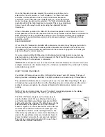
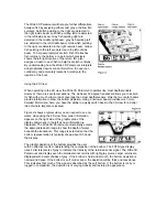
Figure F shows a typical view you can expect to see on-water. New sonar information appears on
the lower right of the display and moves to the left as new information is displayed. The Wide 3D
Paramount automatically selects the appropriate depth range to show the depth of water beneath
the transducer. This range is selected so that the bottom representation is typically shown about
2/3 down the display. The depth range is shown at the lower right of the display. As the depth of
the water changes, the Wide 3D Paramount automatically adjusts the depth range as necessary
to view the bottom on-screen. When this occurs an audible chirp is heard.
Depth, water surface temperature, and boat speed are displayed across the lower left part of the
screen. The active menu appears in the upper left of the display. The boat icon appears in the
upper right corder of the display and represents the location of the user’s boat relative to the on-
screen information. The location of the boat icon will change if the user changes the perspective.
(see control functions)
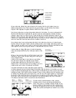
The graphic depiction of the bottom provides the user with
an effective tool for understanding the terrain beneath the
boat. Each of the six sonar beams transmits a signal at a
rate of about four time per second. The returned signals
from each transmit are compared and evaluated before
the information is displayed, so each update contains
information gathered from several transmit and receive
cycles.
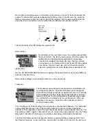
The Wide 3D Paramount uses advanced signal
processing to evaluate these sonar returns. If a return
meets certain criteria, a fish symbol is assigned. There
are three different size symbols used to indicate the
intensity of the sonar return. While signal intensity is a good indicator of relative fish size, different
species of fish have different sonar characteristics, so it is not always possible to distinguish fish
size between varying species. The signal intensity is “normalized” for depth so a small fish close
to the boat does not appear as a large fish symbol.
Содержание WIDE Paramount 3D
Страница 1: ......
Страница 8: ......
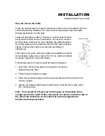
Страница 10: ...mounting bracket Drill this hole and install the screw after final testing and adjustments have been completed...


