background image

Bottom Black 
 
The next Option menu is Bottom Black. There are two 
selections available; Off and On. The factory setting is Off. 
With this setting, the ProAngler displays the bottom using 
Structure ID. This allows the user to determine the texture or 
relative hardness of the bottom. Selecting Bottom Black "ON", 
will cause the unit to blacken in the display below the bottom. 
This gives the user easiest recognition of the bottom location, 
even from a great distance. 
 
The ProAngler remembers the Bottom Black setting when 
powered oft. 


Diagnostic 

 
Diagnostic is the next Option menu. Two options are available: Hide and 
Show. The factory setting is Hide. Selecting Show brings up the 
Diagnostic screen. See the Using Diagnostic section for more information. 


Reset 
 
The final Option is Reset. With so many User Options available to customize 
the ProAngler, it is easy to configure the unit in such a way that it is detrimental 
to a particular use. By using the Reset function, all variable or user-controlled 
features of the ProAngler are returned to the factory settings. 
 
The Reset function is an important first step in trouble-shooting problems to 
ensure that a user selected setting is not the cause for the perceived problem. 
 
Use the ARROW buttons to highlight "Yes" and the unit will return to factory settings. After 
making the selection, press MENU to end Options and return to normal operation. 
USING DIAGNOSTIC 
 
The ProAngler contains a powerful diagnostic tool which can aid in determining the cause of a 
problem. To enable Diagnostic, power the unit on and use the DOWN ARROW button to highlight 
the Diagnostic option on the initial screen. Diagnostic can also be accessed through the Options 
menu. (See Control Functions.) 
 
When selecting Diagnostic from the startup menu, the menu will time out and the first of two 
diagnostic screens will appear. Upon enabling diagnostic, the ProAngler will perform a self-test. 
This test confirms the operation of all internal circuitry. At the conclusion of the test, one of two 
messages will appear; "passed" indicates that the internal test discovered no failures. "Failed" 
indicates that a significant internal problem was discovered and the unit will require factory 

Содержание ProAngler

Страница 1: ......

Страница 2: ...our number listed in the Customer Support section INSTALLATION OVERVIEW Your Humminbird fishfinder consists of two primary components to install the control head and the transducer The control head c...

Страница 3: ...should the boat strike debris in the water or when trailering As an alternative to transom mounting it is possible on many fiberglass hulled boats to glue the transducer on the inside of the boat hull...

Страница 4: ...other surface Trolling Motor Mounting The standard transducer can also be adapted to mount on most trolling motors using a different accessory kit This accessory includes a bracket and hose clamp that...

Страница 5: ...minbird fishfinder The installation guide included on the next few pages provides detailed step by step instructions for installation of the control head and transducer For transom mount transducer in...

Страница 6: ...the propeller s This turbulent water is normally confined to areas immediately aft of ribs strakes or rows of rivets on the bottom of the boat and in the immediate area of the propeller s Figure 1 On...

Страница 7: ...g a 5 32 4mm bit drill the two holes to a depth of approximately 1 3cm On fiberglass hulls it is best to start with a smaller bit and use progressively larger drill bits to reduce the chance of chippi...

Страница 8: ......

Страница 9: ...urther adjustment may be necessary to refine the instillation after high speed testing 1 First adjust the pivot angle of the transducer body so its length is parallel with the length of hull of the bo...

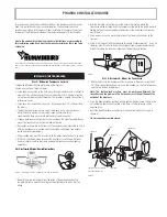
Страница 10: ...mounting bracket Drill this hole and install the screw after final testing and adjustments have been completed...

Страница 11: ...erference If the cable is too short extension cables are available to extend the transducer cable up to a total of 50 15 m Call Humminbird Customer Support for more information Follow these steps to r...

Страница 12: ...unting Location Begin the transducer installation by determining where inside the hull to install the transducer Consider the following to find the best location Observe the outside of the boat hull t...

Страница 13: ...The transducer cannot transmit through air The water purges any air from between the transducer and the hull and fills any voids in the coarse fiberglass surface...

Страница 14: ...dry the mounting surface If the surface is excessively rough it may be necessary to sand the area to provide a smooth mounting surface Ensure the mounting area is clear and dry 3 Mix an ample quantit...

Страница 15: ...supplied hole cover The mounting surface should be adequately supported to protect the fishfinder from excessive wave shock and vibration and provide visibility while in operation The mounting area sh...

Страница 16: ...fuse in the connection If you must wire the control head directly to a battery be sure to install an inline fuse holder...

Страница 17: ...mounting surface mark and drill a 1 25mm hole centered between the four mounting holes Figure 22 Note if the cables must pass through the mounting surface at a different location drill the 1 25mm hol...

Страница 18: ...Optional If the cables pass outside the mounting bracket install the hole cover over the hole and fasten in place using the two 8 x 7 8 22mm wood screws Figure 24...

Страница 19: ...ll the excess cable from beneath the mounting surface so the connector holder aligns with the mounting holes on the front of the mounting bracket Figure 27 3 Snap the support plate to the rear of the...

Страница 20: ...rmal operation unless you choose another option If you do not press any button before the timer reaches 0 the normal operation screen is displayed If the boat is in water sonar data appears If the bot...

Страница 21: ...imately 3 seconds until a continuous chirp is heard The Simulator can also be enabled by selecting the Simulator option on the start up screen after you normally power up the unit When this screen is...

Страница 22: ...display and moves to the left as new information is displayed The ProAngler automatically selects the appropriate depth range to show the depth of water beneath the transducer This range is selected s...

Страница 23: ...uous nature of the return ID adds an additional piece of information to help the user locate fish On selected fish symbols the digital depth of the designated fish is drawn to help locate the fish ver...

Страница 24: ...a good indicator of relative fish size different species of fish have different sonar characteristics so it is not always possible to distinguish fish size between varying species The signal intensit...

Страница 25: ...while the adjustment is made and times out A frequently used menu can be adjusted very quickly using this technique After an adjustment is made to a menu function the menu times out after a few secon...

Страница 26: ...ars use the UP ARROW to increase the sensitivity bias or the DOWN ARROW to reduce sensitivity bias By holding either ARROW button depressed the unit will sequence through the available settings until...

Страница 27: ...Range is selected manually and the Depth Range menu is still active most recently used further adjustment of the depth range can be achieved by simply pressing the appropriate UP or DOWN ARROW button...

Страница 28: ...ing the DOWN ARROW again to highlight Manual activates Manual Zoom The menu further expands to show the current Zoom range and allows user adjustment of this range When the range is shown in the menu...

Страница 29: ...to highlight Off Fish Alarm The Fish Alarm alerts you to the presence of fish or other targets not connected to the bottom The Fish Alarm has 3 different settings which correspond to the 3 different...

Страница 30: ...le application or whenever the ProAngler is operated from a battery source the voltage number can be used to determine battery life The ProAngler will operate at voltages from 10 to 20 VDC Voltages in...

Страница 31: ...cremental changes enhances the fishfinder s ability to identify sonar returns as fish symbols Increasing the value to a number greater than zero will show more fish symbols on screen In this case smal...

Страница 32: ...atures of the ProAngler are returned to the factory settings The Reset function is an important first step in trouble shooting problems to ensure that a user selected setting is not the cause for the...

Страница 33: ...ected message will appear Note This feature only works when the boat is in motion as the paddle wheel on the speed sensor must rotate to be detected The voltage input category is especially helpful in...

Отзывы: