background image

1

HOW SONAR WORKS

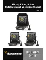
Sonar technology is based on sound waves. The ICE Flasher Series™ Fishfinder uses
sonar to locate structure, bottom composition, as well as depth directly below the
transducer. Your ICE Flasher Series™ Fishfinder consists of two components: the control
head and the transducer. The control head contains the transmitter and receiver, as well
as the user controls and display. The transducer is suspended beneath the water,
underneath the ice, and converts electrical energy from the transmitter into mechanical
pulses or sound waves. The transducer also receives the reflected sound waves and
converts them back into electrical signals for display on the Flasher Dial.

NOTE:

The transducer must be submerged in water for reliable transducer detection. The

bottom of the transducer should be even with the bottom of the ice or hang slightly below
the bottom of the ice.

Your ICE Flasher Series™ Fishfinder sends a sound wave signal and determines distance
by measuring the time between the transmission of the sound wave and when the
sound wave is reflected off of an object; it then uses the reflected signal to interpret
depth, size, and composition of an object.

Sonar is very fast. A sound wave can travel from the surface to a depth of 240 ft (70 m)
and back again in less than 1/4 of a second.

SONAR is an acronym for SOund and
NAvigation Ranging. Sonar utilizes precision
sound pulses or “pings” which are emitted
into the water in a teardrop-shaped beam.
The sound pulses “echo” back from objects
in the water such as the bottom, fish and
other submerged objects. The returned
echoes, or signals, are displayed as colored
lines on the Flasher Dial.

Real Time Sonar

Instant Display

Содержание ICE Flasher 55

Страница 1: ...ICE 35 ICE 45 ICE 55 Installation and Operations Manual 531611 1_A...

Страница 2: ...be used as a navigational aid to prevent collision grounding boat damage or personal injury When the boat is moving water depth may change too quickly to allow time for you to react Always operate the...

Страница 3: ...ging and Installing the Battery 9 3 Assembling the Portable Bag ICE 45 55 Only 11 Transducer Installation 12 1 Testing the Transducer Prior to Installation 12 2 Assembling the Transducer and Float 12...

Страница 4: ...ntinuous Depth Display in Very Shallow Water 33 Screen Fades Images are Not Sharp 33 2 Year Limited Warranty 34 Humminbird Service Policy 35 Returning Your Unit for Service 36 Specifications 37 Contac...

Страница 5: ...ransducer detection The bottom of the transducer should be even with the bottom of the ice or hang slightly below the bottom of the ice Your ICE Flasher Series Fishfinder sends a sound wave signal and...

Страница 6: ...the frequency and coverage of your sonar 455 kHz provides narrow coverage with the greatest definition 240 kHz provides wider coverage and a good balance between depth performance and resolution The...

Страница 7: ...bottom and provide high definition The 9 degree center beam provides the highest definition while the 19 degree beam provides wider coverage Depth capability is affected by such factors as bottom har...

Страница 8: ...immediately displayed on the Flasher Dial Depending on the size of the fish and its closeness to the transducer the sonar return will be displayed as a weak medium or strong sonar signal In the above...

Страница 9: ...g your ICE Flasher Series Fishfinder Please make sure that the following parts are included for your ICE Flasher Series control head ICE Flasher Series control head Portable base and handle Power cabl...

Страница 10: ...r each flat head screw and set aside 2 Insert a nut into the keyed space of each cable retention arm Push down on the nut until it is flush with the surface of the cable retention arm 3 Slide one cabl...

Страница 11: ...n each side to attach the handle to the base see the illustrations Installing the Handle Onto the Base and Sliding in the Handle Hand tighten only NOTE The handle is keyed so that it only fits onto th...

Страница 12: ...Place the control head into the gimbal bracket located on the base 2 Place the 1 diameter black washers as shown in the figure then thread the gimbal knob through the bracket and washers into the hou...

Страница 13: ...charger will turn green when the battery is fully charged NOTE Some international models may not include a battery or battery charger NOTE The battery charger uses a yellow LED to indicate it is char...

Страница 14: ...ry and connect both ends of each strap over the top Make sure that the straps are pulled tight around the battery and that the battery is seated securely in the battery well 6 Slide the Battery Termin...

Страница 15: ...of the portable bag 2 Insert the base handle assembly into the portable bag so that the Flasher Dial is facing out of the bag For best results pull the bag over one shoulder of the handle at a time 3...

Страница 16: ...ice hole If the transducer is working properly you will see the bottom displayed on the Flasher Dial as a red line WARNING Before walking onto the ice make sure that conditions are safe 2 Assembling t...

Страница 17: ...sure that the support cable is taut so that the transducer hangs straight down see illustration 5 If you would like to keep the support and signal cables together above the float stop attach a cable...

Страница 18: ...e appropriate terminal slot on the rear of the control head NOTE The slots are keyed to prevent reversed installation so be careful not to force the connector onto the holder 2 Route the transducer si...

Страница 19: ...You do not have to detach the transducer cable from the control head to store the transducer CAUTION Although the transducer signal cable is designed to be flexible in cold temperatures you must stor...

Страница 20: ...uto or x1 to power on the control head NOTE If the unit does not power up make sure that the connector is fully seated in the back of the control head the power cable is connected to the battery and t...

Страница 21: ...you see on the Flasher Dial and Active Display Refer to the following illustration and see Key Functions for more information Flasher Dial Zoom Key 1 6 Range Scale ICE 35 Active Display ICE 45 55 Gain...

Страница 22: ...keypad to control all user functions In addition multiple color palettes are available depending on your model Sonar return signals are displayed as colored lines on the Flasher Dial The color and th...

Страница 23: ...hese sonar return signals can indicate your jig bait fish and other fish swimming into the water column The color of the lines indicating the strength of the sonar return signal will vary depending on...

Страница 24: ...ow shows the many features that are available on the Active Display and where each feature will be displayed when you activate it NOTE Actual depth capability depends on such factors as bottom hardnes...

Страница 25: ...the best range based on the actual depth of the bottom A Auto setting is not available on the ICE 35 Manual Ranges Selecting a manual range allows you to choose a specific range For example if you onl...

Страница 26: ...dial Press a function key such as Gain Then turn the Selection dial to choose a setting for that function Press the Selection dial to complete your selection NOTE If you turn the Selection dial witho...

Страница 27: ...sher Dial between the two blue zoom lines On the ICE 45 55 Flasher the tick marks shown on the Active Display show the zoom area NOTE If you do not press the Selection dial within 5 seconds of pressin...

Страница 28: ...ete your selection NOTE If you do not press the Selection dial within 5 seconds of pressing the Gain key or turning the Selection dial the gain select function will time out NOTE If your control head...

Страница 29: ...al to choose a particular noise rejection setting then press the Selection dial to complete your selection NOTE If you do not press the Selection dial within 5 seconds of pressing the Noise key or tur...

Страница 30: ...esolution NOTE Your other option is to use the Noise key to reduce cross talk interference see Noise Rejection for more information 1 Press the Beam key to toggle between 240 kHz and 455 kHz ICE 35 Th...

Страница 31: ...in red lines on the Flasher Dial In Palette 1 Red indicates a strong sonar return signal Yellow Medium Signal Small objects such as fish sparse vegetation or soft bottom sand or mud are usually displa...

Страница 32: ...Flasher Dial In Palette 2 Green indicates a medium sonar return signal Yellow Weak Signal Light objects such as your jig bait fish sparse vegetation and sometimes microscopic activity or turbulence ar...

Страница 33: ...ellow indicates a medium sonar return signal Light Green Fairly Weak Signal Indicates a sonar return signal with an intensity in between Yellow and Green Green Weak Signal Light objects and softer bot...

Страница 34: ...rn the Selection dial and position the purple Target line to the depth you want to read The depth reading of the target line location will be shown on the Active Display NOTE When the Target function...

Страница 35: ...left on the battery The battery status will display on the Flasher Dial for approximately 5 seconds and then the Flasher Dial will resume Normal operation ICE 35 The percentage of battery power is ind...

Страница 36: ...non abrasive mild cleaner Do not wipe while dirt or grease is on the lens Be careful to avoid scratching the lens WARNING Never leave your ICE Flasher Series Fishfinder in a closed car or trunk the e...

Страница 37: ...al and black to negative terminal or ground the battery voltage of the power connector is between 10 5 and 20 VDC Correct any known problems including removing corrosion from the battery terminals or...

Страница 38: ...installation other than that recommended in the product installation and operation instructions Damaged or has failed because of an accident or abnormal operation Repaired or modified by entities othe...

Страница 39: ...service charge will be assessed for each repair physical damage and missing parts are not included Any repairs made after the original warranty will be warranted for an additional 90 days after servi...

Страница 40: ...Repair Authorization Number from the Humminbird Customer Resource Center Tag product with your name street address phone number and your assigned Repair Authorization Number Include a brief written de...

Страница 41: ...ucer XI 9 19 Transducer Cable Length 8 ft 2 4m NOTE Humminbird verifies maximum stated depth in saltwater conditions but actual depth performance may vary due to transducer installation water type the...

Страница 42: ...in hazardous substances in electrical and electronic equipment WEEE STATEMENT Product designed and intended as a portable and or fixed installation is considered in the scope of Directive 2002 96 EC o...

Страница 43: ...39 NOTES...

Страница 44: ...ys By Telephone Monday Friday 8 00 a m to 4 30 p m Central Standard Time 1 800 633 1468 By e mail typically we respond to your e mail within three business days cservice johnsonoutdoors com For direct...

Отзывы: