28
Installing the antenna and radio assembly
1037749-0001 Revision F
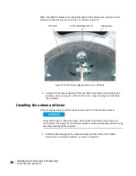
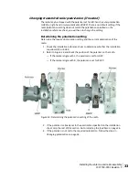
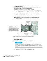
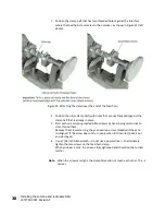
When the reflector bracket is correctly attached to the Az/El mount, you can see the
tilt scale numbers above the tilt pointer, as shown in Figure 10.
Figure 10: Tilt pointer aligned with zero on tilt scale
7.
Using the tilt value you obtained from the IDU as described in
Determining the
pointing values
on page 25, set the scale to the proper reading, and lock down
the five bolts.
Installing the antenna reflector
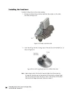
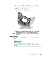
Follow the steps below to attach the antenna reflector to the reflector bracket.
While attaching the reflector bracket, do not place the reflector face down on a
hard surface. The weight of the reflector bracket and any additional pressure during
assembly could bend the reflector.
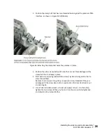
1.
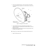
Hold the reflector against the reflector bracket so the hole for the Phillips
head screw is nearest the bottom, as shown in Figure 11.


