Chapter 4 • Installing a J-type radio assembly
1037312-0001 Revision B
37
Attaching the feed horn and
transition to the
radio assembly
The feed horn and waveguide transition are shipped from the
factory pre-attached, as shown in Figure 28.
Attach the square end of the waveguide transition (with the feed
horn attached) to the radio assembly—specifically, to the
transmit/receive isolation assembly, or TRIA:
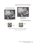
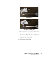
1. Apply silicone grease to the O-ring groove in the waveguide
transition. See Figure 29.
The silicone grease is provided in a small plastic capsule.
2. Place the O-ring (1-inch inside diameter) in the O-ring
groove in the square end of the waveguide transition.
Figure 28: Feed horn with waveguide transition attached
O-ring
groove
Waveguide
transition
Note:
The O-ring and small hardware for the square end of
the waveguide transition are shipped in a bag that contains
four socket-head cap screws.
Figure 29: O-ring in groove in waveguide transition
O-ring
Содержание AN6-098P
Страница 1: ...1037312 0001 Revision B October 21 2009 Installation Guide for 0 98 m Ku band Antenna Model AN6 098P ...
Страница 6: ... Contents vi 1037312 0001 Revision B ...
Страница 10: ... Tables x 1037312 0001 Revision B ...
Страница 22: ...Chapter 1 Overview 6 1037312 0001 Revision B ...
Страница 46: ...Chapter 3 Assembling the antenna 30 1037312 0001 Revision B ...
Страница 58: ...Chapter 4 Installing a J type radio assembly 42 1037312 0001 Revision B ...
Страница 72: ...Chapter 6 Cabling and connections 56 1037312 0001 Revision B ...
Страница 92: ...Chapter 7 Pointing the antenna 76 1037312 0001 Revision B ...
Страница 94: ... Acronyms and abbreviations 78 1037312 0001 Revision B ...
Страница 98: ... Index 82 1037312 0001 Revision B ...


