


•
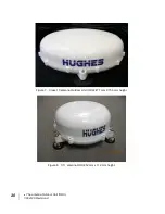
The antenna Outdoor Unit (ODU)
3004129 Revision A
21
Antenna cable lengths
and types
The Hughes IDU has an automatic cable calibration feature that
determines the dB loss of the cable. The RF cable that comes
standard in the terminal kit is 8 meters long. If a longer cable is
required for the installation, the end-to-end RF loss needs to be
<10 dB at 1.6 GHz and the cable must be 50 Ohm impedance.
Note: The installer is responsible for choosing the proper type
of cable for the length required in order to meet the <10 dB
requirement.
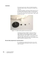
Installing the antenna
Avoid exposure to microwave radiation. Keep a minimum safe
distance of 1 meter (39 inches) to the side and above the antenna.
The antenna cable carries DC power.
Always power the IDU
down prior to connecting or disconnecting the antenna cable from
either the antenna or the IDU.
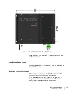
The antenna port is a 50 Ohm female TNC. This line carries RF,
signaling, and DC power for the antenna.
Keep a clear line-of-sight to the satellite. Preferably, avoid all
obstructions within 3 meters of the antenna. Obstructions less
than 150 mm (6 inches) in diameter can be ignored beyond this
distance.
It is important to ensure that there is a clear line-of-site to the
satellite.
Do not locate the antenna close to interfering signal sources or
receivers. It is recommended that no other antennas be located
within 3 meters of the 9450 antennas. If there is other equipment
installed near the Hughes 9450 mobile satellite terminal, it is
recommended to operate all equipment simultaneously and
verify there is no co-interference.
Содержание 9450 Series
Страница 1: ...Hughes 9450 Mobile Satellite Terminal Installation Guide 3004129 Revision A September 15 2010 ...
Страница 4: ...iv Contents 3004129 Revision A ...
Страница 6: ...vi Figures 3004129 Revision A ...
Страница 8: ...viii Tables 3004129 Revision A ...
Страница 15: ... Introduction 3004129 Revision A 5 Figure 3 Inserting SIM card in the SIM card holder ...
Страница 16: ...6 Introduction 3004129 Revision A ...
Страница 18: ...8 System power requirements 3004129 Revision A ...
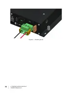
Страница 20: ...10 Standard cable connections 3004129 Revision A Figure 4 Chassis ground ...
Страница 22: ...12 Package materials 3004129 Revision A ...
Страница 28: ...18 Vehicular installation 3004129 Revision A ...