


•
Vehicular installation
3004129 Revision A
13
Chapter 5
Vehicular installation
Basic installation
procedure
The basic installation procedure is as follows:
1.
Decide where you are going to install the antenna and
IDU.
2.
Ensure that the IDU is located inside the vehicle and
attached to something structurally solid. Loose mounts that
vibrate will degrade performance.
3.
Determine the cable length required for the power
installation.
4.
Perform the installation of the antenna and IDU.
5.
Connect the antenna via the three magnetic mounts to the
vehicle’s roof or permanently mount using screws/bolts.
6.
Connect the RF cable to both the IDU and antenna TNC
connectors
7.
Connect the power to the IDU.
8.
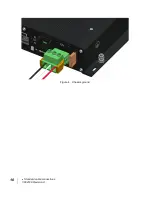
Properly ground the IDU
9.
Power up the IDU/antenna
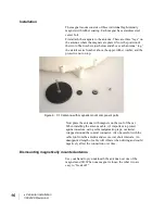
Installation notes
1.
Whenever routing cable through holes drilled in metal or
through bulkheads, use grommets and RTV sealant to
weatherproof all holes drilled on the outside of the vehicle.
2.
Use cable ties every 300 – 450 mm (12"-18").
3.
The IDU can be mounted in either the horizontal or
vertical position.
4.
The main power line must be connected to a fused 12 or
24 Vdc power source. The unit is fused, but a 15 A or
greater fuse is required in the source to protect against
shorts in the cabling. If connecting to a circuit in the fuse
box that is already in use, ensure that the circuit can supply
the extra 12 A at 12 V or 7.5 A at 24 V for the unit. If
using the car adapter cable, it already includes the fuse in
the adapter.
5.
Route and connect the white ignition sense wire to a
switched 12 or 24 Vdc source.
6.
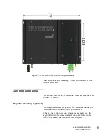
Ground the IDU to the vehicle via a wire connected to the
IDU chassis ground. See Figure 4.
Содержание 9450 Series
Страница 1: ...Hughes 9450 Mobile Satellite Terminal Installation Guide 3004129 Revision A September 15 2010 ...
Страница 4: ...iv Contents 3004129 Revision A ...
Страница 6: ...vi Figures 3004129 Revision A ...
Страница 8: ...viii Tables 3004129 Revision A ...
Страница 15: ... Introduction 3004129 Revision A 5 Figure 3 Inserting SIM card in the SIM card holder ...
Страница 16: ...6 Introduction 3004129 Revision A ...
Страница 18: ...8 System power requirements 3004129 Revision A ...
Страница 20: ...10 Standard cable connections 3004129 Revision A Figure 4 Chassis ground ...
Страница 22: ...12 Package materials 3004129 Revision A ...
Страница 28: ...18 Vehicular installation 3004129 Revision A ...