4
P/N 211014
03/05
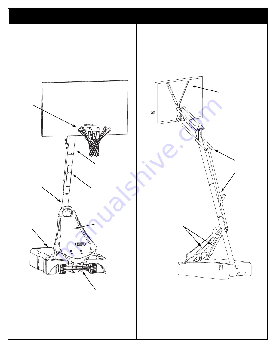
Get to know the basic parts of your basketball system...
FRONT VIEW
TOP POLE
BACK VIEW
MIDDLE
POLE
FRONT
COVER
RIM
BOTTOM
STRUTS
ELEVATOR
ASSEMBLY
BACKBOARD
BASE
WHEEL CARRIAGE
Страница 1: ...RUSSELL CORPORATION READ AND UNDERSTAND OPERATOR S MANUAL BEFORE USING THIS UNIT FAILURE TO FOLLOW OPERATING INSTRUCTIONS COULD RESULT IN INJURY OR DAMAGE TO PROPERTY WARNING 1 2 9 16 3 4 1 2 9 16 3...
Страница 2: ...th exterior enamel paint If rust has penetrated through the steel anywhere replace pole immediately Check system before each use for proper ballast loose hardware excessive wear and signs corrosion an...
Страница 3: ...lete assembly use and supervision are essential for proper operation and to reduce the risk of accident or injury A high probability of serious injury exists if this system is not installed maintained...
Страница 4: ...N 211014 03 05 Get to know the basic parts of your basketball system FRONT VIEW TOP POLE BACK VIEW MIDDLE POLE FRONT COVER RIM BOTTOM POLE STRUTS ELEVATOR ASSEMBLY BACKBOARD BASE WHEEL CARRIAGE ASSEM...
Страница 5: ...206948 Lower Pivot Bracket P 16 2 900122 Hinge Tubes P 17 2 900867 Triangle Plates Item Qty Part No Description P 18 1 207103 Pole Cap P 19 2 908169 Elevator Tube Lower P 20 2 904807 Elevator Tube Upp...
Страница 6: ...st basketball backboard height to lowest position 2 Rotate handle forward until wheels engage ground 3 Move basketball system to desired location 4 Rotate handle back to original position 5 Reattach g...
Страница 7: ...lock 1 2 13 H 16 2 203053 Bolt Carriage 5 16 18 x 4 Long H 17 4 202862 Spacer Plastic 50 O D 1 19 Long Item Qty Part No Description H 18 8 204847 Bolt Hex 1 2 13 x 9 5 Long H 19 1 201139 Bolt Hex 1 2...
Страница 8: ...tem H 6 1 Item H 8 1 Item H 12 1 Item H 18 8 Item H 19 1 Item H 31 1 Item H 25 2 Item H 21 2 Item H 29 4 Item H 3 1 Item H 10 1 Item H 16 2 Item H 27 4 Item H 13 4 Item H 2 1 Item H 30 1 HARDWARE IDEN...
Страница 9: ...Item H 4 7 Item H 15 8 HARDWARE IDENTIFIER NUTS WASHERS METAL SPACERS HARDWARE IDENTIFIER PLASTIC SPACERS CAPS Item H 14 2 Item H 9 4 Item H 33 1 Item H 11 17 Item H 1 4 Item H 17 4 Item H 22 1 Item...
Страница 10: ...CATION STICKER IS LOCATED 5 FROM THE END OF THE POLE WHEN PROPERLY POUNDED TOGETHER THE POLE SECTIONS SHOULD HAVE A 3 1 2 MINIMUM OVERLAP LEAVING 1 1 2 BETWEEN THE OVERLAPPING POLE AND THE IDENTIFICAT...
Страница 11: ...INIMUM OVERLAP NOTE HOLE DIMPLE Bottom pole THE IDENTIFICATION STICKER IS LOCATED 5 FROM THE END OF THE POLE WHEN PROPERLY POUNDED TOGETHER THE POLE SECTIONS SHOULD HAVE A 3 1 2 MINIMUM OVERLAP LEAVIN...
Страница 12: ...wheel bracket P 4 Secure wheels P 28 to axle using pushnuts H 1 Carefully tap pushnuts H 1 onto axle with hammer or mallet P 4 P 28 P 28 H 1 H 1 P 5 TO INSTALL SECOND PUSHNUT Assemble Pushnut Wheels...
Страница 13: ...211014 3 Install rod H 5 through holes in bottom pole section P 3 and eyebolt H 6 2 Install wheel assembly to base P 8 using bolt H 2 and nut H 11 as shown Finger tighten only H 6 H 5 P 1 P 3 P 2 H 2...
Страница 14: ...W THIS WARNING COULD RESULT IN SERIOUS INJURY AND OR PROPERTY DAMAGE WARNING Insert pole assembly into tank P 8 and through center hole on wheel assembly as shown Secure pole assembly with anchor stra...
Страница 15: ...cover H 7 over exposed end of bolt as shown Rotate non secured ends of tank struts P 13 outward to mounting holes in tank as shown TWO PEOPLE REQUIRED FOR THIS PROCEDURE FAILURE TO FOLLOW THIS WARNING...
Страница 16: ...H 4 P 13 H 26 H 9 P 14 H 8 TWO PEOPLE REQUIRED FOR THIS PROCEDURE FAILURE TO FOLLOW THIS WARNING COULD RESULT IN SERIOUS INJURY AND OR PROPERTY DAMAGE WARNING Insert bolt H 10 through lower pivot bra...
Страница 17: ...ing pushnuts H 1 Carefully tap pushnuts onto axle with hammer or mallet Secure both hinge tubes P 16 to second wheel bracket P 4 with carriage bolts H 13 and flange nuts H 11 P 4 H 11 P 16 9 P 16 H 13...
Страница 18: ...osition entire assembly as shown 11 TWO PEOPLE REQUIRED FOR THIS PROCEDURE FAILURE TO FOLLOW THIS WARNING COULD RESULT IN SERIOUS INJURY AND OR PROPERTY DAMAGE WARNING IMPORTANT DO NOT OVER TIGHTEN 12...
Страница 19: ...SYSTEM BACKBOARD This is what your system will look like when you ve finished this section Securely rest the assembly on sawhorse Identify elevator tubes P 19 and P 20 P 19 Lower Elevator Tube Toward...
Страница 20: ...P 17 and elevator tubes P 19 and P 20 to top pole section P 1 as shown Install pole cap P 18 at this time P 17 COMPLETED ASSEMBLY H 17 H 17 TWO PEOPLE REQUIRED FOR THIS PROCEDURE FAILURE TO FOLLOW THI...
Страница 21: ...ep as shown P 21 H 24 H 24 H 25 H 25 H 26 H 26 Assemble brackets P 21 to backboard using bolts H 25 metal spacers H 24 and nuts H 26 as shown The spacers may fit very tightly between the brackets and...
Страница 22: ...s shown 5 P 21 H 20 H 15 H 20 H 22 P 12 H 22 P 12 6 P 19 H 31 P 30 H 29 H 11 IMPORTANT Position springs P 12 against elevator tubes as shown Insert T bolt H 31 into Slam Jam bracket P 30 then attach t...
Страница 23: ...securely into bracket P 30 as shown Allow T bolt H 31 to slip through center hole in rim P 29 B Install reinforcement bracket P 31 onto T bolt H 31 as shown C Install spring P 32 onto T bolt H 31 as...
Страница 24: ...H 18 H 20 P 21 H 15 H 20 Assemble upper elevator tubes P 20 to brackets using bolt H 18 plastic spacers H 20 and nut H 15 as shown 8 P 19 P 19 TIGHTEN BOLT H 18 IN LOCK NUT H 15 UNTIL FLUSH EVEN WITH...
Страница 25: ...dle assembly P 10 P 11 to pole bracket P 9 using bolt H 30 and nut H 23 as shown 10 P 9 P 7 H 30 H 23 P 10 IMPORTANT Note orientation of handle Before going on to next step set adjustable system assem...
Страница 26: ...hen stretch spring P 12 onto bolt H 18 Continue inserting bolt H 18 through right side upper elevator tube P 20 and secure with nut H 15 H 18 P 12 USE EYE PROTECTION WHEN INSTALLING SPRINGS WARNING IM...
Страница 27: ...direction indicated by arrows Push second arm back and into ram as shown Twist body of clip slightly again to spread arms of clip Clip arms must be flat and touching edge to edge as shown without over...
Страница 28: ...211014 03 05 Insert net into bottom of clip as shown SIDE VIEW Twist net until it snaps into position Net must be centered through clip NET NET CLIP SIDE VIEW NET NET CLIP 13 H 28 P 33 Install net P 3...
Страница 29: ...ns and snap fill cap P 24 in place P 24 2 DO NOT LEAVE ASSEMBLY UNATTENDED WHEN EMPTY IT MAY TIP OVER WARNING ADD TWO GALLONS 7 6 LITERS OF NON TOXIC ANTIFREEZE IN SUB FREEZING CLIMATES CAUTION TWO PE...
Страница 30: ...protective film from surface of acrylic backboard prior to use NOTE 204532 11 04 MOVING SYSTEM 1 Adjust basketball backboard height to lowest position 2 Rotate handle forward until wheels engage grou...