HUEDA LED SR-2108B-24M-3 Скачать руководство пользователя страница 5

5/8

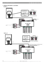
7. DMX/RDM terminal connection options 

1. XLR-3 parallel connection

XLR-3

RJ45

XLR-3

RJ45

XLR-3

RJ45

In

Out

In

Out

In

Out

2. RJ45 parrallel connection

XLR-3

RJ45

XLR-3

RJ45

XLR-3

RJ45

In

Out

In

Out

In

Out

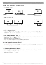
8. DMX address setting: 

Select menu                     and then click button “

Enter

”. Display will ash then click or hold button “

Up

” or “

Down

” to 

set DMX address, Click button“

Back

” to conrm.

XXX

9. DMX channel quantity setting: 

Select menu ,                     and then click button “

Enter

”. Display will ash, then click button “

Up

” or “

Down

” to set DMX 

channel quantity. Click button “

Back

” to  conrm.

For example the DMX address is already set as 001.
CH01=1 DMX address for all the output channels, which are all address 001.
CH24=24 DMX addresses, output 1-24 is address 001-024 respectively.

XX

10. PWM output resolution Bit setting:

Select menu               and then click button “

Enter

”.  Display  will ash, then click button “

Up

 or 

Down

” to choose 08 or 16 

bit. Click button “

Back

” to conrm.

XX

11. Output PWM frequency setting:

Select menu                             and then click button “

Enter

”.   Display will ash, then click button “

Up

 or 

Down

” to choose 

between 00~30. Click button “

Back

” to conrm.

 00=500Hz, 01=1KHz, 02=2KHz...........30=30KHz.

XX 

V- V- V+ V+

V- V- V+ V+

V- V- V+ V+

V- V- V+ V+

V- V- V+ V+

V- V- V+ V+

SR-2108B-24M-3 DMX512 Decoder

HUEDA

 LED | CALGARY, AB | CANADA 

Copyright © 2017 HUEDA™ LED, A division of LED World Inc.. All Rights Reserved. We are not responsible for errors or omissions. Product and specications subject to change without notice. Registered trademarks are owned by their respective registers, or licensee(s).

www.huedaled.com | 1-800-387-4081

Содержание SR-2108B-24M-3

Страница 1: ...sic installations Please carefully review your installation before proceeding Safety Warnings Before you begin read all warnings and installation instructions and save for future use 1 Product Feature...

Страница 2: ...1 channel then simultaneous fade down 100 0 of output 1 channel and fade up 0 100 of output 2 channel so on up to last channel Ca03 Fade up 0 100 of output 1 then output 2 output 3 output 24 output 1...

Страница 3: ...8 mm long solder tip tinned Do not allow Wires to cross and insure all exposed wire is fully inserted into the screw terminals Hand tighten screw terminals DC1 DC4 Power Input Use 13 10 AWG wire Outp...

Страница 4: ...wn Ground White Orange Data Orange Data D GND GND D Vin White Green VDC White Blue VDC class2 power input Option 2 Rj45 Cable Connectivity option for DMX Data Transfer Make sure that wires cannot cros...

Страница 5: ...address 001 CH24 24 DMX addresses output 1 24 is address 001 024 respectively XX 10 PWM output resolution Bit setting Select menu and then click button Enter Display will ash then click button Up or D...

Страница 6: ...FTWARE_VERSION_LABEL DMX_PERSONALITY DMX_PERSONALITY_DESCRIPTION SLOT_INFO SLOT_DESCRIPTION MANUFACTURER_LABEL SUPPORTED_PARAMETERS The data de nitions for strobe channel are as follows 0 7 unde ned 8...

Страница 7: ...tput 14 dimming output 19 dimming output 19 20 21 dimming output 21 dimming output 20 dimming output 17 dimming output 19 20 21 22 dimming output 19 dimming output 17 18 19 20 dimming output 19 dimmin...

Страница 8: ...h the purchase of products including but not limited to loss of data business markets cost of labour savings income profits use production reputation or goodwill anticipated or otherwise or economic l...

Отзывы: