


3/8
R
G
B
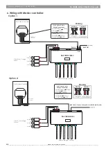
Output Port
RGB LED Lighting Fixtures
DMX/RDM Signal
DMX/RDM Signal
1
2
3
4
5
6
D
C3
D
C2
D
C1
DMX
IN
D
M
X
O
U
T
SR-2108B-24M-3
Class 2 regulated
(12~24VDC) driver
+
R
G
B
R
G
B
R
G
B
R
G
B
R
G
B
R
G
B
W
R
G
B
+
W
R
G
B
+
W
R
G
B
+
W
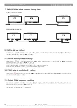
Single Color LED xture
CCT LED xture
RGB LED Fixture
RGBW LED Fixture
W
WW
R
G
B
R
G
B
-
+
W
Warning: Input voltage must be identical to output voltage of the LED Fixture!
Exposed wire should not be more than 6- 8 mm long & solder tip (tinned). Do not allow
Wires to cross and insure all exposed wire is fully inserted into the screw terminals. Hand
tighten screw terminals.
Ÿ
DC1~DC4 Power Input : Use 13~10 AWG wire
Ÿ
Output Terminals : Use 16~12 AWG wire
WIRE 6-8 MM (0.25-0.30")
5. RGB LED xture connection diagram:
SR-2108B-24M-3 DMX512 Decoder
HUEDA
™
LED | CALGARY, AB | CANADA
Copyright © 2017 HUEDA™ LED, A division of LED World Inc.. All Rights Reserved. We are not responsible for errors or omissions. Product and specications subject to change without notice. Registered trademarks are owned by their respective registers, or licensee(s).
www.huedaled.com | 1-800-387-4081


