UPS5000-S-1200 kVA
User Manual
2 Overview
Issue 04 (2019-06-25)
Copyright © Huawei Technologies Co., Ltd.
24
The optional backfeed protection card or dry contact extended card can be installed only in the control
module of the bypass unit.
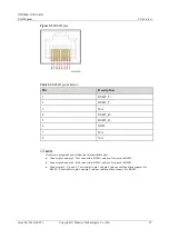
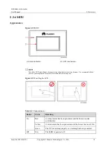
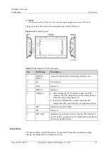
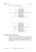
Figure 2-13
Signal panel on the control module
(1) Ground terminal
(2) Parallel port 1
(3) BSC port
1
(4) Ready switch
on ECM 1
(5) Indicators for ECM 1
(6) Parallel port 2
(7) BSC port
2
(8) Ready switch
on ECM 2
(9) Indicators for ECM 2
(10) Dry contact card
(11) Dry
contacts
(12) MDU port
(13) RS485 port
(14) Fast Ethernet (FE)
port
(15) COM2
port
(16) COM1 port
(17) Battery temperature
sensor port
(18) Optional card
subrack cover
Ports are protected by a security mechanism.
2.3.5.2 ECM
Appearance
The control module consists of two energy control modules (ECMs) in active/standby mode.
Figure 2-14
ECM
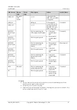
Table 2-4
Ports on the ECM
Silk Screen
Description


