

UPS5000-E-(30 kVA-120 kVA)-FM
User Manual
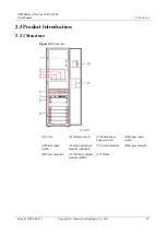
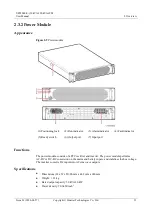
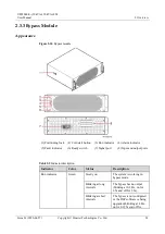
2 Overview
Issue 01 (2020-04-27)
Copyright © Huawei Technologies Co., Ltd.
32
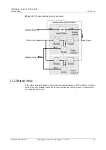
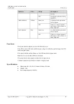
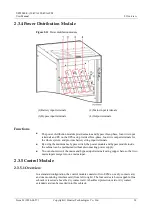
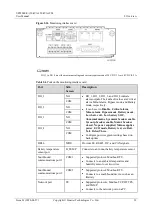
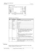
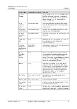
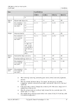
Figure 2-16
Monitoring interface card
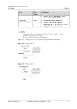
DO_1 to DO_4 meet the maximum voltage and current requirements of 30 V DC/1 A or 60 V DC/0.5 A.
Table 2-6
Ports on the monitoring interface card
Port
Silk
Screen
Description
DO_1
NO
DO_1, DO_2, DO_3, and DO_4 indicate
alarm outputs. Their default values are Critical
alarm, Minor alarm, Bypass mode, and Battery
mode, respectively.
It can be set to
Disable
,
Critical alarm
,
Minor alarm
,
Bypass mode
,
Battery mode
,
Low batt. volt.
,
Low battery SOC
,
Abnormal mains
,
Sys maint breaker enable
,
Sys outp breaker enable
,
Maint. breaker
closed
,
No power supplied
,
Mains supplies
power
,
ECO mode
,
Battery test
, and
Batt.
Volt. Below Thres.
.
Configure power segment settings based on
backup time.
COM
DO_2
NO
COM
DO_3
NO
COM
DO_4
NO
COM
DB26
MDU
Provides FE, RS485, I2C, and CAN signals.
Battery temperature
sensor port
B_TEMP
Connects to an indoor battery temperature sensor.
Southbound
communications port 1
COM1
Supported protocol: Modbus-RTU.
Connects to an ambient temperature and
humidity sensor over two wires.
Southbound
communications port 2
COM2
Supported protocol: Modbus-RTU.
Connects to a southbound device, such as an
iBattery.
Network port
FE
Supported protocols: Modbus-TCP, HTTPS,
and SNMP.
Connects to the network port on a PC.


