background image

Mains

input

Bypass

input

AC

load

K

m

1

Q1

K

b

1

8

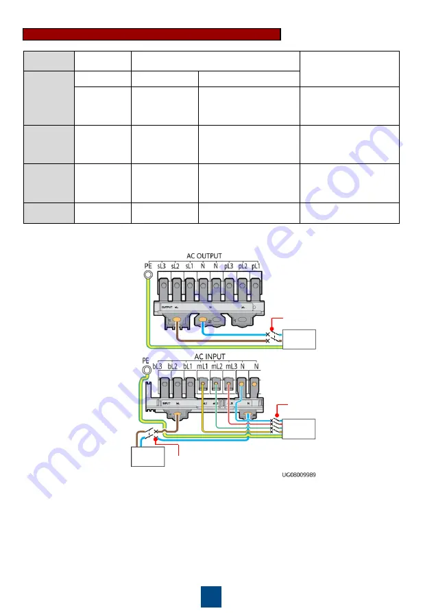
Wiring 

Terminal

AC OUTPUT

AC INPUT

PE

External 

Circuit 

Breaker

Q1

Mains K

m

1

Bypass K

b

1

15 kVA: 100 A 

(D feature); 

20 kVA: 125 A 

(D feature)

15 kVA: 50 A (D 

feature); 20 kVA: 

63 A (D feature)

15 kVA: 100 A (D feature); 

20 kVA: 125 A (D feature)

-

Residual 

Current 

Circuit 

Breaker

-

15 kVA: 300 mA; 

20 kVA: 300 mA

15 kVA: 300 mA; 20 kVA: 

adjustable from 500 mA 

to 1000 mA

-

Cable 

Cross-

Sectional 

Area

25 mm

2

10 mm

2

25 mm

2

25 mm

2

Terminal 

Type

OT-25 mm

2

-

M6 terminal

OT-10 mm

2

-M6 

terminal

OT-25 mm

2

-M6 terminal

OT-25 mm

2

-M6-90

°

terminal

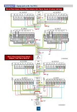
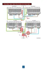
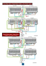
Three-Phase Input, Single-Phase Output, Two Power Sources

Содержание UPS2000-G-15KRTL

Страница 1: ...de Off The UPS is not working in battery mode Blinking The battery capacity is less than 25 4 Bypass indicator On The UPS is working in bypass mode Off The UPS is not working in bypass mode 5 Fault indicator INFO button Steady red The UPS is faulty Blinking red The UPS has generated an alarm Green The UPS is normal 6 Confirm Start button Confirms settings starts the UPS mutes the buzzer or perform...

Страница 2: ...ports 7 Parallel ports 8 Maintenance bypass port 9 EPO port 1 Carefully read the UPS2000 G 6 kVA 20 kVA User Manual prior to installation to get familiar with product information and safety precautions 2 Use insulated tools during installation 3 Only engineers certified by the manufacturer or its agent are allowed to install commission and maintain the UPS Otherwise personal injury or equipment da...

Страница 3: ...evices 1 Determine the installation dimensions UPS 3U Battery pack optional 3U Rack Mounted Installation Scena rio 1 Install devices from bottom to top as shown in the figure 2 Install mounting ears M4x8 8 PCS 1 2 N m ...

Страница 4: ...pushing guide rails out of the rack when placing the battery pack power distribution unit PDU and UPS on the rack because the front ends of the guide rails are not screwed The length of guide rails ranges from 592 37 mm to 807 37 mm the width is 30 mm and the height is 87 mm The guide rails are scalable and support Huawei M type cabinets Floating nut Front Rear M6x16 4 PCS 3 N m UPS 3 U 4 Secure t...

Страница 5: ...er bar and ground screws are M6 Tighten them to 4 8 N m The chassis screws are M5 Tighten them to 2 8 N m 7 In a single UPS system connect loads to AC OUTPUT sL and pL terminals Connect primary loads to the sL terminal and secondary loads to the pL terminal For a parallel system connect loads to the AC OUTPUT pL terminal instead of the sL terminal 8 The UPS can generate large leakage currents A ci...

Страница 6: ...using an OT 16 mm2 M6 90 terminal delivered with the UPS or an OT 10 mm2 M6 90 terminal prepared by the customer Mains input Bypass input AC load Km1 Q1 Kb1 If the customer uses 10 mm2 five core cables for AC input and output the PE cable is 10 mm2 In this case connect the cable using an OT 16 mm2 M6 90 terminal delivered with the UPS or an OT 10 mm2 M6 90 terminal prepared by the customer Wiring ...

Страница 7: ...ture 20 kVA 125 A D feature 15 kVA 50 A D feature 20 kVA 63 A D feature 15 kVA 100 A D feature 20 kVA 125 A D feature Residual Current Circuit Breaker 15 kVA 300 mA 20 kVA 300 mA 15 kVA 300 mA 20 kVA adjustable from 500 mA to 1000 mA Cable Cross Sectional Area 25 mm2 10 mm2 25 mm2 25 mm2 Terminal Type OT 25 mm2 M6 terminal OT 10 mm2 M6 terminal OT 25 mm2 M6 terminal OT 25 mm2 M6 90 terminal ...

Страница 8: ...e 20 kVA 63 A D feature 15 kVA 100 A D feature 20 kVA 125 A D feature Residual Current Circuit Breaker 15 kVA 300 mA 20 kVA 300 mA 15 kVA 300 mA 20 kVA adjustable from 500 mA to 1000 mA Cable Cross Sectional Area 25 mm2 10 mm2 25 mm2 25 mm2 Terminal Type OT 25 mm2 M6 terminal OT 10 mm2 M6 terminal OT 25 mm2 M6 terminal OT 25 mm2 M6 90 terminal Three Phase Input Single Phase Output Two Power Source...

Страница 9: ... 25 mm2 M6 terminal OT 25 mm2 M6 terminal OT 25 mm2 M6 90 terminal AC input AC load Q1 K1 Q1 K1 L1 L2 PE L1 L2 PE Wiring Terminal AC OUTPUT AC INPUT PE External Circuit Breaker Q1 K1 15 kVA 100 A D feature 20 kVA 125 A D feature 15 kVA 100 A D feature 20 kVA 125 A D feature Residual Current Circuit Breaker 300 mA Cable Cross Sectional Area 25 mm2 25 mm2 25 mm2 Terminal Type OT 25 mm2 M6 terminal O...

Страница 10: ...BATT 240 V DC External Circuit Breaker 63 A Cable Cross Sectional Area 16 mm2 Terminal Type OT 16 mm2 M6 90 terminal External Battery Strings Scenario 1 External Battery Packs Scenario 2 1 A 15 kVA 20 kVA UPS with long backup time requires serial connection of two battery packs in each group A maximum of four groups with eight battery packs can be connected in parallel If more than two battery pac...

Страница 11: ...k 8 4 Optional Connecting Cables to Optional Cards SNMP Card For details about how to install the SNMP card dry contact card and Modbus card see the RMS SNMP01A V100R001 Installation Guide RMS MODBUS01A User Manual and RMS RELAY01A User Manual Dry Contact Card Temperature and humidity sensor Ethernet Customer equipment ...

Страница 12: ...d Failed 2 The phase sequence of the input power is correct Use a multimeter to check that the input and output are not short circuited Passed Failed 3 Cables and terminals are securely connected Passed Failed 4 Battery cables and terminals are connected correctly and voltages comply with industry standards Passed Failed 5 The UPS is properly connected to battery strings Passed Failed 6 Input circ...

Страница 13: ...B Indicates omitted screens A A B 7 Powering On and Starting the UPS Powering On the UPS 7 1 Check that the UPS has passed all check items described in chapter 6 Verifying the Installation Switch on the external battery circuit breaker if any Switch on the upstream UPS mains and bypass circuit breakers K1 Km1 and Kb1 based on site requirements Start the UPS in normal or bypass mode No Cold start t...

Страница 14: ...ystem uses three phase input single phase output or single phase input single phase output set Output mode to Single phase Voltage level The values include 208 V 220 V default 230 V and 240 V for single phase output or 380 V default 400 V and 415 V for three phase output Set it based on site requirements Frequency level The values include 50 Hz default 60 Hz and Automatic Set it based on site requ...

Страница 15: ...uency level Set Voltage level The following uses three phase input and three phase output of the UPS in normal mode as an example The parameter setting screens are shown as follows Set Language default English System Parameters and Battery Parameters Incorrectly setting battery parameters compromises battery safety and battery backup time For details about parameter settings see the UPS2000 G 6 kV...

Страница 16: ...ar a beep sound The inverter shuts down If the bypass voltage is within the configured range the UPS transfers to bypass mode If the bypass voltage is beyond the configured range the UPS has no output 8 Shutdown 1 Shut down loads 2 Perform shutdown operations on the UPS The inverter shuts down and the UPS transfers to bypass mode If the bypass voltage is beyond the configured range the UPS has no ...

Страница 17: ...ystem Only UPSs of the same model can be connected in parallel UPS 3 U Battery pack optional 3 U PDU optional 3 U Rack Mounted Installation Scenario 1 When you tower mount the UPS place devices including the UPS horizontally to facilitate cable installation Stand the devices upright after cable installation UPS 3 U Battery pack optional 3 U Rubber plug Tower Mounted Installation Scenario 2 PDU opt...

Страница 18: ...o be provided by the customer 5 When UPSs are connected in parallel the output parallel power cables of each UPS must be at least 1 m long and the length deviation must be less than 10 The four cables must be connected at the remote end 6 If the parallel system uses the TN C power distribution system install magnetic rings around the PE cables on each UPS bind the magnetic rings together using cab...

Страница 19: ...nario 1 Three Phase Input Three Phase Output One Power Source Factory Settings AC input Q1 Q2 Q K K1 K2 AC load Three Phase Input Three Phase Output Two Power Sources AC load Mains input Bypass input Q1 Q2 Q Kb Km Km2 Km1 Kb2 Kb1 ...
Страница 20: ...20 Three Phase Input Single Phase Output One Power Source AC load AC input Q1 Q2 Q Km1 Km2 Kb1 Kb2 Km Kb ...

Страница 21: ...C load AC input K K1 Q Q2 Q1 K2 Three Phase Input Single Phase Output Two Power Sources AC load Mains input Bypass input Q1 Q2 Q Kb1 Kb Km1 Kb2 Km2 Km Single Phase Input Single Phase Output One Power Source ...
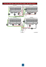
Страница 22: ...22 Dual Live Wire Input Dual Live Wire Output One Power Source AC load AC input K1 Q Q2 Q1 K K2 L2 L1 PE L1 L2 PE L2 L2 L1 L1 PE PE ...

Страница 23: ...ree Phase Output One Power Source Factory Settings PDC 0038V4ACIOA Three Phase Input Three Phase Output Two Power Sources PDC 0038V4ACIOA For details about the PDU see the PDC 0038V4ACIOA Quick Installation Guide or PDC 0091V2ACIOA Quick Installation Guide ...
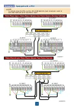
Страница 24: ...ree Phase Input Single Phase Output Two Power Sources When connecting cables between PDUs and the mains input of the UPS 1 and UPS 2 connect only L2 and L3 As L1 and N wires do not connect to the UPS wrap them with insulation tape PDC 0091V2ACIOA PDC 0091V2ACIOA ...

Страница 25: ...25 Single Phase Input Single Phase Output One Power Source PDC 0091V2ACIOA ...

Страница 26: ...andard configuration and an even number of 32 to 40 batteries are supported The neutral wire is connected to the middle point of the battery string For example if there are 40 batteries the neutral wire is connected to the negative terminal of the twentieth battery 2 When an external battery string is connected install a DC circuit breaker 63 A 600 V DC between the battery string and the UPS If a ...

Страница 27: ...h eight battery packs can be connected in parallel If the 15 kVA 20 kVA UPS with long backup time connects to more than two battery packs connect the battery packs in parallel and then to the UPS battery input port Connect battery packs 1 and 2 in series battery packs 3 and 4 in series battery packs 5 and 6 in series and battery packs 7 and 8 in series Connect battery packs 1 3 5 and 7 in parallel...

Страница 28: ...g shows how to install cables for the Modbus card UPS 1 UPS 2 RS232 RS485 adapter RS232 port on the PC 5 Optional Connecting an EPO Switch 1 For UPS2000 G 15KRTL 01 UPS2000 G 20KRTL 01 choose Settings System Parameters Other Settings and set EPO Enable to Enable 2 Connect an external switch to the EPO ports of the UPS After you turn on the switch in the case of emergency the inverter stops and the...

Страница 29: ...he parallel system by following instructions in chapter 6 Verifying the Installation 2 Check that parallel cables are properly connected and that the output voltages of all UPSs in the parallel system are consistent 3 Ensure that the output phases of all UPSs in the parallel system are the same ...

Страница 30: ...irements Check that the input voltage is normal Check that the initialization screen is displayed as shown in section 8 2 Powering On and Starting the UPS 8 1 Switch on output circuit breaker Q1 and keep output circuit breaker Q2 open Check that the voltage difference between the two ends of output circuit breaker Q2 is within 2 V Start the UPS inverter and then shut down the inverter so that the ...

Страница 31: ...code is 999999 used to restore the preset password Scenario 2 Non initial Startup Set Language default English System Parameters and Battery Parameters Scenario 1 Initial Startup UPS Initialization and Parameter Settings 8 2 The following uses three phase input and three phase output of the UPS in normal mode as an example The parameter setting screens are shown as follows 1 Set Language default E...

Страница 32: ... properly switch on the general AC output circuit breaker Q for the UPSs and start each load To prevent triggering overload protection start the loads with higher power and then loads with lower power After you perform startup operations on UPS 1 to UPS n one by one UPS 1 to UPS n are starting If you do not perform startup operations on the other UPSs in 5 minutes UPS 1 to UPS n enter normal mode ...

Страница 33: ...rallel system The inverters shut down If the bypass voltage is within the configured range the UPS transfers to bypass mode If the bypass voltage is beyond the configured range the UPS has no output 1 Shut down loads 2 Perform shutdown operations on each UPS in the parallel system The inverters shut down If the bypass voltage is within the configured range the UPS transfers to bypass mode If the b...

Страница 34: ...e may be abnormal Replace the faulty device If no wait until the mains recovers Check the mains input frequency If it is abnormal wait until the mains input recovers 0001 02 Minor 0001 03 Minor Abnormal BPS volt 0010 01 Minor Automatic The UPS cannot transfer to bypass mode If the UPS is working in bypass mode it transfers to another working mode Possible causes The bypass input voltage is abnorma...

Страница 35: ...rter has not started the output keeps disconnected and the inverter is not allowed to start If the inverter has started the UPS can work in inverter mode properly but the UPS cannot transfer to bypass mode Possible cause The bypass input three phase sequence is incorrect Measure Check that bypass input power cables are correctly connected Batt overvolt 0025 01 Minor Automatic An alarm is displayed...

Страница 36: ...t the transformer mode is not enabled The hardware is damaged Measures Rectify the fault and power on the UPS again Check that the loads are supported by the UPS Enable the transformer mode Contact Huawei technical support Internal fault 0042 10 Critical Automatic If the inverter has not started disable inverter startup If the inverter has started the UPS can work in inverter mode properly but the...

Страница 37: ...he inverter is faulty Measures Check whether other alarms are raised If other alarms are raised clear them If no alarm is raised start the UPS manually On battery 0159 01 Minor Automatic The UPS may power off if batteries are abnormal Possible causes The mains input is abnormal The UPS is in battery self check state The mains loading capability is insufficient Measures Check the mains input If it ...

Страница 38: ...hina www huawei com Scan here for more documents You can also log in to Huawei technical support website Support Support E WeChat HUAWEI AppGallery Scan here for technical support enterprise Scan here for technical support carrier HUAWEI AppGallery https support huawei com https support huawei com enterprise ...

Отзывы: