U8815
Maintenance Manual
4 PCBA Components
Issue 1.0 (2012-02-13)
Huawei Proprietary and Confidential
Copyright © Huawei Technologies Co., Ltd.
6
4
PCBA Components
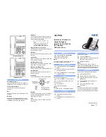
The following figures show the PCBA components.
Figure 4-1
PCBA components diagram 1
Failure caused by damage to
the J1001 headset connector
:
handset function failure
Failure caused by
damage to
the
U3202 RF switch
:
signal failure
Failure caused by
damage to
the
U3401 RF gain
module 824
–849
MHz
: signal failure
Failures caused by
damage to
the U6011
BCM4330
: FM, BT,
and Wi-Fi functions
cannot be used.
Failure caused by
damage to
the
U3101 19.2 MHz
crystal oscillators
:
power-on failure
Failures caused by
damage to
the U1700
Flash
: power-on failure
and software failure
Failures caused by damage to
the U401 baseband chip and
CPU
: power-on failure,
breakdown, and RF failure
Failure caused by
damage to
the U3501
power module
: GSM
transmission failure
Failures caused by
damage to
the
U4202RF power
module 1850
–1910
MHz
: no signal,
weak signal, and
registration failure
Failure caused by
damage to
the
U3302 RF gain
module 1920
–1980
MHz
: signal failure
Failure caused by
damage to
the
springs of the
J1026, J1205,
and J1204
volume keys
:
volume key failure
Failure caused by
damage to
the
U1402 compass
:
direction
orientation failure
Failure caused by
damage to
the
U1401 acceleration
meter
: gravity
induction failure