background image

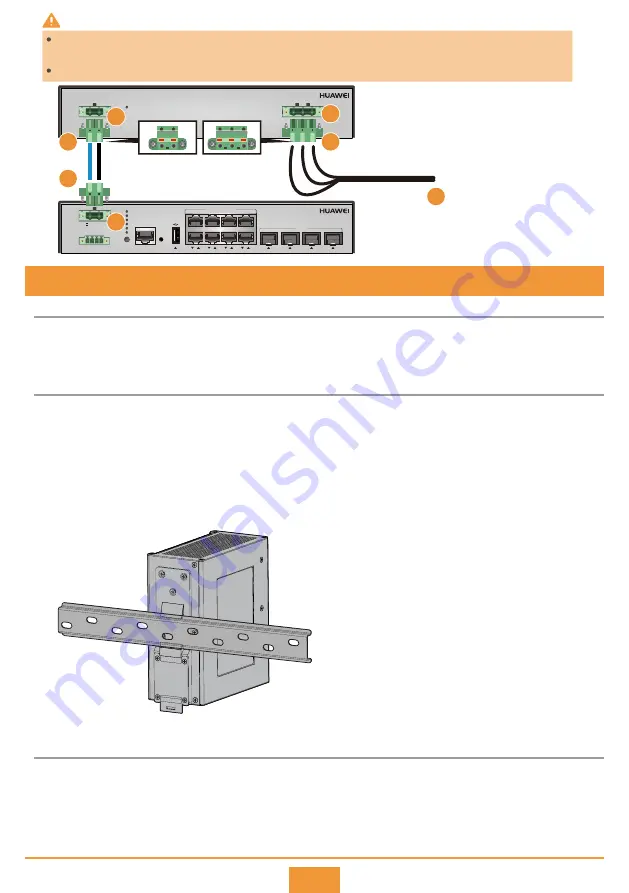
The PAC240S56-CN power module uses 220 V AC or 240 V DC input and provides four 56 V DC outputs. When 
the S5720I-12X-PWH-SI-DC is installed in a scenario where 220 V AC or 240 V DC power is provided, the 
PAC240S56-CN can be used to transfer power. 

Before You Start

8 (Optional) Installing the PAC240S56-CN Power Module

Installing the PAC240S56-CN Power Module

Connecting the switch to the PAC240S56-CN Power Module

Use a wire stripper to peel about 7 mm length of insulation coating off one end of the positive and negative 
cables. Insert the bare wires of the power cable into the Phoenix connector according to the sequence 
shown in the figure, and tighten the screws to lock the cable.

Step 1

Place the real panel of the power module in front of the DIN rail, and ensure that the DIN rail fits in between 
the fixture near the top of the DIN mounting kit and spring latch near the bottom. 
Make the power module incline forward with the bottom away from the DIN rail, and place the fixture at 
the rear of the DIN mounting kit on the top of the DIN rail.
Slowly push the switch toward the DIN rail to make the spring latch near the bottom of the DIN mounting kit move 
down. The spring latch then bounces back to fix the switch on the DIN rail. If the spring latch is too tight to move 
down, you can pull down the spring latch during the installation.

Step 1

Step 2

Step 3

7

S5720I-12X-PWH-SI-DC

1

2

3

4

5

6

7

8

1

2

3

4

MODE

CONSOLE

10/100/1000M  PoE++

PNP

STCK

SPED

STAT

SYS

PWR

-

-/N

+

PoE

10G/1G

50~56 V; 5.5A

DI1- DI1+ DI2- DI2+

PAC-260WA-E

PWR

L

N

PE

INPUT: ~100-240 V; 50/60 Hz; 6 A

-

+

50~56 V; 6.79A

OUTPUT:

-

+

L N

PE

220 V AC mains

1

2

3

4

2

1

5

There is a risk of electric shock when handling the Phoenix connector. To avoid electric shock, ensure that the L/N/PE wires 
are connected in sequence.
Ensure that there are no exposed metal parts after the power cable is connected to the Phoenix connector.

WARNING

Содержание S5720I-SI Series

Страница 1: ...HUAWEI TECHNOLOGIES CO LTD Quick Start Guide S5720I SI Series Switches Issue 03 2018 11 01 Part Number 31509692 ...

Страница 2: ...roduct In a domestic environment this product may cause radio interference in which case the user may be required to take adequate measures Take ESD protection measures during equipment installation and maintenance For example wear ESD gloves or an ESD wrist strap During equipment transport and installation prevent the equipment from colliding with objects like doors walls or shelves Do not touch ...

Страница 3: ...r decoupling inductors Using 5 10 m power cables for decoupling Surge Protection Requirements for Power Ports If the 220 V mains supply is used install a 20 kA surge protector between the power port of the switch and the mains If power is supplied by an isolated inverter near the outdoor cabinet no surge protector needs to be installed between the power port of the switch and the inverter DC switc...

Страница 4: ...in this slot to protect the switch against theft Before You Start Installation Procedure Attach four rubber pads to the bottom Place the chassis on a desk Step 1 Step 2 Optional Install a security lock Connect the ground cable to the ground point Step 3 Step 4 Before drilling holes in a wall make sure there are no power cables in the wall to avoid electric shock The port side panel must face down ...

Страница 5: ...e a width of 272 5 mm to 278 5 mm The mounting rails supported by the standard mounting brackets delivered with the S5720I 28X SI AC and S5720I 28X PWH SI AC must have a width of 462 mm to 468 mm and support switch installation in a 19 inch standard cabinet Installation of the S5720I 12X SI AC and S5720I 12X PWH SI DC in a 19 inch cabinet requires front mounting brackets part number 21240477 which...

Страница 6: ...bles and network cables laid indoors or buried underground and cannot be routed aerially outdoors Power cables must be more than 10 cm away from signal cables The bend radius of an optical fiber must be 20 times larger than its diameter generally no less than 40 mm CAUTION WARNING Laser beams will cause eye damage Do not look into bores of optical modules or optical fibers without eye protection D...

Страница 7: ... sequence shown in the figure and release the spring to lock the cable Insert the Phoenix connector into the DC input port on the switch and the DC output port on the power module and tighten the screws on both sides of the Phoenix connector Use a wire stripper to peel about 7 mm length of insulation coating off one end of the live wire neutral wire ground cable L N PE cable Press and hold the spr...

Страница 8: ...mounting kit and spring latch near the bottom Make the power module incline forward with the bottom away from the DIN rail and place the fixture at the rear of the DIN mounting kit on the top of the DIN rail Slowly push the switch toward the DIN rail to make the spring latch near the bottom of the DIN mounting kit move down The spring latch then bounces back to fix the switch on the DIN rail If th...

Страница 9: ...isplayed normally your web browser may need an upgrade For details about the web browser requirements see the Web based Configuration Guide of the switch The login page may differ slightly in different versions Before You Start Connect your computer to any Ethernet port of the switch using an Ethernet cable Hold down the MODE button for over 6s when all mode indicators turn green the switch has en...

Страница 10: ... in the same network segment as 192 168 1 253 24 the system jumps to the web login page directly If the management IP address is not in the same network segment as 192 168 1 253 24 you cannot log in to the switch again using the web management system You need to configure another IP address for your computer to make the computer and switch reachable from each other Start the web browser on the com...

Страница 11: ... 2 Login Procedure Transmission rate 9600 Data bit B 8 Parity bit None Stop bit S 1 Flow control mode None You can run commands to configure the device Enter a question mark whenever you need help For more information see the Configuration Guide for your switch on the Huawei support website Step 3 Login authentication Username admin Password Warning The default password poses security risks The pa...

Страница 12: ...rademarks are trademarks of Huawei Technologies Co Ltd All other trademarks and trade names mentioned in this document are the property of their respective holders Supplier s Declaration of Conformity SDoC Unique Identifier trade name HUAWEI product name Switch model number S5720I SI Responsible Party U S Contact Information Huawei Technologies USA Inc 5700 Tennyson Parkway Suite 500 Plano Texas 7...

Отзывы: