l
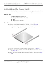
Each Ethernet switch is configured with a pair of adjustable guide rails.
l
Guide rails can be flexibly adjusted from 600 mm to 900 mm, and installed in the cabinet
with a depth from 800 mm to 1200 mm.
l
Adjustable guide rails come preinstalled with square-hole positioning pins. If required,
change square-hole positioning pins to round-hole ones before installing adjustable guide
rails.
NOTE
You can find the round-hole positioning pins in the accessory bag delivered with storage devices.
l
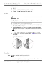
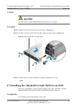
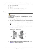
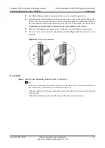
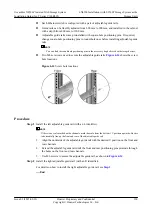
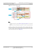
Two M6 screws are used to secure the adjustable guide rails.
shows the screw
hole locations.
Figure 6-14
Screw hole locations
Procedure
Step 1
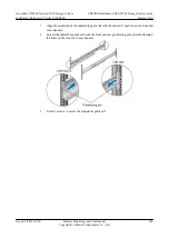
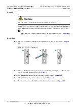
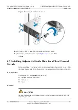
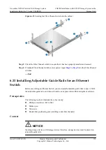
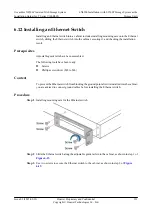
Install the left adjustable guide rail (with an L identifier).
NOTE
If there is no scale marked on the channels, mark the scale from the bottom 1 U position upwards. Be sure
to horizontally line up the front and rear of the adjustable guide rail.
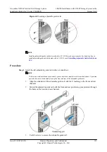
1.
Align the underside of the adjustable guide rail with the desired U position on the front and
rear channels.
2.
Extend the adjustable guide rail until the front and rear positioning pins protrude through
the holes on the front and rear channels.
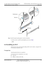
3.
Use M6 screws to secure the adjustable guide rail, as shown in
.
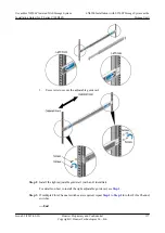
Step 2
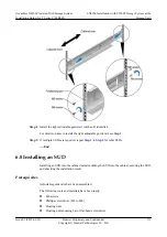
Install the right adjustable guide rail (with an R identifier).
For details on how to install the right adjustable guide rail, see
----End
OceanStor N8500 Clustered NAS Storage System
Installation Guide (for T Series V100R005)
6 N8500 Installation (with S5500T Storage System as the
Storage Unit)
Issue 02 (2015-09-22)
Huawei Proprietary and Confidential
Copyright © Huawei Technologies Co., Ltd.
120

