background image


IPC2702-VF-VP 

Quick Start Guide 

2

 Device Ports and Description 


Issue 10 (2014-02-25) 

Huawei Proprietary and Confidential                                     

Copyright © Huawei Technologies Co., Ltd.   


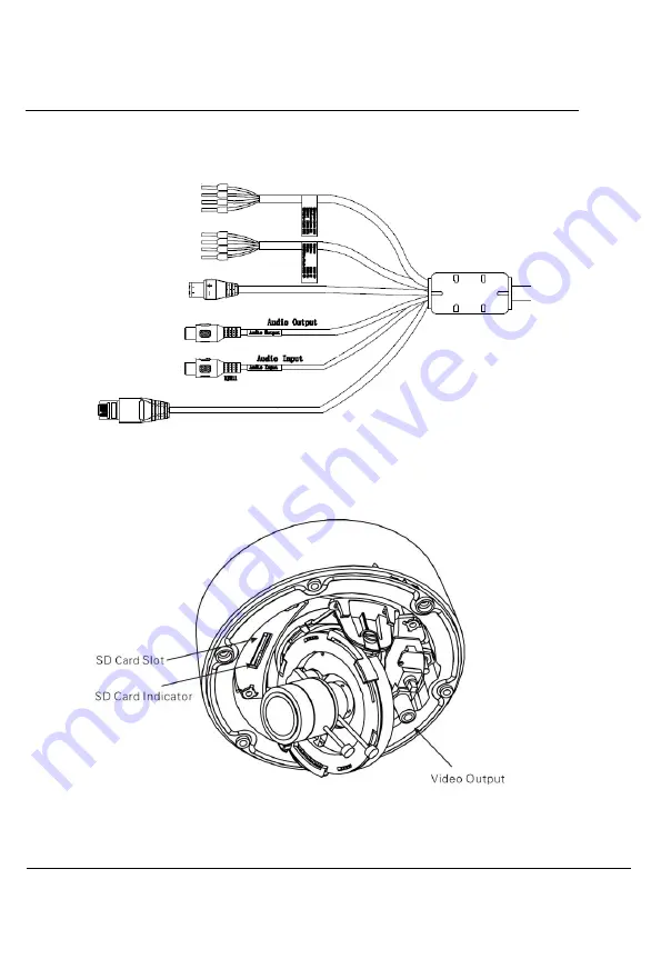
Figure 2-2


Multi-head cable


Figure 2-3 shows the SD card slot, which is described in Table 2-1. 

Figure 2-3


SD slot


Содержание IPC2702-VF-VP

Страница 1: ...IPC2702 VF VP V100R001C03SPC600 Quick Start Guide Issue 10 Date 2014 02 25 HUAWEI TECHNOLOGIES CO LTD ...

Страница 2: ......

Страница 3: ...ei and the customer All or part of the products services and features described in this document may not be within the purchase scope or the usage scope Unless otherwise specified in the contract all statements information and recommendations in this document are provided AS IS without warranties guarantees or representations of any kind either express or implied The information in this document i...

Страница 4: ...uick start for Vandal Dome Network Cameras including the product features hardware installation network access network configuration daily maintenance and troubleshooting This document applies to eSpace IPC2702 VF VP Intended Audience This document is intended for Technical support engineers Maintenance engineers Symbol Conventions The symbols that may be found in this document are defined as foll...

Страница 5: ...uipment damage data loss performance deterioration or unanticipated results NOTICE is used to address practices not related to personal injury Calls attention to important information best practices and tips NOTE is used to address information not related to personal injury equipment damage and environment deterioration Change History Changes between document issues are cumulative The latest docum...

Страница 6: ...nt Modified the suitable model Updates in Issue 07 2013 07 31 This issue is the seventh official release compared to issue 06 Modified Chapter 2 Device Ports and Description Modified description about network indicator 4 1 Login and Logout Modified the caution 4 2 Main Page Layout Modified the web configuration page Updates in Issue 06 2013 05 30 This issue is the sixth official release compared t...

Страница 7: ...d the diagrams of the infrared lamp board and SD card slots 3 2 Installing a Vandal Dome Network Camera Modified the installation procedure Updates in Issue 03 2012 12 30 This issue is the third official release compared to issue 02 Added 1 1 Safety Precautions Added description about lightening protection measures and working high above the ground Updates in Issue 02 2012 09 30 This issue is the ...

Страница 8: ...packing Inspection 4 1 4 Network Plan 5 2 Device Ports and Description 6 3 Hardware Installation 11 3 1 Preparing Installation Tools 11 3 2 Installing a Vandal Dome Network Camera 11 3 2 1 Installation Modes 11 3 2 2 Installing a Dome Camera in Wall Mounted Mode 12 3 2 3 Optional Accessories 17 4 Quick Configuration 19 4 1 Login and Logout 19 4 2 Main Page Layout 20 4 3 Browsing Videos 24 4 4 Sett...

Страница 9: ...area The actual device governs and this document is only for reference The device may be upgraded without prior notice For the latest programs and supplementary documentation contact Huawei customer service center If any problems occur during use contact the supplier or customer service center Any loss caused by improper operations is born by the buyer Basic Precautions Install the device in stric...

Страница 10: ...evice during delivery from or sending back to the manufacture for repair is out of the warranties Never install the device upside down Hold the device with careful Never tightly press any structural parts otherwise mechanical breakdown may occur Never dissemble the device to repair it The device must be checked and repaired by professional maintenance personnel Never scratch or abrade the device s...

Страница 11: ...urce or ignition source such as an electric heater or lighted candle Never install or use the device in places where flammable or explosive materials are saved or in use Deploy surge protection devices if the device is installed outside When working high above the ground take security measures such as wearing helmets and safety belts and choosing secure elevating apparatus Personnel Precautions Th...

Страница 12: ...evice and accessories based on the packing list Verify that materials such as the host cables matching documentation and CD ROM are complete and in perfect condition If there is any material damaged or lost contact the local dealer Packing list is described in Table 1 2 Table 1 2 Packing list No Item Quantity 1 Quick start 1 2 Hard copies 1 3 Certificate 1 4 Warranty card 1 5 T15 screwdriver 1 6 J...

Страница 13: ... Guide 1 Installation Preparation Issue 10 2014 02 25 Huawei Proprietary and Confidential Copyright Huawei Technologies Co Ltd 5 1 4 Network Plan Figure 1 1 shows the typical network diagram Figure 1 1 Technical network diagram ...

Страница 14: ...l Copyright Huawei Technologies Co Ltd 6 2 Device Ports and Description Product Appearance Figure 2 1 shows the appearance of a Vandal Dome Network Camera Figure 2 1 Vandal Dome Network Camera Hardware Connection Figure 2 2 shows the multi head cable used by a Vandal Dome Network Camera which is described in Table 2 1 ...

Страница 15: ...Device Ports and Description Issue 10 2014 02 25 Huawei Proprietary and Confidential Copyright Huawei Technologies Co Ltd 7 Figure 2 2 Multi head cable Figure 2 3 shows the SD card slot which is described in Table 2 1 Figure 2 3 SD slot ...

Страница 16: ...ate power supply indicator red on VIDEO OUT port Sends analog video signals You can connect the camera to a TV monitor through this port to view analog videos Alarm input IN0 COM0 Alarm input port NOTE The voltage and current of the external power supply cannot exceed DC 12 V and 300 mA Alarm output COM1 OUT1 Alarm output port RS485 port TX TX RX and RX Connects an external Pan Tilt Zoom PTZ SD ca...

Страница 17: ... indicator on and the green indicator is flashing which in the adjacent position Alarm input output device connection Vandal dome network camera can connect 1 alarm input and 1 digital output Alarm input connection is shown in Figure 2 4 Figure 2 4 Alarm input connection In alarm configuration web If the Alarm level is set to Low the camera will not alarm when the alarm input terminal signal is lo...

Страница 18: ... AC external power supply an external relay is needed or it will be in risk of electric shock If alarm output is the switch no voltage the external power supply is needed when the camera connect to the alarm If connect to the external DC power supply it must be in DC 12V voltage 300mA limit range If connect to the AC external power supply an external relay is needed if not it will damage the equip...

Страница 19: ...on tools Tool Description Phillips screwdriver Claw hammer Hammer drill Level ruler 3 2 Installing a Vandal Dome Network Camera 3 2 1 Installation Modes A Vandal Dome Network Camera supports the wall mounted column mounted suspension and corner mounted installation modes For details see the Installation Guide The following describes how to install a Vandal Dome Network Camera in wall mounted mode ...

Страница 20: ...e plum screws on the upper case and remove the upper case as shown in Figure 3 2 Figure 3 1 T15 screw driver Figure 3 2 Loosing screws Step 2 Determine the installation location and use the Φ4 5 hammer driller to drill three holes whose depth is more than 30 mm on the wall Step 3 Insert one white inflatable colloidal particle into the three holes respectively Step 4 Remove the three black screws o...

Страница 21: ...fidential Copyright Huawei Technologies Co Ltd 13 Figure 3 3 Direct installation Step 7 Install the upper case End Lower Case Mounting Installation Step 1 Use the T15 screwdriver to loosen the three plum screws on the upper case and remove the upper case as shown in Figure 3 4 Figure 3 4 Loosing screws ...

Страница 22: ...ll three holes whose depth is more than 30 mm on the wall 4 Insert one white inflatable colloidal particle into the three holes respectively 5 Use the three black 70 mm self tapping screws from the PE accessory bag to secure the lower case on the wall as shown in Figure 3 5 Figure 3 5 Mounting the lower case Step 3 Attach the bottom cover to the lower case 1 Insert the bottom cover into the lower ...

Страница 23: ...tial Copyright Huawei Technologies Co Ltd 15 Figure 3 6 Attaching the bottom cover to the lower case Step 4 Remove the liner in the direction shown in Figure 3 7 Figure 3 7 Removing the liner Step 5 Adjust the focus 1 Adjust the lens angle and fix the focusing lever 2 Install the liner and lock it into place ...

Страница 24: ...using lever is locked If you want to adjust the focus release the focusing lever and then adjust the lens angle and focus as shown in Figure 3 8 Figure 3 8 Adjusting the lens angle and focus Step 6 Install the upper case Step 7 Use the T15 screwdriver to tighten the three plum screw to ensure that no noticeable gap between the upper and lower cases as shown in Figure 3 9 ...

Страница 25: ...Co Ltd 17 Figure 3 9 Installing the upper case End 3 2 3 Optional Accessories Table 3 2 lists optional accessories that may be required during installation Table 3 2 Optional accessories Accessory Picture Description Adapter An adapter can replace the camera lower case and is applicable to ceiling mounted installation Wall mounted bracket N A ...

Страница 26: ...5 Huawei Proprietary and Confidential Copyright Huawei Technologies Co Ltd 18 Power box A power box is applicable to wall or corner mounted installation Cables can be led out through the side or bottom hole Column mounted bracket N A Corner mounted bracket Suspension bracket ...

Страница 27: ...in and Logout You must use Internet Explorer 7 Internet Explorer 8 and Internet Explorer 9 to access the web management system otherwise some functions may be unavailable Login Step 1 Open Internet Explorer enter the IP address of the IP camera default value 192 168 0 120 in the address box and press Enter The login page is displayed as shown in Figure 4 1 Figure 4 1 Login page ...

Страница 28: ...your account is locked You must wait for five minutes to enter the login information Only a user with the Privilege Manage permission can unlock a locked account You can change the system display language on the login page Step 3 Click Login The main page is displayed End Logout To log out of the system click Sign out in the upper right corner of the main page The login page is displayed after you...

Страница 29: ...area You can also set sensor parameters 2 Menu area You can choose a menu to see device parameters including the device information audio and video streams alarm setting and privacy mask function 3 Video Parameter Video parameters such as the I frame interval bit rate type bit rate and quality are displayed 4 Video Control You can perform the following operations in this area Switch between camera...

Страница 30: ...north Enable or disable 3D positioning Set the PTZ timer NOTE The PTZ timer functions as a time trigger When it is activated the PTZ rotates according to preset positions or tracks as scheduled The timer uses the time set in the IP camera Ensure that the time is correct All PTZ functions are only available to High Speed Network Dome and device connected to an external PTZ 7 Sign Out You can click ...

Страница 31: ...t corner of the main page The Modify Password dialog box is displayed as shown in Figure 4 3 Figure 4 3 Modify Password dialog box Step 2 Enter the old password new password and confirmation password Step 3 Click OK If the message Modify Password Success Please login system again is displayed the password is successfully changed If the password fails to be changed the cause is displayed For exampl...

Страница 32: ...rations when you log in to the web management system for the first time Step 1 Open Internet Explorer Choose Tools Internet Options Security Trusted sites Sites In the displayed dialog box click Add as shown in Figure 4 4 Figure 4 4 Adding a trusted site Step 2 In Internet Explorer choose Tools Internet Options Security Internet Customer level and set Download unsigned ActiveX controls and Initial...

Страница 33: ... ActiveX controls and plug ins Step 3 Download and install the player control as prompted If the repair tips displayed when installing the control please ignore the prompt and continue the installation the login page will displayed when the control is loaded End Description To browse real time videos click Live Video The Live Video page is displayed as shown in Figure 4 6 ...

Страница 34: ...Video page 4 4 Setting Local Network Parameters Description Local network parameters include IP protocol IP address Subnet mask Default gateway Dynamic Host Configuration Protocol DHCP Preferred Domain Name System DNS server Alternate DNS server MTU Procedure Step 1 Choose Device Configuration Local Network The Local Network page is displayed as shown in Figure 4 7 ...

Страница 35: ...awei Technologies Co Ltd 27 Figure 4 7 Local Network page Step 2 Set the parameters according to Table 4 2 Table 4 2 Local network parameters Parameter Description Setting IP Protocol IPv4 is the IP protocol that uses an address length of 32 bits Setting method Select a value from the drop down list box Default value IPv4 ...

Страница 36: ...ss Device IP address that can be set as required Setting method Enter a value manually Default value 192 168 0 120 Subnet Mask Subnet mask of the network adapter Setting method Enter a value manually Default value 255 255 255 0 Default Gateway This parameter must be set if the client accesses the device through a gateway Setting method Enter a value manually Default value 192 168 0 1 Preferred DNS...

Страница 37: ... range from 800 to 1500 the default value is 1380 Please do not change it arbitrarily Step 3 Click OK If the message Network Parameter Updated is displayed click OK The system saves the settings The message Set network parameters success Please login system again is displayed Use the new IP address to log in to the web management system If the message Invalid IP Address Invalid Subnet Mask Invalid...

Страница 38: ...te not recommended The web management system cannot be accessed The network is disconnected Connect the PC directly to the camera and verify that the web management system can be accessed Run the ping command to verify that the camera is reachable The IP address is used by another device Connect the PC directly to the camera and configure the IP address of the camera The IP addresses of the PC and...

Страница 39: ...che proceed as follows Internet Explorer 8 is used as an example 1 Open Internet Explorer 2 Choose Tools Internet Options General 3 Click Delete The Delete Browsing History dialog box is displayed 4 Select all check boxes 5 Click Delete Log in to the web management system again The IP camera cannot be upgraded The network is disconnected or the network settings are incorrect Connect the PC directl...

Страница 40: ...ion Products Parts Hazardous Substances Pb Hg Cd Cr6 PBB PBDE Mechanical part Board circuit module Cable connector Auxiliary equipment Indicates that the concentration of the hazardous substance contained in all the homogeneous materials of this part is below the limit requirement of the SJ T 11363 2006 standard Indicates that the concentration of the hazardous substance contained in all the homog...

Отзывы: