background image

eAN3810A   
Hardware Installation Guide 

1 eAN3810A Hardware Installation Guide 


Issue 01 (2017-04-30) 

Huawei Proprietary and Confidential                                     

Copyright © Huawei Technologies Co., Ltd. 

29 


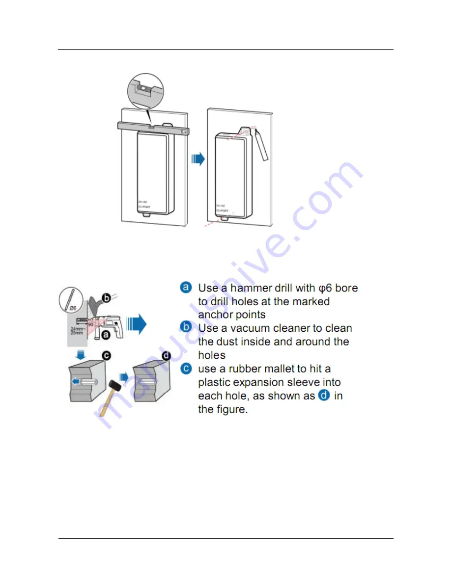
Figure 1-26


Marking anchor points 


Step 2


Drill holes and install expansion bolts. 

Figure 1-27


Drill holes and install expansion bolts 


Step 3


Install the PSE 

Содержание eAN3810A

Страница 1: ...eAN3810A V100R001C00 Hardware Installation Guide Issue 01 Date 2017 04 30 HUAWEI TECHNOLOGIES CO LTD ...

Страница 2: ...e customer All or part of the products services and features described in this document may not be within the purchase scope or the usage scope Unless otherwise specified in the contract all statements information and recommendations in this document are provided AS IS without warranties guarantees or representations of any kind either express or implied The information in this document is subject...

Страница 3: ...eAir solution The following table lists the product name and product version related to the 3810 series AirNode Product Name Product Version eAN3810A V100R001C00 Intended Audience This document is intended for installation engineers Organization 1 1 Installation Preparations Before starting the installation you must obtain the required reference documents tools and instruments and familiarize your...

Страница 4: ...stalling the auxiliary devices 1 9 Installing Cables This section describes the procedures for installing eAN3810A cables and auxiliary devices cables 1 10 Checking Hardware Installation eAN3810A hardware installation checking includes hardware and cable installation checking 1 11 Power On Check on the eAN3810A This section describes the procedure for performing a power on check on the eAN3810A 1 ...

Страница 5: ...o M6 Flat head screwdriver M3 to M6 Rubber mallet COAX crimping tool Wire stripper Power cable crimping tool RJ45 crimping tool Diagonal plier Utility knife Level Network cable tester Adjustable wrench size 32 mm 1 26 in Torque wrench Size 16 mm 0 63 in and 22 mm 0 87 in Combination wrench Size 16 mm 0 63 in and 22 mm 0 87 in Torque screwdriver 3mm or 5mm M3 to M6 M3 to M6 Marker diameter 10 mm 0 ...

Страница 6: ...ation personnel depends on the engineering schedule and installation environment Generally two to three persons are required Generally only three to five onsite personnel are necessary 1 2 Information About the Installation This section describes the information that you must be familiar with before installing a eAN3810A including the eAN3810A hardward infomation installation scenarios installatio...

Страница 7: ...ons and Restrictions The eAN3810A can be installed on a wall or pole Installation scenarios must meet heat dissipation and waterproofing requirements of the eAN3810A Installation on a Pole Figure 1 1 shows the diameter of a pole for installing an eAN3810A Figure 1 1 Diameter of a pole for installing a eAN3810A The diameter of a pole for installing a eAN3810A ranges from 48 mm 1 89 in to 114 mm 4 4...

Страница 8: ...A eAN3810A installed on a pole Installation on a Wall The wall for installing eAN3810A must meet the following requirements The wall can bear a load at least four times the weight of a eAN3810A The screws must be tightened with a torque of 30 N m This ensures the screws work properly and the wall remains intact without cracks in it Figure 1 3 shows the eAN3810A installed on a pole ...

Страница 9: ...eration and maintenance O M Based on the engineering practice the recommendation for the installation clearance is provided The recommended clearances are for customers ensuring normal running and providing appropriate space for O M If installation space is sufficient leave the recommended clearances after installing equipment The minimum clearance ensures normal operation and heat dissipation but...

Страница 10: ...e Installation Guide Issue 01 2017 04 30 Huawei Proprietary and Confidential Copyright Huawei Technologies Co Ltd 8 Figure 1 4 Clearances for installing a eAN3810A Installation Spacing Between eAN3810A Figure 1 5 lists the horizonta spacing between eAN3810A ...

Страница 11: ... 1 eAN3810A Hardware Installation Guide Issue 01 2017 04 30 Huawei Proprietary and Confidential Copyright Huawei Technologies Co Ltd 9 Figure 1 5 Clearances for installing a eAN3810A Figure 1 6 lists the vertical spacing between eAN3810A ...

Страница 12: ...g environment specifications for the eAN3810A Running Environment Specifications Table 1 2 shows the environment specifications for the eAN3810A Table 1 2 Environment specifications of eAN3810A Item Specifications Operating temperature 40ºC to 45ºC with solar radiation 40ºC to 50ºC without solar radiation NOTE At 40ºC to 20ºC the AirNode can start up but its performance cannot meet requirements At...

Страница 13: ...lled in an enclosed cabinet without a cooling system The eAN3810A cannot be installed in an enclosed camouflage box The eAN3810A cannot be installed in an enclosed equipment room without a cooling system If the eAN3810A is inappropriately installed heat dissipation of the eAN3810A deteriorates and the eAN3810A may not work properly as shown in Figure 1 7 Figure 1 7 Inappropriately installed eAN381...

Страница 14: ...ded and intact Context When transporting moving or installing the equipment components or parts you must Prevent them from colliding with doors walls shelves or other objects Wear clean gloves and avoid touching the equipment components or parts with bare hands sweat soaked gloves or dirty gloves Power on an eAN3810A within 24 hours after unpacking it If you power off an eAN3810A for maintenance r...

Страница 15: ...e Step 3 Check the type and quantity of the equipment in the boxes according to the packing list If Then The type and number are consistent with the packing list on each packing list Sign the Packing List with the operator There is any shortage wrong delivery or damaged equipment Report the problems and causes to the local Huawei office To protect the equipment from damage keep the unpacked equipm...

Страница 16: ...810A installation process 1 5 Obtaining the ESN Before installing the eAN3810A record its electronic serial number ESN for future use during commissioning Context The ESN uniquely identifies a device and is required during commissioning Procedure Step 1 Remove the backup ESN label from the surface of the eAN3810A as shown in Figure 1 10 Before removing the backup SN label photograph it ...

Страница 17: ...ssioning personnel End 1 6 Optional Installing a Micro SD Card This section describes how to install a micro SD card in the eAN3810A Prerequisites Software and configuration data files need to be prepared for the micro SD card to be installed For detailed operations see eAN3810A Deployment Guide Procedure Step 1 Wear ESD gloves Step 2 Use an M6 inner hexagon screwdriver to loosen a screw on the ca...

Страница 18: ...g the eAN3810A This section describes the eAN3810A installation process 1 7 1 Installing eAN3810A on a Pole This section describes the procedure and precautions for installing an eAN3810A on a pole Context Do not stand an eAN3810A upright because the RF ports cannot support the weight of the eAN3810A Place a foam pad or cardboard under an eAN3810A to protect the eAN3810A housing from damage during...

Страница 19: ...l the mounting kit as shown in Figure 1 13 Figure 1 13 Installing the eAN3810A mounting kit 1 Determine a position for installing the eAN3810A Then place the separate mounting kit onto the pole thread the hose clamp through the mounting kit and encircle the pole with the hose clamp as shown by illustrations a b and c in Figure 1 13 2 Use an M6 inner hexagon screwdriver to tighten the bolt on each ...

Страница 20: ...n Figure 1 14 2 Use the M6 inner hexagon screwdriver to tighten the screw on the top of the attachment plate to 5 N m 44 25 lbf in as shown by illustration c in Figure 1 14 End 1 7 2 Installing eAN3810A on a Wall This section describes the procedure and precautions for installing an eAN3810A on a wall Context The wall for installing eAN3810As must meet the following requirements The wall must be a...

Страница 21: ...A housing from damage during the installation Procedure Step 1 Determine a position for installing the eAN3810A on a wall use a level to verify that the marking off template is placed horizontally and then use a marker to mark anchor points as shown in Figure 1 15 Figure 1 15 Marking anchor points 1 Level 2 Tapped hole 3 Marker It is recommended that the separate mounting kit be 1200 mm 47 24 in t...

Страница 22: ...illing holes 2 Use a vacuum cleaner to clear the dust out from inside and around the holes and measure the distances between holes If any of the holes is beyond the acceptable range mark a new anchor point and drill a new hole 3 Tighten the expansion bolts slightly and place each expansion bolt vertically into each hole 4 Use a rubber mallet to pound each expansion bolt until the corresponding exp...

Страница 23: ...Nut 2 Spring washer 3 Flat washer Step 4 Hold the eAN3810A hang the two dowels on the top of the eAN3810A attachment plate onto the separate mounting kit and push the eAN3810A until it snaps into place as shown by illustrations a and b in Figure 1 18 Step 5 Use the M6 inner hexagon screwdriver to tighten the screw on the top of the separate attachment plate to 5 N m 61 96 lbf in as shown by illust...

Страница 24: ...re and precautions for installing the auxiliary devices 1 8 1 Optional Installing a Dock This section describes the procedure and precautions for installing a dock Installing a Dock on a Pole This section describes the procedure and precautions for installing the Dock on a pole Procedure Step 1 Use an M4 inner hexagon screwdriver to remove the Dock integrated mounting bracket install the Dock sepa...

Страница 25: ...wei Proprietary and Confidential Copyright Huawei Technologies Co Ltd 23 Figure 1 19 Replacing the Dock mounting bracket Step 2 Route two hose clamps through the up and down mounting holes on the Dock separate mounting bracket but do not route the steel belts through the locks as shown in Figure 1 20 ...

Страница 26: ...mps through the Dock separate mounting bracket Step 3 Put the Dock in the installation position route two hose clamps through the pole and the steel belts through the locking connectors partially tighten the screws and use an M6 inner hexagon torque screwdriver to tighten the screws to 5 N m 44 25 lbf in as shown in Figure 1 21 Ensure that your body is close to the module when tightening hose clam...

Страница 27: ...td 25 Figure 1 21 Tightening hose clamps End Installing a Dock on a Wall This section describes the procedure and precautions for installing the Dock on a wall Procedure Step 1 Place the Dock separate mounting bracket against the wall use a level to verify that the mounting bracket is horizontally placed and use a marker to mark anchor points as shown in Figure 1 22 ...

Страница 28: ...nologies Co Ltd 26 Figure 1 22 Marking anchor points 1 Level 2 Mounting hole 3 Marker 4 Dock separate mounting bracket Step 2 Drill holes at the anchor points and install expansion bolt assemblies as shown in Figure 1 23 Figure 1 23 Drilling holes and installing expansion bolt assemblies 1 M6x60 bolt 2 Nut 3 Spring washer 4 Flat washer 5 Expansion tube ...

Страница 29: ...ing is too wide or too narrow drill holes again 3 Tighten each expansion bolt slightly and place them perpendicularly into each hole 4 Hit each expansion bolt using a rubber mallet to enable the expansion tube to enter the hole completely 5 Remove the M6x60 bolt nut spring washer and flat washer from each expansion bolt assembly in sequence Step 3 Use an M4 inner hexagon screwdriver to remove the ...

Страница 30: ...Figure 1 25 Fitting the Dock onto the wall 1 Bolt 2 Flat washer 3 Spring washer 4 Nut End 1 8 2 Optional Installing the PSE This section describes the procedure and precautions for installing the PSE on a wall Context The PSE can be installed only on an indoor wall Procedure Step 1 Place the PSE against the wall level it in the installation position and mark anchor points ...

Страница 31: ...lation Guide Issue 01 2017 04 30 Huawei Proprietary and Confidential Copyright Huawei Technologies Co Ltd 29 Figure 1 26 Marking anchor points Step 2 Drill holes and install expansion bolts Figure 1 27 Drill holes and install expansion bolts Step 3 Install the PSE ...

Страница 32: ...s Bending radius requirements The bending radius of a 7 8 feeder must be greater than 250 mm 9 84 in and the bending radius of a 5 4 feeder must be greater than 380 mm 14 96 in The bending radius of a 1 4 jumper must be greater than 35 mm 1 38 in The bending radius of a super flexible 1 2 jumper must be greater than 50 mm 1 97 in and the bending radius of an ordinary 1 2 jumper must be greater tha...

Страница 33: ...ore routing them into the room Ensure that the radiuses of the drip loops are greater than or equal to the minimum bending radiuses of the cables When routing a cable into the room ensure that a person is assisting you in the room Apply waterproof treatment to the feeder window Outdoor Cabling Requirements Protect outdoor cables against potential damage For example thread the cables through tubes ...

Страница 34: ...nd signal cables must be installed separately A certain distance must be reserved between them to prevent interference from each other Switches or fuses must not be installed on the PGND cables Other devices must not be used for electrical connections of the PGND cables All the metal parts in the housing of the equipment must be reliably connected to the ground terminal 1 9 2 Cable Connections Thi...

Страница 35: ...rocedure Step 1 Prepare a eAN3810A PGND cable 1 Cut the cable to a length suitable for the actual cable route 2 Add OT terminals to both ends of the cable Step 2 Install the eAN3810A PGND cable Connect one end of the PGND cable with an M6 OT terminal to the ground terminal at the eAN3810A bottom and the other end of the cable with an M8 OT terminal to the external ground bar as shown in Figure 1 3...

Страница 36: ...low the same procedure when installing a Dock PGND cable End 1 9 4 Installing a RF Jumper This section describes the procedure for installing an RF jumper Procedure Step 1 Remove the dustproof cap from the ANT port to be used on the eAN3810A Step 2 Connect the type N male connector at one end of the eAN3810A RF jumper to the ANT port at the bottom of the eAN3810A in sequence and use a torque wrenc...

Страница 37: ...ei Technologies Co Ltd 35 Figure 1 32 Installing an RF jumper Step 3 Connect the other end of the eAN3810A RF jumper to the external antenna system Step 4 Waterproof the connector of the RF jumper by Waterproof tape as shown in Figure2 Figure 1 33 Waterproof the connector of the RF jumper by waterproof tape 1 PVC insulation tape 2 Waterproof tape ...

Страница 38: ... 5 Check the dustproof caps on antenna connectors In outdoor scenarios dustproof caps must be waterproofed as shown in Figure3 Do not remove dustproof caps from vacant antenna connectors Figure 1 34 Waterproofing a dustproof cap 1 Dustproof cap 2 PVC insulation tape 3 Waterproof tape 1 Verify that dustproof caps are not removed 2 Wrap one layer of PVC insulation tape on each connector from bottom ...

Страница 39: ...gory 5e enhanced or higher In addition its cross sectional area must be 24 AWG or larger and frame spread rating must be CM or higher Both the cable and the RJ45 connectors are delivered and they must be assembled onsite You need to use a network cable tester to test the Ethernet cable connection With the internal PoE module providing power the maximum length of an Ethernet cable is 100 m Procedur...

Страница 40: ... the eAN3810A panel 2 Ethernet cable Step 3 Connect the RJ45 connector at the other end of the Ethernet cable to auxiliary devices port End Follow up Procedure 1 Route the cable and then use a cable tie to bind the cable 2 Label the installed cable 1 9 6 Optional Installing the PSE Cable This section describes the procedure and precautions for installing the PSE cables Figure 1 36 shows the cable ...

Страница 41: ...00 m 1 9 7 Optional Installing the Dock Ethernet Cable This section describes procedure and precautions for installing a Dock Ethernet cable Context The Ethernet cable must be of Category 5e enhanced or higher In addition its cross sectional area must be 24 AWG or larger and frame spread rating must be CM or higher Ethernet cables are not delivered and they must be prepared onsite You need to use ...

Страница 42: ... 1 Ethernet cable between Dock and external transmission device 2 Ethernet cable between eAN3810A and Dock 1 Connect one end of the assembled Ethernet cable to the WAN port in the cabling cavity of the Dock and the other end to the external transmission device 2 Connect the other end of the Ethernet cable which is connected to the PoE port on the eAN3810A to the LAN0 port in the cabling cavity of ...

Страница 43: ...ower device Dock cascading power cable L Brown Cord end terminal 1 5 mm2 Cord end terminal 1 5 mm2 N Blue Cord end terminal 1 5 mm2 Cord end terminal 1 5 mm2 PE Yellow and green Cord end terminal 1 5 mm2 Cord end terminal 1 5 mm2 The color and structure of the power cables differ in different countries and regions The power cables purchased locally must conform to the local standards Procedure Ste...

Страница 44: ...port on the left side and tighten the wiring posts Connect the other end to external devices 3 Optional Install Dock cascading power cables Use a flat head screwdriver to loosen the right ports on the L N and PE wiring posts inside one Dock Connect one end of each cable to the corresponding port on the right side and tighten the wiring posts Connect the other end of cables to corresponding ports o...

Страница 45: ...sue 01 2017 04 30 Huawei Proprietary and Confidential Copyright Huawei Technologies Co Ltd 43 Figure 1 38 Installing power cables The protective cover of the power supply terminal is automatically secured After the procedure is complete tap the protective cover to restore it End ...

Страница 46: ...vity and the cover plate of the cabling cavity is securely installed In addition vacant RF ports are covered with dustproof caps and the caps are tightened 5 Labels are correct legible and complete at both ends of each cable feeder and jumper Table 1 5 lists the check items of the signal cable connection Table 1 5 Checklist for the signal cable connection No Item 1 The connectors of the signal cab...

Страница 47: ...ering design 4 There are no connectors or joints on each PGND cable None of PGND cables can be short circuited or reversely connected In addition these cables are not damaged or broken 5 PGND cables are separately bound from other cables 6 The protection grounding of the eAN3810A and the surge protection grounding of the building share one group of ground conductors 1 11 Power On Check on the eAN3...

Страница 48: ...hecking the Indicator Status Table 1 7 Checking the indicator status If then RUN Steady white The eAN3810A is running correctly ETH Blinking white WIFI Off LINK Off During the eAN3810A startup there is no need to observe the indicator status During a start the eAN3810A reads and writes the flash and therefore the indicators blinking quickly may blink irregularly for 1 2 seconds which does not affe...

Страница 49: ...e xx eAN_1 xx floor xx building xx mansion Note The ESN collection template is essential to the engineering stage and subsequent maintenance especially when multiple devices are installed at a short distance This is because the template defines the radio network to access Please maintain this template with caution 1 12 2 Antenna Installation This section describes the reference documents for insta...

Страница 50: ...dware Installation Guide 1 eAN3810A Hardware Installation Guide Issue 01 2017 04 30 Huawei Proprietary and Confidential Copyright Huawei Technologies Co Ltd 48 Related Document Description Installation Guide system ...

Отзывы: