
HLogic Security Technology Co., Ltd
www. hstfire .com
Document Ref: M7285-01
Issue:1.0
07/2016
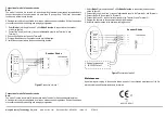
Connection of mode 1 of sounder strobe
Note:
The mode 1 is used in low currents in 2-wires loop without external power supply, recommended to
connect the number of sounder strobe not more than 15 pcs per loop. The mode1 has sounder
function only without strobe function.
All wiring must conform to applicable local codes, ordinances, and regulations. Written the address
of sounder strobe before mounting and wiring by programmer.
1. Select
Mode 1
(set the pin1 and pin2 of the
Mode Selection
to connected on the sounder
strobe) as figure 4.
2. Connect the loop (+) and loop (–) wires of addressable panel to the Terminal L+ and
Terminal L-.
3. Connect the Earth wire of panel to Terminal E.
4. Program the address on the sounder strobe per job drawings.
5. Install the sounder strobe in the desired mounting location.
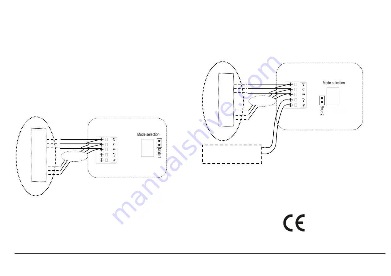
Connection of mode 2 of sounder strobe
Note:
The mode 2 is used in normal with sounder and strobe function for 4-wires addressable system.
All wiring must conform to applicable local codes, ordinances, and regulations. Written the address
of sounder strobe before mounting and wiring by programmer.
1. Select
Mode 2
(set the pin2 and pin3 of the
Mode Selection
to connected) on the sounder
strobe as figure 5.
2. Connect the loop (+) and loop (–) wires of addressable panel to the Terminal L+ and Terminal L-.
3. Connect the Earth wire of panel to Terminal E.
4. Connect the V+and V– wires of external supply to the Terminal V+ and Terminal V-.
5. Program the address on the sounder strobe per job drawings.
6. Install the sounder strobe in the desired mounting location.
Figure5
Connection of mode 2
Maintenance
Apart from regular testing of the sounder strobe, as part of the scheduled maintenance of the fire
alarm system, no additional maintenance is required.
Figure4
Connection of mode 1
Sounder Strobe
Fir
e
ala
rm
co
ntr
ol
pa
ne
l
Loop
Out+
Out-
Earth
In+
In-
Earth
Next devices
Sounder Strobe
Fir
e
ala
rm
co
ntr
ol
pa
ne
l
Loop
Out+
Out-
Earth
In+
In-
Earth
Next devices
V+
V-
External power supply
24-32VDC Output
HST
17
A-201 CPR 2017
17


