background image

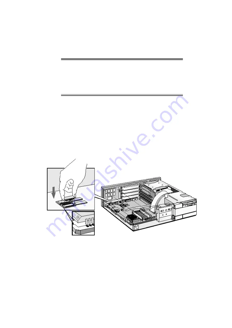
INSTALLING A VIDEO MEMORY UPGRADE

Your PC is supplied with 1 MB of video memory on the system board. If you want better
performance, higher resolutions or more colors, you can install a pair of video memory
modules to increase your available video memory to 2 MB. Detailed information about
available video resolutions is given in chapter 5, Technical Information.

CAUTION:

Static electricity can damage electronic
components. Turn all equipment OFF. Don’t let
your clothes touch the accessory. To equalize
the static electricity, rest the accessory bag on
top of the power supply while you are removing
the accessory from the bag. Handle the
accessory as little as possible and with care.

Installing Video Memory Modules

To install a pair of video memory modules on the system board, follow this procedure:

1

Disconnect the power supply cord and any connection to a telecommunications network.

2

Remove the computer’s cover and power supply.

3

Align the video memory module directly over the socket taking care to align the dot on the
module with the corner notch on the socket as illustrated in the diagram. 

Firmly press the

memory module 

completely into the connector. Video memory modules must be installed

in pairs.

4

Install any other accessories before replacing the cover and power supply. Reconnect all
cables and power cords.

Содержание Vectra XM 5Series

Страница 1: ...HP Vectra XM 5 xx Series 4 PCs User s Guide ...

Страница 2: ...24 REPLACING THE POWER SUPPLY AFTER INSTALLING ACCESSORIES 26 INSTALLING MEMORY 26 INSTALLING AN OPTIONAL CACHE MEMORY MODULE 28 INSTALLING A VIDEO MEMORY UPGRADE 29 INSTALLING ACCESSORY BOARDS 30 CONFIGURING ACCESSORY BOARDS WITH PLUG AND PLAY 30 CONFIGURING NON PLUG AND PLAY ISA ACCESSORY BOARDS 30 INSTALLING THE BOARD 31 INSTALLING A BNC COAX ADAPTER 34 INSTALLING MASS STORAGE DEVICES 36 CONFIG...

Страница 3: ...LVING PROBLEMS 69 HP SUMMARY SCREEN 69 IF YOUR PC DOES NOT START PROPERLY 69 DISPLAY IS BLANK AND THERE ARE NO ERROR MESSAGES 69 IF YOU ARE UNABLE TO CHANGE ANY VALUES IN SETUP 70 IF A POST ERROR MESSAGE IS DISPLAYED 71 IF YOU CANNOT TURN OFF YOUR PC 72 IF YOUR PC HAS A HARDWARE PROBLEM 72 DISPLAY DOES NOT WORK PROPERLY 72 IF YOUR KEYBOARD DOES NOT WORK 74 IF YOUR MOUSE DOES NOT WORK 74 IF YOUR PR...

Страница 4: ...P FORUM ON COMPUSERVE 90 HP FORUM ON AMERICA ONLINE 91 HP BBS LIBRARY 91 INTERNET FTP LIBRARY SERVICE 92 ACCESS HP WORLD WIDE WEB SITE 92 HP FAXBACK ON DEMAND HP FIRST 92 HP AUDIO TIPS USA ONLY HP AUTOMATED SUPPORT DIRECTORY 92 ORDERING DRIVERS AND BIOS ON DISKETTE XE DRIVERS XE BIOS 93 HP SUPPORT SERVICES 93 HEWLETT PACKARD TELEPHONE SUPPORT 94 LIFELINE TELEPHONE SUPPORT 95 HP NETWORK PHONE IN SU...

Страница 5: ...REGULATORY INFORMATION AND WARRANTY 102 REGULATORY INFORMATION 102 FCC FOR USA ONLY 102 HP HARDWARE WARRANTY 104 HP SOFTWARE PRODUCT LICENSE AGREEMENT AND SOFTWARE PRODUCT LIMITED WARRANTY 106 ...

Страница 6: ... Standard Architecture slot one 16 bit ISA short slot 16 cm 6 3 inch maximum length one combination ISA or PCI slot BIOS stored in Flash ROM BIOS support for ISA Plug and Play pre installed operating system software on some models DMI compliant designed for Windows 95 Vectra Ergonomic Power Solution Windows 95 soft power down using the mouse and keyboard power on Energy Star compliant power manage...

Страница 7: ... components the computer and power cord the display and its cables the keyboard and mouse the manuals On some models the operating system software drivers and HP User Tools are preloaded on the hard disk WARNING If you have any doubt that you can lift the PC or display safely do not try to move it without help Computer Typical Display Computer Power Cord Mouse Keyboard Display Power Cord Manuals ...

Страница 8: ...on top of the computer If you have a large display place it next to the computer Refer to the display s manual for information about the display Installation Tools No tools are required to set up your PC However if you plan to install a disk drive or an accessory board in your PC you will need a flat blade screwdriver For further information about installing accessories refer to chapter 3 How to I...

Страница 9: ...E MOUSE KEYBOARD AND DISPLAY 1 Connect the mouse keyboard and display to the back of the computer The connectors are shaped to go in one way only 2 Tighten the display cable attachment screws Mouse Keyboard Display ...

Страница 10: ...able to the RJ 45 UTP Unshielded Twisted Pair LAN connector To configure your network connection refer to Configuring Your Network Connection chapter 3 NOTE If you need a BNC Coax connector to connect to the network you can install an optional BNC coax adapter order HP D3979A Refer to Installing a BNC Coax Adapter chapter 2 ...

Страница 11: ...mputer and tighten the attachment screws Use the connector labeled Parallel 25 pin parallel connector for a parallel device Serial A 9 pin serial connector for a serial device Serial B 9 pin serial connector for a second serial device Parallel Connector Serial Connector ...

Страница 12: ... grounded outlet Display Power Cord Computer Power Cord Grounded Outlet WARNING For your safety always connect the equipment to a grounded wall outlet Always use a power cord with a properly grounded plug such as the one provided with this equipment or one in compliance with your national regulations This PC is disconnected from the power by removing the power cord from the power outlet This means...

Страница 13: ... are away from the PC for a short period of time Your applications will remain active You unlock the PC by entering a password see Setting a User Password in chapter 3 Network Activity Light This light glows flickers when your PC is accessing the network Hard Disk Activity Light This light glows flickers when your hard disk drive is being accessed The hard disk activity light only works if you hav...

Страница 14: ...5 The Application Key The Application key specific to Windows 95 lets you access all the same functions as the right mouse button Use it to copy and move files to access shortcut menus and to get Help information The Application key can also be programmed by your software The Power On Icon on the Space Bar The Power On function enables you to start your PC by pressing the space bar This function i...

Страница 15: ...wer button on the front panel press the space bar When you switch on the computer the computer carries out the Power On Self Test POST while the Vectra logo is displayed If you wish to view the POST details press ESC to get the HP Summary Screen If there is an error in the POST the error will automatically be displayed 3 If you have set a password in the PC s Setup program the password prompt disp...

Страница 16: ...use for example Windows 3 11 or Windows 95 Once you have confirmed your selection of the operating system you cannot change that selection The operating system that you have NOT chosen will be deleted from the computer s hard disk Initializing Your Software To initialize your software 1 Turn on the display first and then the PC Switch on the Display Then switch on the PC NOTE Do NOT switch OFF the...

Страница 17: ...ct which operating system you want to use Windows 3 11 or Windows 95 Once you have confirmed your selection of the operating system you cannot change that selection The operating system that you have NOT chosen will be deleted from the computer s hard disk 3 While the initialization program is running you can complete the Warranty Registration card that you will find inside the back of this manual...

Страница 18: ... manual for details of how to exit the operating system HP USER TOOLS If your PC has preinstalled software you will find HP User Tools on your system These tools help you to both configure your system and improve the functionality of your PC They include such items as configuring printers and setting video modes HP SUMMARY SCREEN The HP Summary Screen provides information about your PC s current c...

Страница 19: ......

Страница 20: ...ns network Always replace the cover on the PC before switching it on again REMOVING THE COVER 1 Switch off the display and the PC 2 Disconnect the power cords from the power outlets the PC and the display Disconnect any connection to a telecommunications network Then remove the display 3 If necessary unlock the cover using the key provided with the PC ...

Страница 21: ...4 Slide the two tabs on the front of the computer inwards Firmly slide the cover forward 5 cm 2 inches and lift it up and off the computer ...

Страница 22: ...er and firmly slide it into position 5 Slide the two tabs on the front of the cover outwards 6 If a keylock is fitted lock the cover using the key 7 Place the display on top of the computer Reconnect all cables and power cords MOVING AND REPLACING THE POWER SUPPLY You must move the power supply to access the sockets for the main memory cache memory video memory processor battery or accessory board...

Страница 23: ...3 Lift the front of the power supply to disengage the hinge on the rear 4 Lift the power supply clear and lay it upside down on the frame above the disk drives ...

Страница 24: ...need more main memory to run your application software you can install up to a total of 128 MB Main memory is available in modules of 4 MB 8 MB 16 MB or 32 MB You must install identical modules in pairs in each bank Banks A and B will take 4 MB 8 MB 16 MB or 32 MB modules Use only 4 MB and 16 MB modules in bank C as 8 MB and 32 MB modules are not fully detected in this bank CAUTION Static electric...

Страница 25: ...ly into the connector 4 Pivot the memory module to the vertical position and click into place 5 Repeat this procedure for each memory module you are installing If you need to remove a main memory module Release the retaining clip and pull the module forward and out of the socket 6 Install any other accessories before replacing the cover and power supply Reconnect all cables and power cords 7 Check...

Страница 26: ...m the bag Handle the accessory as little as possible and with care To install a cache memory module 1 Disconnect the computer s power supply cord and any connection to a telecommunications network 2 Remove the computer s cover and power supply 3 Align the cache memory module directly over the socket Firmly press the memory module completely into the connector 4 Install any other accessories before...

Страница 27: ... power supply while you are removing the accessory from the bag Handle the accessory as little as possible and with care Installing Video Memory Modules To install a pair of video memory modules on the system board follow this procedure 1 Disconnect the power supply cord and any connection to a telecommunications network 2 Remove the computer s cover and power supply 3 Align the video memory modul...

Страница 28: ...stry standard for automatically configuring your PC s hardware resources and the accessory boards installed in it Your PC has configurable support for Plug and Play in the BIOS NOTE All PCI accessory boards are Plug and Play although not all ISA boards are Check the accessory board s documentation if you are unsure When you start your PC after installing an accessory board the Plug and Play BIOS a...

Страница 29: ...ed with your accessory board for information on the resources required by the board Windows 95 For Windows 95 you will need to run the Add New Hardware wizard to configure the accessory board The settings selected by Windows 95 may be different from those recommended by the board s manufacturer Should this be the case it might be necessary to alter the board s jumpers Refer to the documentation su...

Страница 30: ...nt slots 5 Hold the board horizontally by its top edge Slide it into the board guide of the chosen slot Do not bend the board 6 Align the board s connector with the slot s socket and firmly press into the socket Ensure the board s connector engages completely with the socket and does not touch components on other boards ...

Страница 31: ...y board s cable to the VESA pass through connector on the system board 9 Install any other accessories before replacing the power supply and the cover Reconnect all cables and power cords A DOS utility FCON EXE must be run to use the VESA pass through connector FCON EXE is only available for Windows 3 11 and Windows 95 It is delivered preloaded on your PC s hard disk and can also be obtained onlin...

Страница 32: ...C Coax connector onto this board Order HP part number D3979A Follow this procedure to install a coax adapter connector 1 Disconnect the PC s power supply cord and any connection to a telecommunications network 2 Remove the PC s cover 3 From inside the PC push out and remove the metal plug on the network board to expose the hole for the coax connector ...

Страница 33: ...4 Remove the nut from the coax connector 5 Attach the coax adapter board to the network board and at the same time insert the coax connector through the hole in the network board s back metal plate ...

Страница 34: ...The top shelf is occupied by a 3 5 inch flexible disk drive The middle shelf can be used to install a 5 25 inch flexible disk drive or a CD ROM drive The bottom shelf can be used to install a 1 inch high 5 25 inch or 3 5 inch front access device or to install a second hard disk drive internally Your PC has the following connectors on the system board which can be used by mass storage devices a fle...

Страница 35: ... do this CONNECTING IDE DEVICES There are three data cables inside your PC Two of these are for IDE devices The first is marked HDD next to the system board attachment It has two drive connectors The middle connector of this data cable must be connected to the bootable or master hard disk drive The second data cable has only one drive connector It is red and marked CD ROM next to the system board ...

Страница 36: ...a cable CD ROM data cable connector 1 Hard disk drive 1 CD ROM 1 Bootable hard disk drive 2 CD ROM Master connector HDD data cable CD ROM data cable connector 2 Hard disk drives 1 CD ROM 1 Bootable hard disk drive 2 Second hard disk drive 3 CD ROM Master connector HDD data cable Slave connector HDD data cable CD ROM data cable connector Data Transfer Rates If you install two IDE devices with diffe...

Страница 37: ... to a telecommunications network 2 Remove the computer s cover Refer to Removing the Cover in chapter 1 3 Remove the bezel from the middle shelf The bezel snaps in and out and can be removed without any tools Bezel 4 Slide the device into the middle shelf using mounting rails and secure the device in position using the screws provided ...

Страница 38: ...figuration by checking the HP Summary Screen Refer to the HP Summary Screen chapter 3 WARNING Do not open the CD ROM drive enclosure as there is a danger of electric shock and the laser beam light could harm your eyes Service should be carried out by qualified personnel This PC is a class 1 laser product To avoid discomfort from unexpected noise always turn the volume down before connecting headph...

Страница 39: ...disk drives Refer to the drive s manuals to see if you must set jumpers or if there is a special installation procedure to follow 1 Disconnect the computer s power supply cord and any connection to a telecommunications network 2 Remove the computer s cover 3 Slide the drive into the rear drive shelf supporting the drive with your hand ...

Страница 40: ...t 5 Connect the power cable and the data cable to the rear of the drive The connectors are shaped to go in one way only 6 Install any other accessories before replacing the cover Reconnect all cables and power cords 7 Verify the new configuration by checking the HP Summary Screen Refer to the HP Summary Screen ...

Страница 41: ... a special installation procedure to follow 1 Disconnect the computer s power supply cord from the power outlet and disconnect the PC from any telecommunications network 2 Remove the computer s cover 3 If there is a device in the middle shelf remove it 4 If there is no device in the middle shelf remove the bezel The bezel snaps in and out and can be removed without any tools 5 Remove the two bezel...

Страница 42: ...6 Support the power supply with your hand to prevent it falling out and carefully turn the PC onto its side 7 Slide the hard disk into the bottom shelf supporting the disk with your hand ...

Страница 43: ...nd very carefully return the PC to the upright position 10 Connect the data and power cables to the rear of the drive The connectors are shaped to fit one way only If you are not sure which connector to use refer to Connecting IDE Devices earlier in this chapter 11 If a device was removed from the middle shelf replace it 12 If no device was removed from the middle shelf replace the bezel ...

Страница 44: ...tom shelf Order HP C4320A 1 Disconnect the computer s power supply cord from the power outlet and disconnect the PC from any telecommunications network 2 Remove the computer s cover 3 If there is a device in the middle shelf remove it 4 If there is no device in the middle shelf remove the bezel The bezel snaps in and out and can be removed without any tools 5 Remove the two bezels from the bottom ...

Страница 45: ...C refer to the cables and instructions that come with the tape drive 9 If a device was removed from the middle shelf replace it 10 If no device was removed from the middle shelf replace the RFI bezel 11 Install any other accessories before replacing the cover Reconnect all cables and power cords 12 Verify the new configuration by checking the HP Summary Screen Refer to the HP Summary Screen in cha...

Страница 46: ... cover and lift the power supply from it s seating as described in Moving and Replacing the Power Supply in chapter 2 3 If the heatsink is not attached to the processor unclip and remove the heatsink 4 Raise the lever on the socket to unlock the processor and lift out the processor 5 To install the new processor a Locate the corner markers on the processor a dot or notch broken corner on the proce...

Страница 47: ...any switches on the system board 7 Remove the old VRM by unclipping the two white tabs and then slide the module up and out of the socket Slide the new VRM into the socket pressing it down firmly Push the white tabs back into place The VRM module goes in one way only 8 Replace the computer s power supply and cover Reconnect all cables and power cords After Installing an Upgrade Processor Switch on...

Страница 48: ...nstall any other accessories before replacing the cover This may cause a problem if you have a SCSI hard disk system CONFIGURING A SCSI HARD DISK DRIVE If you have installed a SCSI hard disk drive configure it in SETUP 1 Highlight the Drive 1 primary rear drive or Drive 2 secondary front drive field and change it to None or SCSI 2 Ensure that the Interface field is set to Integrated 3 Highlight th...

Страница 49: ...dy turned on save your data and exit all programs then press CTRL ALT and DEL to restart the PC Windows 3 11 For Windows 95 use the Shut Down command 2 While the Vectra logo appears on your display press ESC This will take you to the HP Summary Screen To go immediately into the Setup program and bypass the Summary Screen press F2 instead of ESC The Summary Screen will appear for only a short time ...

Страница 50: ...r off F5 to retain This screen gives you a summary of the current configuration settings of your PC HP SETUP PROGRAM From either the Vectra Logo screen during POST or the Summary Screen press F2 to go to the Setup program Setup is an integrated ROM based program that displays the PC s configuration items and allows you to set parameters for these items If during POST an error message is displayed ...

Страница 51: ...ss F2 3 A display of the PC s Setup program will appear similar to the one below Note that Main is initially highlighted PhoenixBIOS Setup Copyright 1985 95 Phoenix Technologies Ltd Copyright 1995 Hewlett Packard Rev GW O5 xx Main Configuration Security Power Exit Item Specific Help Running Windows 95 System Time System Date Key click Key auto repeat speed Delay before auto repeat Numlock at POWER...

Страница 52: ...screen Use the F12 key to exit Setup without saving any changes Use the F3 key to save your settings and exit Setup Pressing the or arrow keys while you are on a main menu screen will take you to the next menu option If however you are on a sub menu screen and you press these arrows you will stay on that screen Use the and arrow keys to scroll through the items on the general help screen UNDERSTAN...

Страница 53: ...lett Packard Rev GW O5 xx Main Configuration Security Power Exit Item Specific Help Running Windows 95 System Time System Date Key click Key auto repeat speed Delay before auto repeat Numlock at POWER ON No 13 06 48 11 16 1995 On 21 8 per Second 0 5 Second On If you are not running Windows 95 the BIOS setup program will offer you some of the Windows 95 features and optimize the use of hardware res...

Страница 54: ... repeated when a key is held down If you generally press keys slowly and heavily set the delay to a higher number to make your keyboard less sensitive and avoid letters being displaced more than once Numlock at POWER ON On Use this field to specify whether the number keys on the numeric keypad are enabled when your computer starts Otherwise the keypad keys act as cursor control keys Not present if...

Страница 55: ...s Submenu Configuration group Setup Item Default Action Flexible disk controller Enabled Enables or disables the on board flexible disk controller Flexible disk drive A 1 44 MB 3 Select flexible disk drive type Flexible disk drive B Not Installed A B flexible disk swap Disabled Enable this option only if you need to boot on flexible disk B Flexible disks A B will be swapped Video Submenu Configura...

Страница 56: ...IRQ 14 15 Enables or disables the integrated IDE adapters Each IDE Device setup item above has a submenu with the following setup items Type Auto 850 Mb Select Auto the default for automatic hard disk drive detection User allows you to edit all the detected parameters Cylinders 1647 Set the number of hard disk drive cylinders Heads 16 Set the number of hard disk drive heads Sectors Track 63 Set th...

Страница 57: ...Bus Master Enabled Enabled Enable this option if you need the BIOS to set the PCI Bus Master bit This could be necessary for some older PCI accessory boards PCI IRQ line 1 PCI IRQ line 2 PCI IRQ line 3 PCI IRQ line 4 Auto Auto Auto Auto Select an IRQ number only if necessary for example for SCO UNIX SECURITY MENU ITEMS When you select this menu group a screen similar to the one below will appear P...

Страница 58: ...ss to the computer s configuration This password can also be used to start the computer The administrator password can be up to 32 characters and capitalization is not important T is the same as t Power on Password At Start up Enables the PC to start either with prompting for a password at start up with keyboard locked or with no protection Works only if a password is enabled Minimum Admin Passwor...

Страница 59: ...Hard Disks CD ROM Hard Disk Boot Sector Enabled Not protected Disable access to the Hard Disks or CD ROM to protect them from use This is useful when you want to make the information on the drives temporarily unavailable Write protects the boot sector of your hard disk This helps to protect against viruses Integrated Data Communication Ports Serial Port A Serial Port B Parallel Enabled Enabled Ena...

Страница 60: ...tart from Hard Disk Enabled Disable this feature to prevent unauthorized use of the hard disk drive to start the computer The drive will still be available for reading and writing data POWER MENU ITEMS When you select this menu group a screen similar to the one below will appear PhoenixBIOS Setup Copyright 1985 95 Phoenix Technologies Ltd Copyright 1995 Hewlett Packard Rev GW O5 xx Main Configurat...

Страница 61: ...to implement power management The following table explains the individual items in the Power group there are no submenus Setup Item Default Action The start up priority follows the order of the devices listed below Standby mode 30 min Sets the period of system activity before the system runs in Standby mode slows down the processor The delay is an approximate time depending on the CPU speed Standb...

Страница 62: ...onfiguration in Setup An Administrator Password can provide a power on password prompt to prevent your PC being started or used in your absence You can also use this password to start the PC when the keyboard and mouse are locked you must type the password and press ENTER to unlock the keybaord refer to PC Lock Button If you have set both an Administrator Password and a User Password and you enter...

Страница 63: ...ility to change setup items If you enter the Setup program with an Administrator Password you will have no restrictions To set a User Password 1 Start the Setup Program Refer to Using the Setup Program 2 Select the Security menu group 3 Select the User Password submenu 4 Choose the Set User Password setup item You will be asked to enter your password twice Refer to User Password Submenu Security g...

Страница 64: ...hapter 2 Press the down arrow key to highlight the line Start up Center and press ENTER to select the submenu 3 Highlight the line Start from Network and press F7 or F8 to select the remote start protocol NOVELL ETHERNET RIPL for Novell MICROSOFT ETHERNET RIPL for LAN Manager 4 You can disable the other boot options to prevent the PC from booting if the network or server ever fails a Press down ar...

Страница 65: ...identally left in the drives a Press ESC then use the left arrow or right arrow key to select the Security menu b Press the down arrow key to hightlight the line Start Up Center and press ENTER to select the submenu c Press the down arrow key to go to the Start from Flexible Disk line Press F7 or F8 to change the option to Disabled d Press the down arrow key to go to the Start from CD ROM line Pre...

Страница 66: ...ce to enter the Exit menu 2 Select Save changes and Exit to save your changes and exit SETUP The PC will automatically restart If you set a User Password the PC will display the power on prompt Enter the User Password to use the PC You have now completed the setting up procedure You are now ready to install the LAN drivers ...

Страница 67: ... PC DOES NOT START PROPERLY Use this section if your PC does not start properly when you turn it on and you experience one of the following symptoms Your PC s display is blank and there are no error messages You cannot change any values in the Setup program A POST error message is displayed DISPLAY IS BLANK AND THERE ARE NO ERROR MESSAGES If your display is blank and there are no error messages wh...

Страница 68: ...irmly seated in their slots Refer to Installing Accessory Boards in chapter 2 Verify that any switches and jumpers on the accessory boards are properly set Refer to the manuals that came with each board Check that the switches on the system board are properly set Refer to System Board Connectors and Switches 5 Replace the cover 6 Reconnect all cables and power cords 7 Turn on the display and compu...

Страница 69: ...configuration you have made for example you have just removed some memory you can then press F4 to accept the change and update Setup s configuration information Otherwise press F1 to ignore the message and continue or press F2 to run Setup and correct a system configuration error The number of choices you will have available are dependent on the kind of error Clearing the PC s Configuration Memor...

Страница 70: ...n and to Setting Passwords in chapter 3 Check if you are in a suspend sleep mode where by a power off would risk a loss of information data refer to Advanced Power Management in chapter 3 IF YOUR PC HAS A HARDWARE PROBLEM This section describes what to do if you have problems with your display disk drives printer accessory board keyboard or mouse DISPLAY DOES NOT WORK PROPERLY If Nothing is Displa...

Страница 71: ...elect the VGA line and press ENTER 7 Press ENTER again to accept the configuration 8 Press CTRL ALT and DEL to restart the PC 9 If necessary type WIN ENTER to restart Windows 10 When Windows starts select the correct display with HP User Tools Windows 95 When you change the display type when using Windows 95 a confirmation box is displayed prompting you to confirm the selection However if you have...

Страница 72: ...nected Ensure that the mouse driver supplied with the preloaded software is installed correctly Choose a Logitech mouse driver in Windows SETUP Clean the mouse ball and rollers as shown in the figure below use a non residual contact cleaner Cleaning the mouse ball Cleaning the mouse rollers IF YOUR PRINTER DOES NOT WORK Make sure the printer s power switch is ON Verify that the power cord is plugg...

Страница 73: ... disk drive refer to Hardware Protection Submenu Security group Boot on flexible disk drive refer to Start from Flexible Disk Write on flexible disk drives refer to Hardware Protection Submenu Security group Check the option on the Setup Configuration menu which enables or disables the on board flexible disk controller Check that the disk power and data cables are correctly connected Clean the fle...

Страница 74: ...ter 3 If you intend to boot on CD ROM make sure that this option is enabled in Setup refer to Start up Center Submenu Security group in chapter 3 For further information refer to the CD ROM documentation IF AN ACCESSORY BOARD DOES NOT WORK Carry out the following checks Ensure the board has been firmly installed in the accessory board slot Check that the accessory board has been correctly configur...

Страница 75: ... CLOSED 4 Switch on the PC and allow it to complete its startup routine The message Passwords have been cleared power off your PC and set switch 5 to open position before restarting will be displayed 5 Switch off the computer 6 Reset switch 5 PASWD EN to OPEN 7 Replace the computer s cover 8 Switch on the PC and allow it to complete its startup routine 9 After the Power On Self Test has completed ...

Страница 76: ...typing A ENTER 3 Change to the DIAG directory by typing CD DIAG ENTER 4 Start the HPIEDIAG utility by typing HPIEDIAG ENTER Follow the instructions on the screen Then check the configuration of the integrated Ethernet interface using the Setup program refer to Configuring Your Network Connection in chapter 3 CHANGING THE BATTERY Special care is needed in changing the battery Instructions for chang...

Страница 77: ...etup program to reconfigure the computer WARNING There is a danger of explosion if the battery is incorrectly installed For your safety never attempt to recharge disassemble or burn the old battery Replace the battery only with the same or equivalent type recommended by the manufacturer The battery in this PC is a lithium battery which does not contain heavy metals nevertheless in order to protect...

Страница 78: ...uter If this corrects the problem the board is either defective or it is trying to use a system resource used by the SCSI subsystem Change the board s settings as needed b Check that the new board is not using memory I O addresses an IRQ or DMA also used by the SCSI subsystem Refer to the board s and SCSI subsystem manuals for more information 3 Check the SCSI cable for problems that may have been...

Страница 79: ...nnectors Standard Two UART 16550 buffered serial ports both RS 232 C Serial Ports A and B 2E8h IRQ 3 2F8h IRQ 3 3E8h IRQ 4 3F8h IRQ 4 or Disabled Disk drive shelves Four internal mass storage shelves supporting one internal 3 5 inch hard disk drive three front access devices a 3 5 inch drive a half height 5 25 inch drive and a 3 5 inch or 5 25 inch slim line drive If you want to install a second h...

Страница 80: ...ntinuous POWER CONSUMPTION All measurements are in watts rms Consumption at 115V 60Hz 75 MHz 100 MHz 133 MHz 150 MHz Off 2 W 2 W 2 W 2 W Windows 22 W 23 W 23 W 23 W Standby 21 W 22 W 22 W 22 W Sleep 17 W 18 W 18 W 18 W Consumption at 230V 50Hz 75 MHz 100 MHz 133 MHz 150 MHz Off 3 W 3 W 3 W 3 W Windows 24 W 25 W 25 W 25 W Standby 23 W 24 W 25 W 24 W Sleep 19 W 20 W 21 W 20 W NOTE When the PC is tur...

Страница 81: ...ee if not used for serial port IRQ5 free if not used for parallel port IRQ6 flexible disk drive controller IRQ7 free if not used for parallel port IRQ8 real time clock IRQ9 available for PCI devices if not used by ISA board IRQ10 available for PCI devices if not used by ISA board IRQ11 available for PCI devices if not used by ISA board IRQ12 mouse IRQ13 processor IRQ14 integrated IDE hard disk dri...

Страница 82: ...2K 64K 16M 24Bpp 60 72 75 70Hz for 16M 24bpp 1 MB 800 x 600 16 256 32K 64K 60 72 75 56Hz for 16 and 256 1024 x 768 16 256 i43 60 70 75 1280 x 1024 16 i45 60 72 75 640 x 480 16 256 32K 64K 16M 32Bpp 60 72 75 2 MB 800 x 600 16 256 32K 64K 16M 60 72 75 56Hz for 16 and 256 1024 x 768 16 256 32K 64K i43 60 70 75 1280 x 1024 16 256 i45 60 72 75 Bpp Bits per pixel Typical Windows Video Resolutions Resolu...

Страница 83: ... 800 x 600 256 64K 60 72 75 56Hz for 256 1024 x 768 256 64K i43 60 70 75 1280 x 1024 256 i45 60 72 75 THE PC S MEMORY MAP Memory Area Memory Range Hexadecimal Address Range Used By Extended Memory 1 MB upward Conventional Memory 0 KB to 1024 KB 1 MB 384 KB Reserved Memory Area 960 KB to 1024 KB 896 KB to 960 KB 800 KB to 896 KB 768 KB to 800 KB 640 KB to 768 KB 0F0000 to 0FFFFF 0E0000 to 0EFFFF 0C...

Страница 84: ...THE PC S REAR CONNECTORS Keyboard Mouse Parallel Connector Serial Connector VGA Video Connector ...

Страница 85: ...r speed see table on next page 5 Password Open enabled Closed disabled clear passwords 6 CMOS Open normal Closed clear CMOS 7 Processor speed see table on next page 8 Secure mode selection Open normal Closed Super secure mode no BIOS flashing and no Setup changes allowed 9 Keyboard power on Open disabled Closed enabled 10 Not used ...

Страница 86: ...PU Frequency 150 MHz CPU bus Frequency 60 MHz PCI Frequency 30 MHz AT Frequency 7 5 MHz Closed Open Closed Closed Closed CPU Frequency 166 MHz CPU bus Frequency 66 MHz PCI Frequency 33 MHz AT Frequency 8 25 MHz Open Closed Closed Closed Closed RECYCLING YOUR PC HP has a strong commitment toward the environment Your HP Personal Computer has been designed to respect the environment as much as possib...

Страница 87: ...te World Wide Web Access HP FIRST Faxback Phone and Fax Audio Tips US only Phone HP Drivers BIOS diskettes Delivered by mail HP Support Services Technical phone support Lifeline phone support Network phone in support NOTE When calling any of the international telephone numbers listed in this chapter replace the with your international telephone access code YOUR HP AUTHORIZED RESELLER HP Authorized...

Страница 88: ...ort Assistant can be obtained with an order form which is available from the HP FIRST Faxback system Request document number 9025 US and Asia Pacific or 19025 Europe Subscriptions can also be obtained by contacting the following numbers Region Phone Number Fax Number Asia Pacific 65 740 4477 65 740 4499 Europe 31 55 384279 31 55 434455 Latin America 1 317 364 8882 1 317 364 8888 US Canada 1 800 45...

Страница 89: ...is an electronic information and communication service which can be accessed via modem To access the HP Forum select Keyword Search from the menu type HP press ENTER This will load the HP Home Page directly onto your screen In the HP Forum you can ask and answer questions about HP products and you can also download drivers software application notes or utilities for HP products Membership informat...

Страница 90: ... a service where you can select documents support and technical information data sheets and pre sales information which are then faxed to you To access this service you can use a touch tone phone and have the fax sent to the fax machine of your choice or use the handset on your fax machine and dial one of the numbers given below Country Region Number Access Method United States 1 800 333 1917 Phon...

Страница 91: ...e Time Fax 61 2 519 5631 Fax 65 740 4499 Mail Fulfill Plus Pty Ltd Private Bag 75 Alexandria NSW Australia 2015 Mail Fulfill Plus Pte Ltd No 51 Ubi Ave 3 Singapore 1440 To identify a specific BIOS driver or utility for your PC please follow the steps listed below prior to placing your order Contact your authorized HP reseller for assistance in selecting the appropriate driver If your reseller is u...

Страница 92: ... offers various service contracts which can be tailored to your particular support needs HEWLETT PACKARD TELEPHONE SUPPORT HP North American Customer Support Center Assistance from the HP North American Customer Support Center is available Monday to Friday 7 00 am to 6 00 pm Mountain time except Wednesday when the hours are 7 00 am to 4 00 pm The number is 1 970 635 1000 HP European Customer Suppo...

Страница 93: ...e Free access to HP information services is not affected by this service You are encouraged to access HP Information Services throughout the life of your PC whether in or out of warranty HP NETWORK PHONE IN SUPPORT SERVICE NPS The HP Network Phone in Support Service NPS provides fast access to HP experts in networked Multivendor environments It can help you to resolve complex network problems leve...

Страница 94: ...nual subscription Anytime HP Electronic Services Technical information drivers utilities tools and diagnostics Anytime 24 hour access No charge Anytime HP BBS Internet FTP WWW CompuServe Technical Phone Support Basic assistance for PC setup configuration start up and hardware diagnosis First year Business hours No charge At time of purchase HP Lifeline Phone Support Basic assistance for PC setup c...

Страница 95: ...Avril P O Box 1217 Meyrin 2 Geneva Switzerland USA Intercon Operations Hdqtrs Hewlett Packard Company 3495 Deer Creek Road P O Box 10495 Palo Alto CA 94303 0896 USA MIDDLE EAST AFRICA Middle East Central Africa Sales Hdqtrs Hewlett Packard S A Rue de Veyrot 39 CH 1217 Meyrin 1 Geneva Switzerland CANADA Hewlett Packard Ltd 6877 Goreway Drive Mississauga Ontario L4V 1M8 Canada HP WORLD WIDE WEB SERV...

Страница 96: ...flash BIOS upgrades Point your WWW browser at http www hp com HP ANONYMOUS FTP SERVER Access the HP Anonymous FTP server to download new drivers utilities and flash BIOS upgrades FTP to IP address xxx x xx x EUROPEAN CUSTOMER SUPPORT CENTER For assistance from the HP European Customer Support Center the number is 00 000 0000 ...

Страница 97: ...OM Compact Disc Read Only Memory A mass storage device that uses compact disc technology CDs can store data but most cannot be written to CMOS memory An area of your computer s memory whose contents are preserved when you turn off the computer CMOS memory stores information that must be maintained such as your computer s configuration controller A device that enables another device such as a hard ...

Страница 98: ... a circuit board Commonly used to select configuration options mass storage Any device used to store large amounts of data Usually refers to hard disks and tape backup units memory modules Miniature boards containing memory chips Used for increasing the amount of memory available in the computer multimedia Combining static media such as text and pictures with dynamic data such as sound video and a...

Страница 99: ...o your computer SCSI chain Devices connected on a single SCSI bus Setup program Used to inform the computer about its configuration for example the amount of memory installed The setup program is stored in ROM on the system board shadow RAM A method of relocating the system and or video BIOS from slower ROM chips to faster RAM to improve system performance SIMM Single In line Memory Module A small...

Страница 100: ...55 2 1982 AI 1985 EN 60555 2 1987 IEC 1000 3 1994 EN 61000 3 1995 IEC 801 2 1991 prEN 55024 2 1992 3 kV CD 8 k V AD IEC 801 2 1991 prEN 55024 3 3 V m IEC 801 4 1988 prEN 55024 4 1992 0 5 kV Signal Lines 1 kV Power Lines Supplementary information The product complies with the requirements of the Low Voltage Directive 73 23 EEC and of the EMC Directive 89 336 EEC Grenoble Gilbert BERTHET January 199...

Страница 101: ... USA and Canada If the power cord is not supplied with the computer select the proper power cord according to your local national electric code USA use a UL listed type SVT detachable power cord Canada use a CSA certified detachable power cord For your safety never remove the PC s cover without first removing the power cord and any connection to a telecommunication network Always replace the cover...

Страница 102: ... HP will either at its option repair or replace products which prove to be defective Should HP be unable to repair or replace the product within a reasonable amount of time the customer s alternate exclusive remedy shall be a refund of the purchase price upon return of the product Limitation of Warranty The above warranty shall not apply to defects resulting from misuse unauthorized modification o...

Страница 103: ...ich are reshipped by the original purchaser either for use by the original purchaser or provided as an incidental part of systems integrated by the original purchaser Service is provided in the same manner as if the product was purchased in the country of use and can only be provided in countries where the product is designed to operate If the product is not normally sold by HP in the country of u...

Страница 104: ...e customer would use during normal operation When service is being performed on site a representative of the customer must be present at all times The customer must state if the product is being used in an environment which poses a potential health hazard to repair personnel HP or the servicing dealer may require that the product be maintained by customer personnel under direct HP or dealer superv...

Страница 105: ... 4 TRANSFER OF RIGHTS IN SOFTWARE Customer may transfer rights in the software to a third party only as part of the transfer of all rights and only if Customer obtains the prior agreement of the third party to be bound by the terms of this License Agreement Upon such a transfer Customer agrees that his her rights in the software are terminated and that he she will either destroy his her copies and...

Страница 106: ...f the software product Notice of Warranty Claims Customer must notify HP in writing of any warranty claim not later than thirty 30 days after the expiration of the warranty period Limitation of Warranty HP makes no other express warranty whether written or oral with respect to this product Any implied warranty of merchantability or fitness for a particular purpose is limited to the 90 day duration...

Страница 107: ......

Отзывы: