ENGLISH
Page 7
792519-001 Edition 1
ENGLISH
1. Overview
1.3 Rear panels
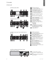
HP R/T2200 G4 NA/JP UPS
8a
8b
HP R/T3000 G4 LV NA/JP UPS
8a
8b
11
HP R/T3000 G4 HV NA/JP UPS and HP R/T3000 G4
INTL UPS
8a
8b
HP R/T2200 G4 ERM and HP R/T3000 G4 ERM
(optional battery module)
12
Connectors for battery modules
(to the UPS or to the other battery mod-
ules)
13
Connectors for automatic recognition of
battery modules
1
USB communication port
2
RS-232 communication port
3
Connector for automatic recognition of
an additional battery module
4
Slot for optional communication card
5
Connector for ROO (Remote On/Off) or
RPO (Remote Power Off) control
6
Connector for additional battery mod-
ule
7
30A outlet (L5-30R) for connection of
equipment (2U R/T3000 G4 LV NA/JP UPS
only)
8a
Group 1: Two programmable outlets for
connection of equipment
8b
Group 2: Two programmable outlets for
connection of equipment
9
Primary Group: outlets for
connection of critical equipment
10
Attached 8-ft. input power cord for AC
power source
5-20P for 2200
L5-30P for 3000
11
LED indicating SWF (site wiring fault)
alarm (Although the LED remains on
the rear panel, this feature is disabled
for low voltage models.)
12
Ground connection
1
USB communication port
2
RS-232 communication port
3
Connector for automatic recognition of an
additional battery module
4
Slot for optional communication card
5
Connector for ROO (Remote On/Off) or
RPO (Remote Power Off) control
6
Connector for additional battery module
7
16A outlet for connection of equipment
(primary group)
8a
Group 1: Two programmable outlets for
connection of equipment
8b
Group 2: Two programmable outlets for
connection of equipment
9
Primary Group: 4 outlets for
connection of critical equipment
10
Outlet for connection to AC power source
11
Ground connection


