background image

10.

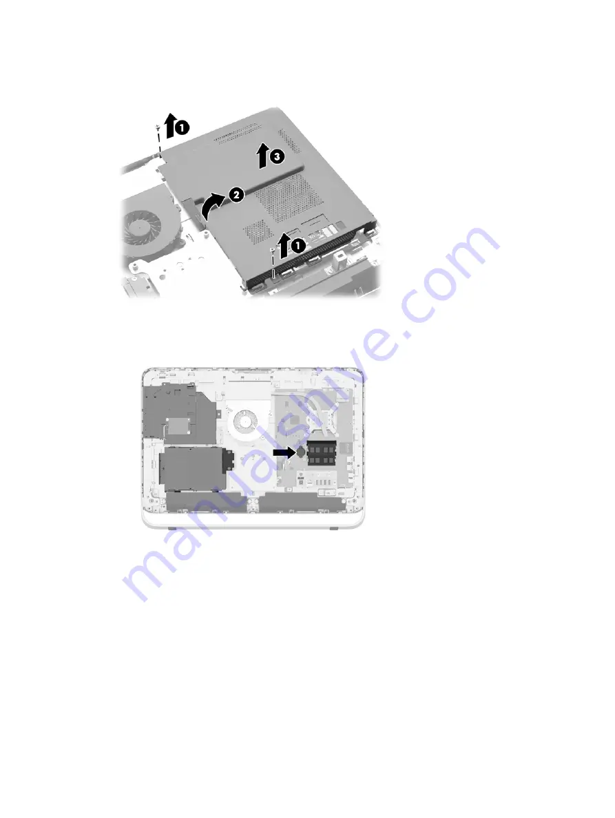
Rotate the shield to the right (2), and then lift it off the chassis (3).

Figure 3-22

  Removing the fire enclosure shield

The battery can now be seen on the left side of the memory modules.

Figure 3-23

  Locating the battery

11.

To release the battery from its holder, insert a thin metal instrument into the slot on the side of
the holder below the battery (1) and pry the battery up and out of the holder (2).

30

Chapter 3   Hardware repair and upgrade

Содержание ProOne 400 G1

Страница 1: ...Hardware Reference Guide HP ProOne 400 G1 All in One ...

Страница 2: ... Company under license The only warranties for HP products and services are set forth in the express warranty statements accompanying such products and services Nothing herein should be construed as constituting an additional warranty HP shall not be liable for technical or editorial errors or omissions contained herein This document contains proprietary information that is protected by copyright ...

Страница 3: ...s manner indicates that failure to follow directions could result in bodily harm or loss of life CAUTION Text set off in this manner indicates that failure to follow directions could result in damage to equipment or loss of information NOTE Text set off in this manner provides important supplemental information iii ...

Страница 4: ...iv About This Book ...

Страница 5: ...ecting power 12 Connecting power 12 Disconnecting power 12 Installing a cable lock 13 Installing an access panel security screw 14 Synchronizing the optional wireless keyboard and mouse 15 Removing batteries from the optional wireless keyboard or mouse 16 Attaching the computer to a mounting fixture 17 Connecting a second display 19 Locating internal components 21 Removing and installing memory 21...

Страница 6: ...inch solid state drive SSD self encrypting drive SED or solid state hybrid drive SSHD 41 Replacing the optical disc drive 43 Appendix A Electrostatic discharge 48 Preventing electrostatic damage 48 Grounding methods 48 Appendix B Computer operating guidelines routine care and shipping preparation 49 Computer operating guidelines and routine care 49 Optical disc drive precautions 50 Shipping prepar...

Страница 7: ...ntly service the PC VESA mounting holes 100 mm x 100 mm 4th generation Intel Core processors Up to 2 TB Hard Drive 180 GB Solid State Drive 256 GB Self encrypting Solid State Drive 500 GB Self encrypting Drive or 1 TB Solid State Hard Drive Optional Tray load HP SuperMulti DVD RW SATA Optical Disc Drive DVD ROM Disc Drive or Slim BDXL Blu ray Writer Intel H81 Express chipset Two SODIMM slots with ...

Страница 8: ...orts 1 USB 3 0 1 USB 3 0 fast charging 4 USB 2 0 Choice of wired or wireless keyboard and mouse Wired USB keyboard and mouse HP USB PS 2 washable keyboard and mouse Wireless keyboard and mouse Windows 7 Professional 32 bit or 64 bit or Windows 8 1 Professional 64 bit operating system Up to 89 percent energy efficient external power supply ENERGY STAR qualified EPEAT Gold registered For more inform...

Страница 9: ...2 Front components Table 1 1 Front Components Component Component 1 Dual microphone array optional 4 Power button 2 Webcam activity LED with optional webcam 5 High performance stereo speakers 3 Webcam optional Front components 3 ...

Страница 10: ...ical disc drive 6 HP 5 in 1 media card reader optional 2 Optical disc drive eject button 7 USB 3 0 port 3 Optical disc drive activity LED 8 USB 3 0 port fast charging 4 Hard disc drive activity LED 9 Microphone jack 5 HP 5 in 1 medial card reader optional LED 10 Headphone jack 4 Chapter 1 Product features ...

Страница 11: ...ss panel 7 Power supply connector 2 Access panel security screw storage position 8 Power supply DC in activity LED 3 Security screw hole locking position 9 RJ 45 Gigabit Ethernet port 4 DisplayPort port 10 4 USB 2 0 ports 5 Serial port 11 Stereo audio line out 6 Cable lock slot Rear components 5 ...

Страница 12: ...gure 1 5 Keyboard features Table 1 4 Keyboard features Component Component 1 Sleep 6 Mute Volume 2 Fast Reverse 7 Decrease Volume 3 Play Pause 8 Increase Volume 4 Stop 9 Function 5 Fast Forward 6 Chapter 1 Product features ...

Страница 13: ... G1 All in One To wake the computer from standby using the touch feature swipe the screen or touch the screen and hold for at least two seconds To wake the computer from hibernation press and release the power button This affects the HP ProOne 400 G1 All in One equipped with one of the following operating systems Windows 8 all editions 64 bit Windows 7 all editions 32 bit and 64 bit Adjusting the ...

Страница 14: ...nique serial number and a product ID number that are located on the exterior of the computer Keep these numbers available for use when contacting customer service for assistance Figure 1 7 Locating the serial number 8 Chapter 1 Product features ...

Страница 15: ...s 7 and Windows 8 each offer two methods for controlling the backlight brightness of the internal display panel These two options adjust the backlight brightness from 100 down to 30 of the full backlight brightness Windows 7 1 Select Control Panel Power Options 2 Move the screen brightness slider at the bottom of the window to make adjustments or 1 Click Start Programs Productivity and Tools HP My...

Страница 16: ...4 Move the slider to make adjustments 5 At the bottom of the window click Apply or OK to save the changes 10 Chapter 2 Display options ...

Страница 17: ...formation This guide is located on the Web at http www hp com ergo WARNING Computers that are inappropriately situated on dressers bookcases shelves desks speakers chests or carts may fall over and cause personal injury Care should be taken to route all cords and cables connected to the computer so that they can not be pulled grabbed or tripped over WARNING Energized and moving parts inside Discon...

Страница 18: ...n the rear of the computer 3 Figure 3 1 Connecting power 5 Press the power button on the top of the computer to turn it on Disconnecting power 1 Remove all removable media such as optical discs or USB flash drives from the computer 2 Turn off the computer properly through the operating system then turn off any external devices 3 Remove the cable lock if one is installed on the rear of the computer...

Страница 19: ... a key lock device that has a wire cable attached You attach one end of the cable to your desk or other stationary object and the other end of the cable to the cable lock slot on back of the computer Secure the cable lock with the key Figure 3 2 Installing a cable lock Installing a cable lock 13 ...

Страница 20: ...g the access panel Remove the T15 tamper resistant Torx security screw from the storage position in the rear of the computer and screw it into the security screw hole locking position to prevent removal of the access panel Figure 3 3 Securing the access panel 14 Chapter 3 Hardware repair and upgrade ...

Страница 21: ...less receiver 5 Press and hold the Connect button on the wireless receiver for five seconds until the blue activity LED begins blinking NOTE When the blue activity LED begins blinking you have 30 seconds to synchronize the mouse with the wireless receiver 6 Press and release the Connect button on the bottom of the mouse The blue activity LED from the wireless receiver turns off when synchronizatio...

Страница 22: ...on the underside of the keyboard 1 and lift the batteries out of the battery compartment 2 Figure 3 5 Removing batteries from the wireless keyboard To remove batteries from the wireless mouse remove the battery door on the underside of the mouse 1 and lift the batteries out of the battery compartment 2 Figure 3 6 Removing batteries from the wireless mouse 16 Chapter 3 Hardware repair and upgrade ...

Страница 23: ...2 Turn off the computer properly through the operating system then turn off any external devices 3 Disconnect the power cord from the power outlet and disconnect any external devices CAUTION Regardless of the power on state voltage is always present on the system board as long as the system is plugged into an active AC outlet You must disconnect the power cord to avoid damage to the internal compo...

Страница 24: ...nd then remove the stand 2 Figure 3 8 Removing the stand NOTE Save the screws together with the stand in case they are needed in the future 10 Set the top edge of the access panel down on the top edge of the computer chassis 1 Be sure to align the hooks on the underside of the top edge of the access panel with the top edge of the computer 11 Rotate the bottom edge of the access panel down 2 and pr...

Страница 25: ... that has a DisplayPort connector then no DisplayPort video adapter is required If you are adding a second display that does not have a DisplayPort connector you can purchase a DisplayPort video adaptor from HP for your configuration DisplayPort adapters and video cables are purchased separately HP offers the following adapters DisplayPort to VGA adapter DisplayPort to DVI adapter DisplayPort to H...

Страница 26: ...onnect a DisplayPort video adapter to the DisplayPort connector of the computer Then connect a cable VGA DVI or HDMI depending on your application between the adapter and the second display Figure 3 11 Connecting a second display using a DisplayPort adapter 4 Turn on power to the computer and the second display NOTE Use the graphics card software or the Windows Display Settings to configure the se...

Страница 27: ...e data rate 3 synchronous dynamic random access memory DDR3 SDRAM small outline dual inline memory modules SODIMMs SODIMMs The memory sockets on the system board can be populated with up to two industry standard SODIMMs These memory sockets are populated with at least one preinstalled SODIMM To achieve the maximum memory support you can populate the system board with up to 16 GB of memory DDR3 SDR...

Страница 28: ...n ECC memory technologies single sided and double sided SODIMMS SODIMMs constructed with x8 and x16 SDRAMs SODIMMs constructed with x4 SDRAMs are not supported NOTE The system will not operate properly if you install unsupported SODIMM memory HP offers upgrade memory for this computer and advises that the consumer purchase it to avoid compatibility issues with unsupported third party memory 22 Cha...

Страница 29: ...mode the maximum operational speed is determined by the slowest SODIMM in the system Installing SODIMMs There are two memory sockets on the system board To remove or install memory modules 1 Remove all removable media such as optical discs or USB flash drives from the computer 2 Turn off the computer properly through the operating system then turn off any external devices 3 Disconnect the power co...

Страница 30: ... Figure 3 13 Removing the access panel 8 Remove the three screws securing the VESA panel to the chassis 1 and then lift the panel out of the chassis 2 Figure 3 14 Removing the VESA panel 9 Remove the two screws securing the fire enclosure shield to the chassis 1 24 Chapter 3 Hardware repair and upgrade ...

Страница 31: ...ight 2 and then lift it off the chassis 3 Figure 3 15 Removing the fire enclosure shield The memory modules can now be seen in the right side of the chassis Figure 3 16 Locating the memory modules Removing and installing memory 25 ...

Страница 32: ...e with the tab on the memory socket 13 Engage the three tabs on the right edge of the fire enclosure shield with the matching slots on the right side of the chassis and rotate the fire enclosure shield down onto the chassis 14 Fasten the two screws to secure the fire enclosure shield to the chassis 15 Place the VESA panel onto the chassis and fasten the three screws to secure the VESA panel to the...

Страница 33: ...battery originally installed in the computer The computer comes with a 3 volt lithium coin cell battery WARNING The computer contains an internal lithium manganese dioxide battery There is a risk of fire and burns if the battery is not handled properly To reduce the risk of personal injury Do not attempt to recharge the battery Do not expose to temperatures higher than 60 C 140 ºF Do not disassemb...

Страница 34: ...onnect any external devices CAUTION Regardless of the power on state voltage is always present on the system board as long as the system is plugged into an active AC outlet You must disconnect the power cord to avoid damage to the internal components of the computer 4 Remove disengage any security devices that prohibit opening the computer 5 Place the computer face down on a soft flat surface HP r...

Страница 35: ...ws securing the VESA panel to the chassis 1 and then lift the panel out of the chassis 2 Figure 3 21 Removing the VESA panel 9 Remove the two screws securing the fire enclosure shield to the chassis 1 Replacing the battery 29 ...

Страница 36: ...The battery can now be seen on the left side of the memory modules Figure 3 23 Locating the battery 11 To release the battery from its holder insert a thin metal instrument into the slot on the side of the holder below the battery 1 and pry the battery up and out of the holder 2 30 Chapter 3 Hardware repair and upgrade ...

Страница 37: ...ce the VESA panel onto the chassis and fasten the three screws to secure the VESA panel to the chassis 16 Set the top edge of the access panel down on the top edge of the computer chassis 1 Be sure to align the hooks on the underside of the top edge of the access panel with the top edge of the computer 17 Rotate the bottom edge of the access panel down 2 and press it firmly onto the chassis until ...

Страница 38: ...d drive SSHD Removing a 3 5 inch hard drive 1 Remove all removable media such as optical discs or USB flash drives from the computer 2 Turn off the computer properly through the operating system then turn off any external devices 3 Disconnect the power cord from the power outlet and disconnect any external devices CAUTION Regardless of the power on state voltage is always present on the system boa...

Страница 39: ...s panel off of the computer 3 Figure 3 26 Removing the access panel The hard drive cage can now be seen in the lower left side of the chassis Figure 3 27 Locating the hard drive cage 8 Loosen the captive screw securing the hard drive cage in the chassis 1 Replacing drives 33 ...

Страница 40: ...nch hard drive in the hard drive cage Be sure to keep the screws together with the blue rubber grommets to use to install a replacement drive 11 Slide the 3 5 inch hard drive out of the hard drive cage 2 Figure 3 29 Removing the mounting screws For instructions on installing a hard drive see Installing a hard drive on page 39 34 Chapter 3 Hardware repair and upgrade ...

Страница 41: ... on state voltage is always present on the system board as long as the system is plugged into an active AC outlet You must disconnect the power cord to avoid damage to the internal components of the computer 4 Remove disengage any security devices that prohibit opening the computer 5 Place the computer face down on a soft flat surface HP recommends that you set down a blanket towel or other soft c...

Страница 42: ... of the computer 3 Figure 3 30 Removing the access panel The hard drive cage can now be seen in the lower left side of the chassis Figure 3 31 Locating the hard drive cage 8 Loosen the captive screw securing the hard drive cage in the chassis 1 36 Chapter 3 Hardware repair and upgrade ...

Страница 43: ...n the hard drive cage Be sure to keep the screws together with the blue rubber grommets to use to install a replacement drive 11 Slide the 2 5 inch drive adapter out of the hard drive cage 2 Figure 3 33 Removing the drive cage 12 Remove the four screws 1 securing the 2 5 inch drive in the drive adapter Be sure to keep the screws to use to install a replacement drive Replacing drives 37 ...

Страница 44: ...d drive out of the drive adapter 2 Figure 3 34 Removing the 2 5 inch drive adapter from the drive cage For instructions on installing a hard drive see Installing a hard drive on page 39 38 Chapter 3 Hardware repair and upgrade ...

Страница 45: ...the four mounting screws through the sides of the hard drive cage into the 3 5 inch hard drive 2 Be sure to keep the blue rubber grommets behind each screw Figure 3 35 Installing the 3 5 inch hard drive in the hard drive cage 3 With the 3 5 inch hard drive connector facing toward the center of the chassis place the hard drive cage into the chassis and slide it toward the center until it snaps into...

Страница 46: ...e access panel down 2 and press it firmly onto the chassis until it locks into place 7 Tighten the captive screws 3 to secure the access panel in place Figure 3 37 Replacing the access panel 8 Place the computer in the upright position 9 Reconnect the power cord and external devices 10 Lock any security devices that were disengaged when the access panel was removed 11 Turn on the computer 40 Chapt...

Страница 47: ...ybrid drive SSHD in the 2 5 inch drive adapter Figure 3 38 Securing the 2 5 inch hard drive in the adapter 3 Slide the 2 5 inch drive adapter into the hard drive cage 1 4 Screw the four mounting screws with grommets through the sides of the hard drive cage into the 2 5 inch drive adapter 2 Be sure to keep the blue rubber grommets behind each screw Figure 3 39 Installing the 2 5 inch drive adapter ...

Страница 48: ...he top edge of the computer 8 Rotate the bottom edge of the access panel down 2 and press it firmly onto the chassis until it locks into place 9 Tighten the captive screws 3 to secure the access panel in place Figure 3 41 Replacing the access panel 10 Place the computer in the upright position 11 Reconnect the power cord and external devices 12 Lock any security devices that were disengaged when t...

Страница 49: ...egardless of the power on state voltage is always present on the system board as long as the system is plugged into an active AC outlet You must disconnect the power cord to avoid damage to the internal components of the computer 4 Remove disengage any security devices that prohibit opening the computer 5 Place the computer face down on a soft flat surface HP recommends that you set down a blanket...

Страница 50: ... optical disc drive 8 Loosen the captive screw 1 through the optical disc drive bracket that secures the optical disc drive to the chassis NOTE The optical disc drive bracket is installed on the chassis if the model does not have an optical disc drive Remove the bracket from the chassis and follow the remaining steps using two screws from the option kit to mount the bracket to the optical disc dri...

Страница 51: ... to remove it from the chassis Figure 3 44 Removing the optical disc drive 10 Remove the two screws attaching the optical disc drive bracket to the optical disc drive Figure 3 45 Removing the optical disc drive bracket Replacing drives 45 ...

Страница 52: ...e installed in only one way 13 Tighten the captive screw 2 through the optical disc drive bracket to secure the drive to the chassis Figure 3 47 Installing the optical disc drive 14 Set the top edge of the access panel down on the top edge of the computer chassis 1 Be sure to align the hooks on the underside of the top edge of the access panel with the top edge of the computer 15 Rotate the bottom...

Страница 53: ...ace Figure 3 48 Replacing the access panel 17 Place the computer in the upright position 18 Reconnect the power cord and external devices 19 Lock any security devices that were disengaged when the access panel was removed 20 Turn on the computer Replacing drives 47 ...

Страница 54: ...several methods for grounding Use one or more of the following methods when handling or installing electrostatic sensitive parts Use a wrist strap connected by a ground cord to a grounded workstation or computer chassis Wrist straps are flexible straps with a minimum of 1 megohm 10 percent resistance in the ground cords To provide proper ground wear the strap snug against the skin Use heelstraps t...

Страница 55: ...ver cover the ventilation slots with any type of material Install or enable power management functions of the operating system or other software including sleep states When cleaning the computer turn off power to the computer and unplug the power cord before you do any of the following Wipe the exterior of the computer with a soft damp cloth as needed Using cleaning products may discolor or damage...

Страница 56: ...ce provider Shipping preparation Follow these suggestions when preparing to ship the computer 1 Back up the hard drive files on optical media or external USB drives Be sure that the backup media is not exposed to electrical or magnetic impulses while stored or in transit NOTE The hard drive locks automatically when the system power is turned off 2 Remove and store all removable media 3 Turn off th...

Страница 57: ...ng drive SED 41 2 5 inch solid state drive SSD 41 2 5 inch solid state hybrid drive SSHD 41 3 5 inch hard drive 39 access panel security screw 14 battery 27 cable lock 13 memory 23 optical disc drive 43 second display 19 internal components 21 K keyboard features 6 removing batteries 16 synchronizing wireless 15 M memory installing 23 removing 23 SODIMMs specifications 21 specifications 21 mountin...

Страница 58: ...ng 35 solid state hybrid drive SSHD 2 5 inch installing 41 2 5 inch removing 35 specifications memory 21 stand removing 17 swivel adjustment 7 synchronizing wireless keyboard and mouse 15 T tilt adjustment 7 V ventilation guidelines 49 VESA mounting holes 17 W waking the computer 7 warnings and cautions 11 52 Index ...

Отзывы: