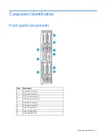
Component identification 9
Item
Description
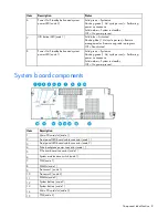
16
PCIe riser board connector (node 2)
17
System maintenance switch (node 2)
18
Drive backplane power connector (node 2)
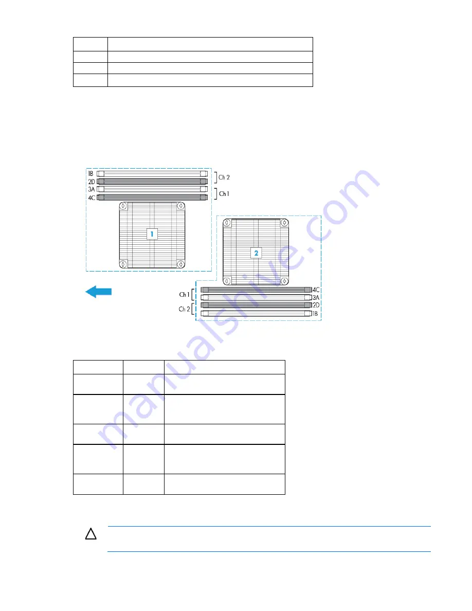
DIMM slot locations
DIMM slots are numbered sequentially (1 through 4) for each processor. The supported AMP modes use the
alpha assignments for population order, and the slot numbers designate the DIMM slot ID for spare
replacement. The arrow indicates the front of the server.
System maintenance switch
Switch
Default
Function
1
Off
Off = No function
On = iLO 4 security is disabled
2
Off
Off = System configuration can be
changed
On = System configuration is locked
5
Off
Off = Power-on password is enabled
On = Power-on password is disabled
6
Off
Off = No function
On = ROM reads configuration as
invalid
3, 4, 7, 8, 9,
10, 11, 12
—
Reserved
When the system maintenance switch position 6 is set to the On position, the system is prepared to erase all
system configuration settings from both CMOS and NVRAM.
CAUTION:
Clearing CMOS and/or NVRAM deletes configuration information. Be sure to
properly configure the server or data loss could occur.
Содержание ProLiant XL220a Gen8 v2
Страница 65: ...Support and other resources 65 ...
Страница 66: ...Support and other resources 66 ...
Страница 74: ...Index 74 W website HP 59 ...

