background image


Removal and replacement procedures  37 

Item  

Description  

SFF hard drive 5, under HDD 6 

SFF hard drive 6 

SFF hard drive 7, under HDD 8 

SFF hard drive 8 


NOTE:

 For SFF hard drive installation and cable routing, see the optional documentation on HP 

website at 

http://www.hp.com/

Front I/O board  

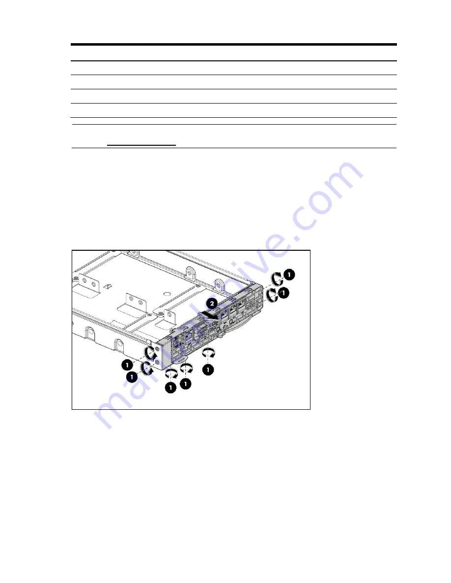
To remove the front I/O bezel assembly: 


1.


Disconnect all external cables (if connected). 

2.


Unfasten the screws that secure the front I/O bezel assembly to the tray (1). 

3.


Remove the front I/O bezel assembly (2). 

4.


Disconnect all the cables from the front I/O board. 

Figure 11 

Removing the front I/O bezel assembly 


Содержание ProLiant SL335s G7

Страница 1: ...HP ProLiant SL335s G7 Server Maintenance and Service Guide Part number 622529 002 Second edition March 2013 ...

Страница 2: ... set forth in the express warranty statements accompanying such products and services Nothing herein should be construed as constituting an additional warranty HP shall not be liable for technical or editorial errors or omissions contained herein Intel is a trademark of Intel Corporation in the U S and other countries Microsoft and Windows are U S registered trademarks of Microsoft Corporation ...

Страница 3: ...ocedures 29 Cable management 31 Cable connections 32 Hard drives 34 Front I O board 37 System board configuration 39 Processor 39 Memory 46 PCI expansion cards 49 Battery backed write cache procedures 52 System battery 53 System board removal and replacement procedure 55 Personality board 56 Power supply unit PSU 57 System fan 60 Connectors switches and LEDs 63 Connectors and components 63 Front p...

Страница 4: ... 4 HP Insight Remote Support software 75 USB support and functionality 75 USB support 75 Internal USB functionality 76 Physical and operating specifications 77 System unit 77 Documentation feedback 80 Index 81 ...

Страница 5: ... be shipped for next business day delivery Same day or four hour delivery may be offered at an additional charge where geography permits If assistance is required you can call the HP Technical Support Center and a technician will help you over the telephone HP specifies in the materials shipped with a replacement CSR part whether a defective part must be returned to HP In cases where it is require...

Страница 6: ...èces CSR sont livrées le jour ouvré suivant dans la limite des stocks disponibles et selon votre situation géographique Si votre situation géographique le permet et que vous demandez une livraison le jour même ou dans les 4 heures celle ci vous sera facturée Pour bénéficier d une assistance téléphonique appelez le Centre d assistance technique HP Dans les documents envoyés avec la pièce de rechang...

Страница 7: ... con consegna entro il giorno lavorativo seguente La consegna nel giorno stesso o entro quattro ore è offerta con un supplemento di costo solo in alcune zone In caso di necessità si può richiedere l assistenza telefonica di un addetto del centro di supporto tecnico HP Nel materiale fornito con una parte di ricambio CSR HP specifica se il cliente deve restituire dei componenti Qualora sia richiesta...

Страница 8: ... innerhalb von vier Stunden gegen einen Aufpreis verfügbar Wenn Sie Hilfe benötigen können Sie das HP technische Support Center anrufen und sich von einem Mitarbeiter per Telefon helfen lassen Den Materialien die mit einem CSR Ersatzteil geliefert werden können Sie entnehmen ob das defekte Teil an HP zurückgeschickt werden muss Wenn es erforderlich ist das defekte Teil an HP zurückzuschicken müsse...

Страница 9: ...estino al siguiente día laborable Si la situación geográfica lo permite se puede solicitar la entrega en el mismo día o en cuatro horas con un coste adicional Si precisa asistencia técnica puede llamar al Centro de asistencia técnica de HP y recibirá ayuda telefónica por parte de un técnico Con el envío de materiales para la sustitución de componentes CSR HP especificará si los componentes defectu...

Страница 10: ...onden voor levering op de eerstvolgende werkdag Levering op dezelfde dag of binnen vier uur kan tegen meerkosten worden aangeboden indien dit mogelijk is gezien de locatie Indien assistentie gewenst is belt u een HP Service Partner om via de telefoon technische ondersteuning te ontvangen HP vermeldt in de documentatie bij het vervangende CSR onderdeel of het defecte onderdeel aan HP moet worden ge...

Страница 11: ...rimeiro dia útil após o pedido Onde as condições geográficas permitirem a entrega no mesmo dia ou em quatro horas pode ser feita mediante uma taxa adicional Se precisar de auxílio entre em contato com o Centro de suporte técnico da HP para que um técnico o ajude por telefone A HP especifica nos materiais fornecidos com a peça CSR de reposição se a peça com defeito deve ser devolvida à HP Nos casos...

Страница 12: ... Customer self repair 12 ...

Страница 13: ... Customer self repair 13 ...

Страница 14: ... Customer self repair 14 ...

Страница 15: ... Customer self repair 15 ...

Страница 16: ... 1 Mandatory Parts for which customer self repair is mandatory If you request HP to replace these parts you will be charged for the travel and labor costs of this service 2 Optional Parts for which customer self repair is optional These parts are also designed for customer self repair If however you require that HP replace them for you there may or may not be additional charges depending on the ty...

Страница 17: ...ddizionali a seconda del tipo di garanzia previsto per il prodotto 3 No Non CSR Alcuni componenti HP non sono progettati per la riparazione da parte del cliente Per rispettare la garanzia HP richiede che queste parti siano sostituite da un centro di assistenza autorizzato Tali parti sono identificate da un No nel Catalogo illustrato dei componenti 1 Mandatory Zwingend Teile die im Rahmen des Custo...

Страница 18: ...ieservice voor het product 3 No Nee Sommige HP onderdelen zijn niet ontwikkeld voor reparatie door de klant In verband met de garantievoorwaarden moet het onderdeel door een geautoriseerde Service Partner worden vervangen Deze onderdelen worden in de geïllustreerde onderdelencatalogus aangemerkt met Nee 1 Mandatory Obrigatória Peças cujo reparo feito pelo cliente é obrigatório Se desejar que a HP ...

Страница 19: ...Illustrated parts catalog 19 ...

Страница 20: ...FF 574270 001 Optional2 Hard drive SATA 1TB 7 2K LFF 574271 001 Optional2 Hard drive SAS 300GB 15K 6G LFF 586009 001 Optional2 Hard drive SAS 600G 15K 6G LFF 575056 001 Optional2 Hard drive SATA 2TB 7 2K 3G LFF 575262 001 Optional2 Hard drive SAS 2TB 15K 6G LFF 575057 001 Optional2 Hard drive SATA 160GB 7 2K SFF 575053 001 Optional2 Hard drive SATA 500GB 7 2K SFF 575054 001 Optional2 Hard drive SA...

Страница 21: ...E 9 Kit 595101 001 Mandatory1 HP 4GB 2Rx8 PC3 10600E 9 Kit 595102 001 Mandatory1 HP 4GB 1Rx4 PC3 10600R 9 Kit 653399 001 Mandatory1 HP 2GB 2Rx4 PC3 10600R 9 Kit 595094 001 Mandatory1 6 Processors optional series Processor AMD 4171EHE 2 1GHz 6M 6c 50W 629819 001 Optional2 Processor AMD 4176HE 2 4GHz 6M 6c 50W 637341 001 Optional2 Processor AMD 4130 2 6GHz 6M 4c 75W 629820 001 Optional2 Processor AM...

Страница 22: ...your product 3 No Some HP parts are not designed for customer self repair In order to satisfy the customer warranty HP requires that an authorized service provider replace the part These parts are identified as No in the Illustrated Parts Catalog 1 Mandatory Obligatoire Pièces pour lesquelles la réparation par le client est obligatoire Si vous demandez à HP de remplacer ces pièces les coûts de dép...

Страница 23: ...e estos componentes tendrá que hacerse cargo de los gastos de desplazamiento y de mano de obra de dicho servicio 2 Optional Opcional componentes para los que la reparación por parte del usuario es opcional Estos componentes también están diseñados para que puedan ser reparados por el usuario Sin embargo si precisa que HP realice su sustitución puede o no conllevar costes adicionales dependiendo de...

Страница 24: ...e a HP as substitua pode haver ou não a cobrança de taxa adicional dependendo do tipo de serviço de garantia destinado ao produto 3 No Nenhuma Algumas peças da HP não são projetadas para o reparo feito pelo cliente A fim de cumprir a garantia do cliente a HP exige que um técnico autorizado substitua a peça Essas peças estão identificadas com a marca No Não no catálogo de peças ilustrado ...

Страница 25: ...site at http www8 hp com us en support drivers html If the problem cannot be resolved at the website call 1 800 633 3600 For more information about Care Packs see the HP website at http pro aq sama houston hp com services cache 10950 0 0 225 121 html Before you contact HP Be sure to have the following information available before you call HP Technical support registration number if applicable Prod...

Страница 26: ... rack and is positioned on a flat stable surface Hardware configuration tools You need the following items for some procedures T 10 T 15 wrench Flat blade screwdriver The following references and software tools may also be used HP ProLiant SL335s G7 Server User Guide IPMI Event Log Diagnostics Software Hardware configuration information Electrostatic discharge information An electrostatic discharg...

Страница 27: ...stallation removal procedure first and make sure you understand them before you begin Post installation procedure Observe the following items after installing or removing a server component 1 Be sure all components are installed according to the described step by step instructions 2 Check to make sure you have not left loose tools or parts inside the server 3 Reinstall the PCI riser peripherals an...

Страница 28: ... consideration of equipment nameplate ratings should be used when addressing this concern Reliable Earthing Reliable earthing of rack mounted equipment should be maintained Particular attention should be given to supply connections other than direct connections to the branch circuit e g use of power strips Symbols on equipment The following symbols may be placed on equipment to indicate the presen...

Страница 29: ...move all power from the system disconnect all power cords from the server To power down the server 1 Shut down server as directed by the operating system documentation 2 Press the power button to toggle to Standby This places the server in standby mode changing the power LED indicator to amber In this mode the main power supply output is disabled Standby does not completely disable or remove power...

Страница 30: ...eplacement procedures 30 Figure 1 Removing the left server Figure 2 Removing the right server To replace the system tray 1 Insert the system tray into the chassis 2 Rotate the tray handle to lock the power connector ...

Страница 31: ...expansion cards or memory modules Printed circuit cards are not designed to withstand excessive pressure Keep cables clear of sliding or moveable parts to prevent cutting or crimping When folding a flat ribbon cable never fold to a sharp crease Sharp creases may damage the wires Some flat ribbon cables come pre folded Never change the folds on these cables Do not sharply bend any cable A sharp ben...

Страница 32: ...ector NEVER pull on the cable Pulling on the cable could damage the cable and result in a failed power supply Figure 5 Unplugging power cables Cable connections The following table provides information about cable connector Table 1 Cable connection for SATA LFF HDD 3 5 inch hard disk Cable From To SATA cable 1 2 3 4 two branches each cable Power cable HDD 1 2 3 4 P1 P2 P3 P4 on personality board D...

Страница 33: ...able HDD7 P4 on the personality board Data cable J5 on P410 card Power cable HDD8 P4 on the personality board Data cable J5 on P410 card Table 4 Cable connections Cable From To VGA cable J10 on the front I O board J40 on the system board Serial cable J25 on the system board USB cable 1 J24 bottom connector on the system board USB cable 2 J24 top connector on the system board Front I O cable J3 on ...

Страница 34: ...SAS and SATA hard disk drives LFF hard drive 3 5 inch hard drive Figure 6 LFF hard drive locations Item Description 1 LFF SAS SATA hard drive 1 2 LFF SAS SATA hard drive 2 3 LFF SAS SATA hard drive 3 4 LFF SAS SATA hard drive 4 To remove an LFF hard drive 1 Slide the HDD carrier latches to unlock the HDD handle 2 Raise the HDD handle 3 Lift the HDD assembly out of the tray 4 Rotate the HDD carrier...

Страница 35: ...te the HDD carrier handle up 3 Insert the HDD carrier and align the four pins 4 Rotate the HDD carrier handle down 5 Lock the HDD carrier latches Figure 8 Installing an LFF hard drive IMPORTANT Do not discard the hard drive blank If the drive is removed in the future you must reinstall the hard drive blank to maintain proper system airflow ...

Страница 36: ...connections Figure 10 identifies the SFF hard drive numbering based on system board SATA port connections Figure 9 SFF hard drive locations P410 controller connections Figure 10 SFF hard drive location System board SATA port connections Item Description 1 SFF hard drive 1 under HDD 2 2 SFF hard drive 2 3 SFF hard drive 3 under HDD 4 4 SFF hard drive 4 ...

Страница 37: ... cable routing see the optional documentation on HP website at http www hp com Front I O board To remove the front I O bezel assembly 1 Disconnect all external cables if connected 2 Unfasten the screws that secure the front I O bezel assembly to the tray 1 3 Remove the front I O bezel assembly 2 4 Disconnect all the cables from the front I O board Figure 11 Removing the front I O bezel assembly ...

Страница 38: ...n the screws that secure the front I O board to the front I O bezel 2 Remove the front I O board Figure 12 Removing the front I O board To install the front I O board 1 Align the front I O board to the front I O bezel 2 Fasten the screws Figure 13 Installing the front I O board ...

Страница 39: ...G7 nodes supports sixteen processor operation With two processors installed each node supports boot functions through the processor installed in processor socket 1 4 cores or 6 cores per socket 512KB L2 cache per core 6MB shared L3 cache Common socket C32 95W 75W 50W and 32W TDP power segments supported Support for future socket compatible processor Processor power modules PPMs are embedded onto s...

Страница 40: ...ld be tightened and loosened in opposite sequence Do not overtighten the screws as this can damage the system board connectors or screws A maximum torque of 6 8 in lb is set for the system CAUTION Place the heatsink down in an upright position with the thermal patch facing upward Do not let the thermal patch touch the work surface 1 Loosen the first screw about three quarters out then loosen the s...

Страница 41: ...der on the processor to ensure proper thermal bonding between the processor and the heatsink To remove a processor 1 Disengage the load lever 2 Lift the retention plate to expose the socket body 3 Grasp the processor by its edges and lift it out of its socket Figure 17 Removing a processor CAUTION The pins of the socket are very fragile Do not bend or damage them CAUTION Place the processor on a s...

Страница 42: ...llow the instructions to prevent damage to the pins in the processor socket To install a new processor 1 Open the processor retaining latch and the processor socket retaining bracket Figure 18 Open the processor socket IMPORTANT Be sure the processor remains inside the processor installation tool 2 If the processor has separated from the installation tool carefully reinsert the processor in the to...

Страница 43: ...ool with the socket and install the processor Figure 20 Installing a processor 4 Press down firmly until the processor installation tool clicks and separates from the processor and then remove the processor installation tool Figure 21 Removing the processor installation tool ...

Страница 44: ...st apply thermal interface material To apply the thermal grease compound 1 Use the alcohol pad provided in the spare part kits or a clean cloth dipped in rubbing alcohol to clean the contact surface on the heatsink and on the new processor Wipe the contact surfaces several times to make sure that no particles or dust contaminants are evident CAUTION HP recommends using Shin Etsu X 23 7783D thermal...

Страница 45: ... processor pins or the system board base which can cause electrical shorts that damage the system To install the heatsink CAUTION To prevent overheating or a possible system crash use only a heatsink model specified for the HP ProLiant SL335s G7 Server CAUTION Heatsink screws should be tightened and loosened in opposite sequence Do not overtighten the screws as this can damage the system board con...

Страница 46: ...opulation see table below 2 channels per processor 3 DIMMs per channel DPC Unganged DIMM population support ganged no longer supported RAS Advanced ECC Online Spare DIMM 0 is the furthest to the CPU and DIMM2 is the closest from the CPU for each channel Channel B is the closest to the CPU and channel A is the furthest from the CPU Installing the DIMMs from DIMM0 a QR DIMM module can only inserted ...

Страница 47: ... populated DIMM type DIMM0 DIMM1 DIMM2 3 1 UDDR SR DR 3 2 UDDR SR DR SR DR Figure 25 DIMM slots Figure 26 DIMM order To remove a memory module 1 Completely open the holding clips securing the module 2 Gently pull the memory module upward to remove it from the slot ...

Страница 48: ... the DIMM slot and then press the module fully into the slot 2 Firmly press the holding clips inward to secure the memory module in place Figure 28 Installing a memory module CAUTION The memory slots are structured to ensure proper installation If you insert a memory module but it does not fit easily into the slot you may have inserted it incorrectly Double check the orientation of the module and ...

Страница 49: ...llation on the system board Figure 29 System board PCI expansion slot To install the PCIe riser card 1 Align the riser card to the PCIe bracket 2 Fasten the screws to secure the riser card to the PCIe bracket Figure 30 Installing the riser card 3 Install the PCIe card to the riser slot 4 Fasten the screw to secure the PCIe card to the PCIe bracket ...

Страница 50: ...val and replacement procedures 50 Figure 31 Installing a PCIe card 5 Install the small bracket to the system board for PCIe card assembly installation Figure 32 Installing the small bracket on the left tray ...

Страница 51: ...ure 33 Installing the small bracket on the right tray 6 Align the PCIe card assembly to the x24 riser slot on the system board and install 7 Fasten the screws as described in below figure Figure 34 Installing the PCIe assembly on the left tray ...

Страница 52: ...placement procedures 52 Figure 35 Installing the PCIe assembly to the right tray Battery backed write cache procedures 1 Align the BBWC bracket to the tray and fasten the screws Figure 36 Installing the BBWC bracket ...

Страница 53: ...n the direction of the arrow Figure 37 Installing the BBWC System battery The server uses nonvolatile memory that requires a battery to retain system information when power is removed This 3 volt lithium coin cell battery is located on the system board Figure 38 System battery location ...

Страница 54: ...ng to manufacturer s instructions CAUTION Loss of BIOS settings occurs when the battery is removed You must reconfigure BIOS settings whenever you replace the battery NOTE If the server no longer automatically displays the correct date and time you may need to replace the system battery Under normal usage battery life is five to ten years To replace the system battery 1 Release a battery push the ...

Страница 55: ...Disconnect all cables from the system board 2 Remove the six screws that secure the system board to the tray 3 Release the system board from the tray Figure 40 Removing the system board IMPORTANT Do not discard the screws If the system board is removed you must keep them for future use To replace the system board 1 Put the system board in the tray The screw holes on the tray should align with the ...

Страница 56: ...t secure the personality board to the tray 3 Release the personality board from the tray Figure 42 Removing the personality board To install the personality board 1 Put the personality board in the tray The screw holes on the tray should align with the holes on the personality board 2 Fasten the screws to secure the personality board to the tray 3 Connect all cables that related to the personality...

Страница 57: ...server enclosure Figure 44 Power supply unit WARNING Take note of the following reminders to reduce the risk of personal injury from electric shock hazards and or damage to the equipment Installation of power supply units should be referred to individuals who are qualified to service server systems and are trained to deal with equipment capable of generating hazardous energy levels DO NOT open the...

Страница 58: ...backplane 4 Remove the PSU backplane 5 Reinstall the top cover to the power supply cage 6 Fasten the screw to secure the top cover to the power supply cage Figure 45 Removing the PSU backplane To replace the PSU backplane 1 Unfasten the screw as shown in below figure 2 Remove the top cover from the power supply cage 3 Install the PSU backplane 4 Connect all cables that related to the PSU backplane...

Страница 59: ...rt colored button on the power supply latch 3 Slide the power supply out of the power supply bay Figure 47 Removing the power supply To replace the power supply 1 Align the power supply edge card connector with the open slot of power supply cage 2 Slide the power supply into the power supply bay until it snaps into place 3 Reinstall the power cable to the power supply ...

Страница 60: ...stalling the power supply System fan The server has eight system fans located on the rear panel of chassis The figure below identifies the system fans by their device number Figure 49 System fan location Item Description 1 Fan 1 2 Fan 2 3 Fan 3 4 Fan 4 ...

Страница 61: ...tem fan can be installed to allow the server to operate properly in case a system fan becomes defective To remove the system fan 1 Squeeze the two release tabs on the system fan together to release it from the chassis 2 Remove the system fan away from the chassis Figure 50 Removing the system fan ...

Страница 62: ...Removal and replacement procedures 62 To replace the system fan 1 Align the fan to the fan bay 2 Push to slide the fan until it snaps into place Figure 51 Installing the system fan ...

Страница 63: ...anel of the HP ProLiant SL335s G7 Server and the rear panel of the HP ProLiant s6500 Chassis Connectors and components Front panel components Figure 52 Front panel components of SL335s G7 server system Item Description 1 Serial port 2 VGA port 3 USB 2 0 ports 4 iLO 3 connector from left to right NIC 1 connector NIC 2 connector 5a Server handle 5b Server latch 6 Power LED Switch 7 Health LED 8 UID ...

Страница 64: ...1 Server 3 12 Server 4 13 Server 5 14 Server 6 15 Server 7 16 Server 8 Rear panel components Figure 53 Rear panel components of s6500 chassis Item Description 1 Power supply 1 2 Power supply 2 3 Power supply 3 4 Power supply 4 5 UID LED switch 6 Fan 1 7 Fan 2 8 Fan 3 9 Fan 4 ...

Страница 65: ...tem board components Item Designator Description 1 J40 VGA port 2 J25 Serial port RJ45 type 3 SW2 Power button 4 J19 Gigabit LAN connectors 5 J24 Top iLO 3 Port Bottom USB 2 0 ports 6 SW3 UID LED switch 7 J60 CMOS jumper 8 SW1 System maintenance switch 9 U59 ATI RN50 video controller 10 J52 Internal USB port 11 BT1 Battery ...

Страница 66: ...27 CPU1 DIMM VRD CPU1 DIMM VRD CPU1 DIMM VRD controller 15 J27 RPS connector 16 J26 Power connector 17 U32 U12 U21 U22 U23 U24 CPU2 VRD CPU2 VRD CPU2 VRD CPU2 VRD CPU2 VRD CPU2 VRD 18 XU2 Processor 2 socket 19 J9 J8 J7 J12 J11 J10 CPU2 DDR3 DIMM 1A slot from top to bottom CPU2 DDR3 DIMM 2E slot CPU2 DDR3 DIMM 3C slot CPU2 DDR3 DIMM 4B slot CPU2 DDR3 DIMM 5F slot CPU2 DDR3 DIMM 6D slot 20 XU1 Proce...

Страница 67: ...board failure leave the TPM installed and remove the system board Contact an HP authorized service provider for a replacement system board and TPM board Jumpers and switches Table 5 System configuration jumper settings Jumper Status J60 1 2 default setting 2 3 clear CMOS All switches are off as default Table 6 System maintenance switch Pos Description Definition 1 iLO Security override OFF normal ...

Страница 68: ...ED indicators This section contains illustration and descriptions of external status LED indicators located on the on the front panel of the HP ProLiant SL335s G7 Server and the rear panel of the HP ProLiant s6500 Chassis These LED indicators aid in problem diagnosis by indicating the status of system components and operations of the server Front panel LED indicators The front panel LED indicators...

Страница 69: ...r locations Table 7 Health LED indicator status Components Status Description Health LED indicator Flashing red Critical system failure detected Flashing red System degrade Green System in on and no failure detected Off System is off and there is no failure prior to system power off ...

Страница 70: ...s 70 Front UID LED indicator Figure 56 Front UID LED indicator locations Table 8 UID LED indicator status Components Status Descriptions UID LED indicator Blue Identification Flashing blue System is being remotely managed Off Off ...

Страница 71: ...r LED on the front panel Figure 57 Power LED indicator locations Table 9 Power LED indicator status Component Status Description Power LED indicator Steady green The server is operating normally Steady amber The server is system off or in hibernation with AC power Off The server is system off without AC power ...

Страница 72: ...y identification of the unit and indicates if the unit is being remotely managed Figure 58 Rear UID LED indicator locations Table 10 UID LED indicator status Component Status Description UID LED indicator Blue Identification Flashing blue Any system in the chassis is being remotely managed Off Off ...

Страница 73: ...U is a configuration utility embedded in ProLiant servers that performs a wide range of configuration activities that can include the following Configuration system devices and installed options Enabling and disabling system features Displaying system information Selecting the primary boot controller Configuring memory options Language selection For more information on RBSU see the HP ProLiant SL3...

Страница 74: ...oundation suite for ProLiant Array Diagnostic Utility The HP Array Diagnostics Utility is a web based application that creates a report of all HP storage controllers and disk drives This report provides vital information to assist in identifying faults or conditions that may require attention ADU can be accessed from the SmartStart CD or downloaded from the HP website http www hp com HP Systems In...

Страница 75: ...er environments and is integrated with HP Systems Insight Manager SIM It provides comprehensive remote monitoring notification advisories dispatch and proactive service support for nearly all HP servers storage network and SAN environments plus selected Dell and IBM Windows servers that have a support obligation with HP It also enables HP to deliver higher levels of proactive support in line with ...

Страница 76: ...or use of a permanent USB key installed in the internal connector avoiding issues of clearance on the front of the rack and physical access to secure data For additional security external USB functionality can be disabled through RBSU Disabling external USB support in RBSU disables the USB connectors on the local I O cable Internal USB functionality is unaffected ...

Страница 77: ...rd installation supports PCIe x8 riser PCIe x16 riser Memory Each tray supports 12 DDR3 240 pin R DIMM and 8 DDR3 240 pin U DIMM slots 6 DIMMs per CPU up to 64 128GB R DIMM3 800 1067 1333 memory up to 16 32GB U DIMM3 800 1067 1333 memory NOTE Support two UDIMMs per channel for a total of eight DIMMs per tray Default media storage SAS SATA LFF hard drive Optional media storage Four bays HDD cage fo...

Страница 78: ...0 ft 1 0 C per every 305 m above sea level to a maximum of 10 000 ft 3050 m no direct sustained sunlight Maximum rate of change is 18 F hr 10 C hr The upper limit may be limited by the type and number of options installed System performance may be reduced if operating with a fan fault or above 86 F 30 C System inlet temperature Nonoperating 40 to 140 F 40 to 60 C Maximum rate of change is 36 F hr ...

Страница 79: ... CISPR 22 EN55022 EN55024 FCC CFR 47 Pt 15 ICES 003 CNS13438 GB9254 K22 K24 EN 61000 3 2 EN 61000 3 3 EN 60950 1 IEC 60950 1 Table 14 Hot plug power supply specifications Item Description Dimensions H x W x D 38 48 mm x 86 36 mm x 190 52 mm Weight approximate 1 1 kg Input requirements Rated line voltage per power supply 90 to 140 VAC 180 to 264 VAC Rated input frequency 47 to 63 Hz Rated input cur...

Страница 80: ...oviding documentation that meets your needs To help us improve the documentation send any errors suggestions or comments to Documentation Feedback mailto docsfeedback hp com Include the document title and part number version number or the URL when submitting your feedback ...

Страница 81: ...0 hardware configuration memory 46 processor 39 system battery 53 System fan 60 hardware configuration references 26 hardware configuration PCI expansion cards 49 Hardware configuration tools 26 hardware specifications I O ports 77 LAN controller 77 memory 77 power supply unit 77 processor socket 77 processor support 77 status LED indicators 77 thermal solution 77 Hardware Specifications chipset 7...

Страница 82: ...6 Personality board installing 56 physical dimensions system board 78 Power supply spare part number 21 power supply unit See PSU Power system health LED indicator 71 power down procedures 29 processor applying thermal grease 44 installing 42 removing 41 Processor heatsink spare part number 21 processor socket specification 77 Processors spare part number 21 PSU removing 59 replacement warnings 57...

Страница 83: ...ure front panel 63 rear panel 64 system board components 65 system tray removing 29 replacing 30 System Unit specifications 77 Systems Insight Manager 74 T thermal solution 77 tools 73 troubleshooting 73 U USB support 75 utilities 73 W warnings battery replacement 54 PSU replacement 57 warranty 5 ...

Отзывы: