Removal and replacement procedures 30
5.
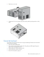
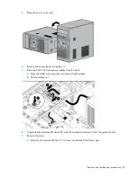
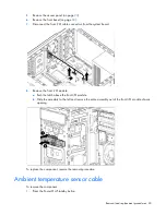
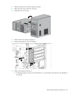
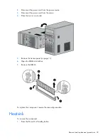
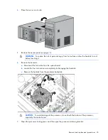
Remove the access panel (on page
6.
Remove the front bezel (on page
7.
Disconnect the front I/O cable connectors from the system board.
8.
Remove the front I/O module:
a.
Push the latch above the front I/O module.
b.
Slide the assembly to the left and remove the entire assembly out of the front I/O module chassis
opening.
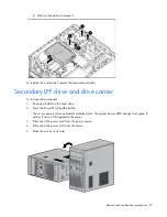
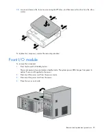
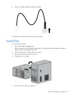
To replace the component, reverse the removal procedure.
Ambient temperature sensor cable
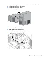
To remove the component:
1.
Press the Power On/Standby button.
Содержание ProLiant ML10
Страница 12: ...Customer self repair 12 ...
Страница 13: ...Customer self repair 13 ...
Страница 14: ...Customer self repair 14 ...
Страница 17: ...Illustrated parts catalog 17 System components ...
Страница 62: ...Component identification 62 Fan locations Item Description 1 Rear system fan 2 Processor heatsink fan assembly ...
Страница 65: ...Cabling 65 Ambient temperature sensor cabling Fan cabling System fan ...
Страница 70: ...Acronyms and abbreviations 70 SFF small form factor SIM Systems Insight Manager USB universal serial bus ...

