Removal and replacement procedures 23
•
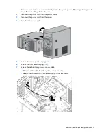
Remove the front bezel (on page
Power down the server
Before powering down the server for any upgrade or maintenance procedures, perform a backup of critical
server data and programs.
WARNING:
To reduce the risk of personal injury, electric shock, or damage to the equipment,
remove the power cord to remove power from the server. The front panel Power On/Standby
button does not completely shut off system power. Portions of the power supply and some internal
circuitry remain active until AC power is removed.
IMPORTANT:
When the server is in standby mode, auxiliary power is still being provided to the
system.
To power down the server, use one of the following methods:
•
Press and release the Power On/Standby button.
This method initiates a controlled shutdown of applications and the OS before the server enters standby
mode.
•
Press and hold the Power On/Standby button for more than 4 seconds to force the server to enter
standby mode.
This method forces the server to enter standby mode without properly exiting applications and the OS.
If an application stops responding, you can use this method to force a shutdown.
•
Use a virtual power button selection through iLO 3.
This method initiates a controlled remote shutdown of applications and the OS before the server enters
standby mode.
Before proceeding, verify the server is in standby mode by observing that the system power LED is amber.
Remove the access panel
CAUTION:
For proper cooling, do not operate the server without the access panel, baffles,
expansion slot covers, or blanks installed. If the server supports hot-plug components, minimize
the amount of time the access panel is open.
1.
Press the Power On/Standby button.
The server powers down and enters standby mode. The system power LED changes from green to
amber. Power is still applied to the server.
2.
Disconnect the power cord from the power source.
3.
Disconnect the power cord from the server.
Содержание ProLiant ML10
Страница 12: ...Customer self repair 12 ...
Страница 13: ...Customer self repair 13 ...
Страница 14: ...Customer self repair 14 ...
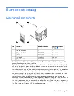
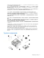
Страница 17: ...Illustrated parts catalog 17 System components ...
Страница 62: ...Component identification 62 Fan locations Item Description 1 Rear system fan 2 Processor heatsink fan assembly ...
Страница 65: ...Cabling 65 Ambient temperature sensor cabling Fan cabling System fan ...
Страница 70: ...Acronyms and abbreviations 70 SFF small form factor SIM Systems Insight Manager USB universal serial bus ...

