


System Board
Description
Spare part number
System board (includes replacement thermal material)
665465-001
The system board is secured with seven screws and is located under the system board cover.
To remove the system board:
1.
Prepare the computer for disassembly (see
Preparing to Disassemble the Computer
on page 33
).
2.
Remove the rear cover (see
Rear Cover on page 34
).
3.
Remove the system board cover (see
System Board Cover on page 49
).
4.
Remove the heat sink (see
Heat Sink (Thermal Module) on page 58
).
5.
Remove the processor (see
Processor on page 60
).
6.
Remove the memory modules (see
Memory on page 51
).
7.
Remove the WLAN module (see
WLAN Module on page 53
).
8.
Disconnect all cables from the system board, noting their location for reinstallation.
9.
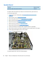
Remove the seven torx screws (circled in image) that secure the system board to the computer.
10.
Lift the system board straight up and out of the computer.
Figure 7-37
Removing the system board
To install the system board, reverse the removal procedures.
68
Chapter 7 Removal and Replacement Procedures All-in One (AIO) Chassis


