background image

b.

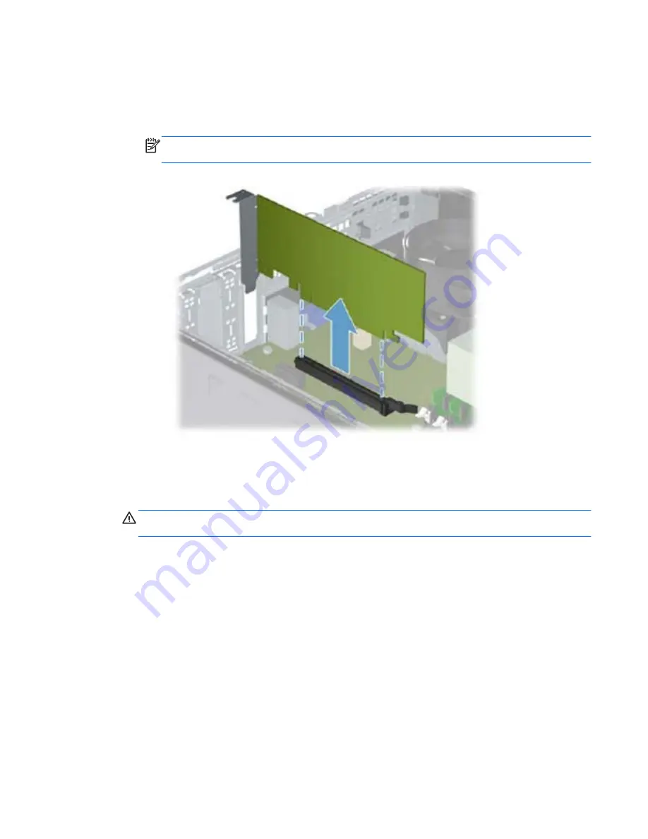
If you are removing a PCI Express x16 card, pull the retention arm on the back of the
expansion socket away from the card and carefully rock the card back and forth until the
connectors pull free from the socket. Pull the expansion card straight up from the socket
then away from the inside of the chassis to release it from the chassis frame. Be sure not to
scrape the card against the other components.

NOTE:

PCI cards and PCI Express x1 cards do not have the retention arm. PCI Express

X16 card is shown below.

Figure 8-11

  Removing a standard PCI expansion card

6.

Store the removed card in anti-static packaging.

7.

If you are not installing a new expansion card, install an expansion slot cover to close the open
slot.

CAUTION:

After removing an expansion card, you must replace it with a new card or

expansion slot cover for proper cooling of internal components during operation.

Expansion Card

91

Содержание Pro 3410

Страница 1: ...Guide HP Pro 3400 Microtower Business PC HP Pro 3405 Microtower Business PC HP Pro 3410 Microtower Business PC HP Pro 3410 Small Form Factor Business PC HP Pro 3500 Microtower Business PC HP Pro 3505 Microtower Business PC ...

Страница 2: ...ing such products and services Nothing herein should be construed as constituting an additional warranty HP shall not be liable for technical or editorial errors or omissions contained herein This document contains proprietary information that is protected by copyright No part of this document may be photocopied reproduced or translated to another language without the prior written consent of Hewl...

Страница 3: ...ollow directions could result in bodily harm or loss of life CAUTION Text set off in this manner indicates that failure to follow directions could result in damage to equipment or loss of information NOTE Text set off in this manner provides important supplemental information iii ...

Страница 4: ...iv About This Book ...

Страница 5: ...s 6 Protecting the Software 6 3 Computer Setup F10 Utility 7 Computer Setup F10 Utilities 7 Using Computer Setup F10 Utilities 8 Computer Setup File 9 Computer Setup Storage 10 Computer Setup Security 12 Computer Setup Power 15 Computer Setup Advanced 16 Recovering the Configuration Settings 17 4 Illustrated parts catalog 18 Microtower Chassis Spare Parts 18 Computer Major Components 18 Cables 21 ...

Страница 6: ...amage to Equipment 37 Personal Grounding Methods and Equipment 37 Grounding the Work Area 38 Recommended Materials and Equipment 38 Operating Guidelines 39 Routine Care 39 General Cleaning Safety Precautions 39 Cleaning the Computer Case 39 Cleaning the Keyboard 40 Cleaning the Monitor 40 Cleaning the Mouse 41 Service Considerations 41 Power Supply Fan 41 Tools and Software Requirements 41 Screws ...

Страница 7: ...itch LED Assembly 67 System Fan 69 Fan Sink Assembly 71 Processor 72 Power Supply 76 System Board 77 Battery 78 8 Removal and Replacement Procedures Small Form Factor SFF Chassis 80 Preparation for Disassembly 80 Access Panel 81 Front Bezel 83 Memory 84 DDR3 SDRAM DIMMs 84 Populating DIMM Sockets 85 Removing DIMMs 86 Expansion Card 89 Cable Management 93 Cable Connections 94 Drives 95 Drive Positi...

Страница 8: ...Requirements 126 General Requirements 126 Japanese Power Cord Requirements 126 Country Specific Requirements 127 Appendix C POST Error Messages 128 POST Numeric Codes and Text Messages 129 Interpreting POST Diagnostic Front Panel LEDs and Audible Codes 137 Appendix D Troubleshooting Without Diagnostics 141 Safety and Comfort 141 Before You Call for Technical Support 141 Helpful Hints 142 Solving G...

Страница 9: ...ving Internet Access Problems 174 Solving Software Problems 176 Contacting Customer Support 177 Appendix E Password Security and Resetting CMOS 178 Resetting the Password Jumper 179 Clearing and Resetting the CMOS 179 Appendix F Backup and Recovery 181 Windows 7 Backup and Recovery 181 Backing Up Your Information 181 Performing a Recovery 183 Using the Windows Recovery Tools 183 Using F11 184 Usin...

Страница 10: ...x ...

Страница 11: ...tScribe drive SuperMulti DVD drive DVD ROM drive Integrated Realtek RTL8171E Gigabit Ethernet Controller HP 3500 and HP Pro 3400 Pro only or Integrated Realtek RTL8111E PCI E Gigabit Ethernet Controller HP 3405 Pro only and Integrated Realtek RTL8111EL PCI E Gigabit Ethernet Controller HP 3410 Pro only 10 USB 2 0 ports on HP Pro 3500 and HP Pro 3400 5 on board header including 2 on Front I O 4 rea...

Страница 12: ...ireless NIC 802 11b g n Mini Card 1x1 optional for HP Pro 3500 3400 and 3405 5 1 channel audio HP Pro 3500 3400 and 3410 7 1 channel audio HP Pro 3405 Genuine Windows 7 versions FreeDOS or RedFlag Linux 2 Chapter 1 Product Features ...

Страница 13: ...2 Power Supply 7 USB Scroll Mouse 3 Rear I O includes 4 USB 2 0 ports RJ 45 network interface DVI and VGA video interfaces microphone jack audio in out jacks 5 1 channel audio out 8 HP USB Standard Value Keyboard 4 Front I O includes 2 USB 2 0 ports dedicated headphone output microphone jack 9 Display sold separately 5 1 internal 3 5 hard drive bays 1 HP Pro 3500 3400 and 3405 only HP Pro 3410 has...

Страница 14: ...ar I O includes 3 PCIe x1 slots 1 PCIe x16 slot 1 miniPCI slot 4 USB 2 0 ports RJ 45 network interface DVI and VGA video interfaces microphone jack audio in out jacks 5 1 channel audio out 8 HP USB Standard Value Keyboard 4 Front I O includes 2 USB 2 0 ports dedicated headphone output 9 Monitor sold separately 5 HP 6 in 1 Media Card Reader some models 4 Chapter 1 Product Features ...

Страница 15: ...em The first time you turn on the computer the operating system is installed automatically This process takes about 5 to 10 minutes depending on which operating system is being installed Carefully read and follow the instructions on the screen to complete the installation CAUTION Once the automatic installation has begun DO NOT TURN OFF THE COMPUTER UNTIL THE PROCESS IS COMPLETE Turning off the co...

Страница 16: ...software including support software for the operating system from http www hp com support Select your country and language select Download drivers and software and firmware enter the model number of the computer and press Enter Accessing Disk Image ISO Files There are disk image files ISO files included on your PC that contain the installation software for additional software These CD image files ...

Страница 17: ... messages Post Messages Disabled suppresses most POST messages such as memory count product name and other non error text messages If a POST error occurs the error is displayed regardless of the mode selected To manually switch to Post Messages Enabled during POST press any key except F1 through F12 Establish an Ownership Tag the text of which is displayed each time the system is turned on or rest...

Страница 18: ...een to access the utility 3 If you pressed Esc press F10 to enter Computer Setup 4 A choice of five headings appears in the Computer Setup Utilities menu File Storage Security Power and Advanced 5 Use the arrow left and right keys to select the appropriate heading Use the arrow up and down keys to select the option you want then press Enter To return to the Computer Setup Utilities menu press Esc ...

Страница 19: ...l if applicable Integrated MAC address for embedded enabled NIC if applicable System BIOS includes family name and version Chassis serial number Asset tracking number About Displays copyright notice Set Time and Date Allows you to set system time and date Apply Defaults and Exit Applies the currently selected default settings and clears any established passwords Ignore Changes and Exit Exits Compu...

Страница 20: ... serial number Storage Options SATA Emulation Allows you to choose how the SATA controller and devices are accessed by the operating system There are two supported options IDE and AHCI The default is set based on the Feature Byte code stored in the SMBIOS Type11 Feature Byte string as follows Feature Byte Default FBC_SATA_RAID RAID FBC_SATA_AHCI AHCI FBC_SATA_IDE IDE Otherwise none found Platform ...

Страница 21: ...ootable operating system image Each device on the list may be individually excluded from or included for consideration as a bootable operating system source Specify the order of attached hard drives The first hard drive in the order will have priority in the boot sequence and will be recognized as drive C if any devices are attached NOTE You can use F5 to disable individual boot items as well as d...

Страница 22: ...n will only appear when at least one drive that supports the DriveLock feature is attached to the system See the Desktop Management Guide for more information Password Options This selection appears only if a power on password or setup password is set Allows you to enable disable Lock Legacy Resources appears if a setup password is set Default is enabled Setup Browse Mode appears if a setup passwo...

Страница 23: ...rts USB Port 0 USB Port 1 USB Port 2 USB Port 5 Slot Security Allows you to disable any PCI Express or MiniCard slot Default is enabled Network Boot Enables disables the computer s ability to boot from an operating system installed on a network server Feature available on NIC models only the network controller must be either a PCI expansion card or embedded on the system board Default is enabled C...

Страница 24: ...Technology Directed I O Embedded Security Device Support some models enable disable Permits activation and deactivation of the Embedded Security Device Changing this setting requires turning the computer off and then back on NOTE To configure the Embedded Security Device a Setup password must be set Reset to Factory Settings some models Do not reset Reset Resetting to factory defaults will erase a...

Страница 25: ...t the S5 Wake on LAN feature to Disable This obtains the lowest power consumption available on the computer during S5 It does not affect the ability of the computer to Wake on LAN from suspend or hibernation but will prevent it from waking from S5 via the network It does not affect operation of the network connection while the computer is on If a network connection is not required completely disab...

Страница 26: ...S Power On Allows you to set the computer to turn on automatically at a time you specify Bus Options On some models allows you to enable or disable PCI SERR Generation Default is enabled PCI VGA Palette Snooping which sets the VGA palette snooping bit in PCI configuration space only needed when more than one graphics controller is installed Default is disabled Device Options Allows you to set Num ...

Страница 27: ...s needed NOTE It is recommended that you save any modified computer configuration settings to a USB flash media device and save the device for possible future use To restore the configuration insert the USB flash media device with the saved configuration and perform the Restore from Removable Media command with the Computer Setup F10 Utility Recovering the Configuration Settings 17 ...

Страница 28: ...4 Illustrated parts catalog This chapter provides spare part information for all chassis Microtower Chassis Spare Parts Computer Major Components 18 Chapter 4 Illustrated parts catalog ...

Страница 29: ...ules not illustrated PC3 10600 1333 MHz for use in 3400 3405 3410 models 4 GB 585157 001 2 GB 635803 001 1 GB 635802 001 PC3 12800 1666 MHz for use in 3500 3505 models 4 GB 671613 001 2 GB 671612 001 Processors include replacement thermal material not illustrated Intel processors for use in model 3500 3400 3410 Intel Core i7 2600S 2 8 GHz 8 MB L3 cache not for use in Brazil 638419 001 Intel Core i...

Страница 30: ... Units APUs for use in model 3505 3405 A Series X4 A8 3870 for use only in HP Pro 3505 models 3 0 GHz 4 MB L2 cache 65W Radeon HD6550D graphics core 671611 001 A Series X4 A8 3820 for use only in HP Pro 3505 models 2 5 GHz 4 MB L2 cache 65W Radeon HD6550D graphics core 671610 001 A Series X4 A8 3800 2 4 GHz 4 MB L2 cache 65W Radeon HD6550D graphics core 667723 001 A Series X4 A6 3670 for use only ...

Страница 31: ...Description Spare part number 1 Power switch LED assembly 667850 001 2 SATA cable 165 mm 657102 001 3 SATA cable 254 mm 667854 001 Adapter DVI to VGA HF not illustrated 657401 001 Microtower Chassis Spare Parts 21 ...

Страница 32: ...ront I O and USB assembly Does not include card reader 667853 001 Includes card reader 667852 001 3 Chassis fan For use in EMEA North American and Latin American regions not for Brazil 657103 001 For use in Brazil 514238 001 or 434645 001 Mouse optical USB not illustrated 596410 001 HP Business Digital Headset 642738 001 Rubber feet not illustrated 530593 001 22 Chapter 4 Illustrated parts catalog...

Страница 33: ...ight not for use in Brazil 638406 001 ATI Radeon HD 6450 1 GB graphics adapter 638132 001 ATI Radeon HD 6450 512 MB graphics adapter 647449 001 AMD Radeon HD 6350 512MB DDR3 FH PCIe x16 Card 671728 001 nVidia GeForce GT640 3 GB graphics adapter full height for use only in HP Pro 3500 3505 models not for use in Brazil 687226 001 nVidia GeForce GT630 2 GB graphics adapter full height for use only in...

Страница 34: ...razil 638628 001 Intel Core i3 2100 processor 3 1 GHz 3 MB L3 cache 638629 001 Intel Core i3 2120 processor 3 3 GHz 3 MB L3 cache 638630 001 Intel Core i5 2400 processor 3 1 GHz 6 MB L3 cache not for use in Brazil 638631 001 Intel Core i5 2500 processor 3 3 GHz 6 MB L3 cache not for use in Brazil 638632 001 Intel Core i7 2600 processor 3 4 GHz 8 MB L3 cache 642738 001 HP Business Digital Headset 6...

Страница 35: ... cache 65W not for Brazil 665121 001 Intel Core i5 2320 processor 3 0 GHz 6 MB L3 cache 95W 665122 001 Intel Pentium Dual Core G630 processor 2 7 GHz 3 MB L3 cache 65W not for Brazil 665123 001 Intel Pentium Dual Core G860 processor 3 0 GHz 3 MB L3 cache 65W not for Brazil 665223 001 System board for use in models with Intel processors on 3410 models in Brazil includes thermal material 665467 001 ...

Страница 36: ... MHz for use in 3500 3505 models 671728 001 AMD Radeon HD 6350 512MB DDR3 FH PCIe x16 Card 674373 001 Access panel 676356 001 AMD Radeon HD 7350 512MB DDR3 FH PCIe x16 Card 677427 001 Intel Core i3 2125 for use only in HP Pro 3500 models 3 3 GHz 3 MB L3 cache not for use in Brazil 679218 001 AMD Radeon HD 7450 1 GB DDR3 FH PCIe x16 Card for use only in HP Pro 3500 3505 models 679219 001 AMD Radeon...

Страница 37: ... System board includes replacement thermal material 665223 001 Memory modules PC3 10600 1333 MHz not illustrated 4 GB 585157 001 2 GB 635803 001 1 GB 635802 001 Processors include replacement thermal material not illustrated Intel Core i7 processor 2600S 2 8 GHz 8 MB L3 cache 65W 638419 001 Intel Core i5 processors 2500S 2 7 GHz 6 MB L3 cache 65W 638420 001 Small Form Factor SFF Chassis Spare Part...

Страница 38: ...Hz 3 MB L3 cache 65W 665120 001 2120 3 3 GHz 3 MB L3 cache 65W 638629 001 2105 3 1 GHz 3 MB L3 cache 65W 655970 001 2100 3 1 GHz 3 MB L3 cache 65W 638628 001 Intel Pentium Dual Core processors G860 3 0 GHz 3 MB L3 cache 65W 665123 001 G850 2 9 GHz 3 MB L3 cache 65W 655973 001 G840 2 8 GHz 3 MB L3 cache 65W 655972 001 G630 2 7 GHz 3 MB L3 cache 65W 665122 001 G620 2 6 GHz 3 MB L3 cache 65W 655971 0...

Страница 39: ...Cables Item Description Spare part number 1 Power switch LED assembly 656984 001 2 SATA cable 370 mm 656833 001 Small Form Factor SFF Chassis Spare Parts 29 ...

Страница 40: ...01 DVI to VGA adapter HF not illustrated 657401 001 DVI to VGA adapter HF 29 pin not illustrated 657851 001 RTC battery not illustrated 319603 001 Mouse optical USB not illustrated 596410 001 Keyboard for use in Brazil 537924 201 Feet 660261 001 HP Business Digital Headset 642738 001 Webcam HD 2200 671734 001 Printer port 638817 001 Mouse wireless 625685 001 USB webcam 609252 001 30 Chapter 4 Illu...

Страница 41: ...01 nVidia GeForce 405 PCIe x16 graphics card 1 GB 656789 001 ATI Radeon HD7350 512 MB graphics adapter 676356 001 ATI Radeon HD6570 1 GB graphics adapter 659355 001 ATI Radeon HD6450 PCIe x16 graphics card 1 GB 647451 001 ATI Radeon HD6450 PCIe x16 graphics card 512 MB 647450 001 802 11b g n 1x1 WLAN module 634906 001 Sequential Part Number Listing Spare part number Description 202997 001 DVI to V...

Страница 42: ...i5 2400 processor 3 1 GHz 6 MB L3 cache 95W 638631 001 Intel Core i5 2500 processor 3 3 GHz 6 MB L3 cache 95W 638817 001 Printer port kit 640953 001 Intel Core i5 2400S processor 2 5 GHz 6 MB L3 cache 65W 642738 001 HP Business Digital Headset 647450 001 ATI Radeon HD6450 PCIe x16 graphics card 512 MB 647451 001 ATI Radeon HD6450 PCIe x16 graphics card 1 GB 654601 001 Intel Core i5 2300 processor ...

Страница 43: ...001 Feet 665117 001 Intel Pentium Dual Core G530 processor 2 4 GHz 2 MB L3 cache 65W 665118 001 Intel Pentium Dual Core G530T processor 2 0 GHz 2 MB L3 cache 35W 665119 001 Intel Pentium Dual Core G540 processor 2 5 GHz 2 MB L3 cache 65W 665120 001 Intel Core i3 2130 processor 3 4 GHz 3 MB L3 cache 65W 665121 001 Intel Core i5 2320 processor 3 0 GHz 6 MB L3 cache 95W 665122 001 Intel Pentium Dual ...

Страница 44: ...e voltages 3 3 V 5 V 12 V Jumpers for configuring drive N A Data transfer rate 3 0 Gb s SATA Hard Drive Cables SATA Data Cable Always use an HP approved SATA 3 0 Gb s cable as it is fully backwards compatible with the SATA 1 5 Gb s drives Current HP desktop products ship with SATA 3 0 Gb s hard drives SATA data cables are susceptible to damage if overflexed Never crease a SATA data cable and never...

Страница 45: ...es the maximum usable size of a drive partition A drive partition is the largest segment of a drive that may be properly accessed by the operating system A single hard drive may therefore be subdivided into a number of unique drive partitions in order to make use of all of its space Because of the differences in the way that drive sizes are calculated the size reported by the operating system may ...

Страница 46: ...onic device exposed to electrostatic discharge ESD may not appear to be affected at all and can work perfectly throughout a normal cycle The device may function normally for a while but it has been degraded in the internal layers reducing its life expectancy Networks built into many integrated circuits provide some protection but in many cases the discharge contains enough power to alter device pa...

Страница 47: ...grounded surface before removing them from their container Always be properly grounded when touching a sensitive component or assembly Avoid contact with pins leads or circuitry Place reusable electrostatic sensitive parts from assemblies in protective packaging or conductive foam Personal Grounding Methods and Equipment Use the following equipment to prevent static electricity damage to equipment...

Страница 48: ...materials such as ordinary plastic assembly aids and Styrofoam Use field service tools such as cutters screwdrivers and vacuums that are conductive Recommended Materials and Equipment Materials and equipment that are recommended for use in preventing static electricity include Antistatic tape Antistatic smocks aprons or sleeve protectors Conductive bins and other assembly or soldering aids Conduct...

Страница 49: ...each other s re circulated or preheated air If the computer is to be operated within a separate enclosure intake and exhaust ventilation must be provided on the enclosure and the same operating guidelines listed above will still apply Keep liquids away from the computer and keyboard Never cover the ventilation slots on the monitor with any type of material Install or enable power management functi...

Страница 50: ...er the keys Visible debris underneath or between the keys may be removed by vacuuming or shaking Canned pressurized air may be used to clean debris from under the keys Caution should be used as too much air pressure can dislodge lubricants applied under the wide keys If you remove a key use a specially designed key puller to prevent damage to the keys This tool is available through many electronic...

Страница 51: ...amage Tools and Software Requirements To service the computer you need the following Torx T 15 screwdriver HP screwdriver with bits PN 161946 001 Torx T 15 screwdriver with small diameter shank for certain front bezel removal Flat bladed screwdriver may sometimes be used in place of the Torx screwdriver Phillips 2 screwdriver Diagnostics software HP tamper resistant T 15 wrench Smart Cover FailSaf...

Страница 52: ...omputer Do not remove a hard drive while the computer is on or in standby mode Before handling a drive ensure that you are discharged of static electricity While handling a drive avoid touching the connector For more information about preventing electrostatic damage refer to Electrostatic Discharge Information on page 36 Do not use excessive force when inserting a drive Avoid exposing a hard drive...

Страница 53: ...mpact disc from the computer 4 Turn off the computer and any peripheral devices that are connected to it CAUTION Turn off the computer before disconnecting any cables CAUTION Regardless of the power on state voltage is always present on the system board as long as the system is plugged into an active AC outlet In some systems the cooling fan is on even when the computer is in the Standby or Suspen...

Страница 54: ...Torx screw 1 on the back panel that secures the panel to the computer 3 Slide the side panel toward the back 2 and then pull it away from the computer NOTE Lay the computer on its side to install internal parts Figure 7 1 Removing the access panel To replace the access panel reverse the removal steps 44 Chapter 7 Removal and Replacement Procedures Microtower Chassis ...

Страница 55: ...egions 670692 001 1 Prepare the computer for disassembly Preparation for Disassembly on page 43 2 Remove the access panel Access Panel on page 44 3 Press outward on the three latches 1 on the right side of the bezel 4 Rotate the right side of the bezel off the chassis and then remove the bezel from the chassis 2 Figure 7 2 Removing the Front Bezel To reinstall the front bezel reverse the removal p...

Страница 56: ...n populate the system board with up to 8 GB of memory For proper system operation the DDR3 SDRAM DIMMs must be industry standard 240 pin unbuffered non ECC PC3 10600 DDR3 1333 MHz compliant 1 5 volt DDR3 SDRAM DIMMs The DDR3 SDRAM DIMMs must also support CAS latency 9 DDR3 1333 MHz 9 9 9 timing contain the mandatory JEDEC SPD information In addition the computer supports 512 Mbit 1 Gbit and 2 Gbit...

Страница 57: ...l channel mode or flex mode depending on how the DIMMs are installed The system will operate in single channel mode if the DIMM sockets are populated in one channel only The system will operate in a higher performing dual channel mode if the total memory capacity of the DIMMs in Channel A is equal to the total memory capacity of the DIMMs in Channel B The technology and device width can vary betwe...

Страница 58: ...modules Regardless of the power on state voltage is always supplied to the memory modules as long as the computer is plugged into an active AC outlet Adding or removing memory modules while voltage is present may cause irreparable damage to the memory modules or system board The memory module sockets have gold plated metal contacts When upgrading the memory it is important to use memory modules wi...

Страница 59: ...l a memory module reverse the removal procedures NOTE A memory module can be installed in only one way Match the notch on the module with the tab on the memory socket A DIMM must occupy the XMM1 socket To create a dual channel memory configuration the memory capacity of Channel A must equal the memory capacity of Channel B Memory 49 ...

Страница 60: ...T630 2 GB graphics adapter full height for use only in HP Pro 3500 3505 models not for use in Brazil 687580 001 nVidia GeForce GT620 1 GB graphics adapter full height for use only in HP Pro 3500 3505 models not for use in Brazil 687579 001 nVidia GeForce GT530 2 GB graphics adapter full height not for use in Brazil 657106 001 nVidia GeForce GT405 512 MB graphics adapter not for use in Brazil 65710...

Страница 61: ... 3500 3505 3400 shown Table 7 3 Expansion Slots Item Description PCIe X16 PCI Express x16 expansion slot PCIe x1 PCIe x1 expansion slot PCIe x1 PCIe x1 expansion slot PCIe x1 PCIe x1 expansion slot Mini PCIe Mini PCIe slot WLAN module Expansion Cards 51 ...

Страница 62: ...expansion slot PCI PCI expansion slot NOTE You can install a PCI Express x1 x4 x8 or x16 expansion card in the PCI Express x16 expansion slot To remove replace or add an expansion card 1 Prepare the computer for disassembly Preparation for Disassembly on page 43 2 Remove the access panel Access Panel on page 44 3 Locate the correct vacant expansion socket on the system board and the corresponding ...

Страница 63: ... expansion slot cover or the existing expansion card NOTE Before removing an installed expansion card disconnect any cables that may be attached to the expansion card a If you are installing an expansion card in a vacant socket you must use a flat blade screwdriver to pry out the metal shield on the rear panel that covers the expansion slot Be sure to remove the appropriate shield for the expansio...

Страница 64: ...ansion Card c If you are removing a PCI Express x16 card pull the retention arm on the back of the expansion socket away from the card and carefully rock the card back and forth until the connectors pull free from the socket Be sure not to scrape the card against the other components Figure 7 10 Removing a PCI Express x16 Expansion Card 6 Store the removed card in anti static packaging 54 Chapter ...

Страница 65: ...rd then move the card toward the rear of the chassis so that the bottom of the bracket on the card slides into the small slot on the chassis Press the card straight down into the expansion socket on the system board Figure 7 11 Installing an Expansion Card NOTE When installing an expansion card press firmly on the card so that the whole connector seats properly in the expansion card slot 9 Replace...

Страница 66: ...lded Never change the folds on these cables Never bend a SATA data cable tighter than a 30 mm 1 18 in radius Never crease a SATA data cable Do not rely on components like the drive cage power supply or computer cover to push cables down into the chassis Always position the cables to lay properly by themselves When removing the power supply power cable from the P1 connector on the system board alwa...

Страница 67: ... fan INT_SPKR HP Pro 3500 3400 3405 only white Speaker F_PANEL black Power switch F_AUDIO yellow Front I O audio CARD_READER black HP Pro 3505 Media card reader F_USB1 white HP Pro 3400 3410 3500 Media card reader HP Pro 3405 Front I O USB F_USB2 white HP Pro 3400 3410 3500 Front I O USB HP Pro 3405 Media card reader F_USB3 white HP Pro 3400 3410 Front I O USB F_USB4 white HP Pro 3405 Front I O US...

Страница 68: ...1 500 GB 7200 rpm SATA hard drive 667720 001 250 GB 7200 rpm SATA hard drive 621419 001 The computer supports up to three drives that may be installed in various configurations Table 7 5 Drive locations Item Description 1 Optical drive 2 Optical drive or media card reader 3 Hard drive internal This section describes the procedure for replacing or upgrading the storage drives A Torx T 15 screwdrive...

Страница 69: ...TA PATA optical drives or PATA hard drives CAUTION To prevent loss of work and damage to the computer or drive If you are inserting or removing a drive shut down the operating system properly turn off the computer and unplug the power cord Do not remove a drive while the computer is on or in standby mode Before handling a drive ensure that you are discharged of static electricity While handling a ...

Страница 70: ...ve Connections HP Pro 3400 shown Table 7 6 System Board Drive Connections System Board Connector System Board Label Color SATA0 SATA0 dark blue SATA1 SATA1 white SATA2 SATA2 light blue SATA3 SATA3 orange Media Card Reader F_USB1 HP Pro 3400 3410 3500 CARD_READER HP Pro 3505 white black 60 Chapter 7 Removal and Replacement Procedures Microtower Chassis ...

Страница 71: ...s HP Pro 3405 shown Table 7 7 System Board Drive Connections Model 3405 System Board Connector System Board Label Color SATA1 SATA1 dark blue SATA2 SATA2 white SATA3 SATA3 light blue SATA4 SATA4 orange Media Card Reader F_USB2 white Drives 61 ...

Страница 72: ...ystem Board Drive Connections Model 3505 System Board Connector System Board Label Color SATA1 SATA1 dark blue SATA2 SATA2 white SATA3 SATA3 light blue SATA4 SATA4 orange Media Card Reader CARD_READER black 62 Chapter 7 Removal and Replacement Procedures Microtower Chassis ...

Страница 73: ...e optical drive To install an optical drive reverse the removal procedures Removing a Hard Drive NOTE Before you remove the old hard drive be sure to back up the data from the old hard drive so that you can transfer the data to the new hard drive Also if you are replacing the primary hard drive make sure you have created a Recovery Disc Set to restore the operating system software drivers and any ...

Страница 74: ...ard the bottom of the computer 3 and then remove it from the computer Figure 7 17 Removing the hard drive To install a hard drive reverse the removal procedures 64 Chapter 7 Removal and Replacement Procedures Microtower Chassis ...

Страница 75: ...bottom of the chassis and then unplug the three cables that connect the assembly to the system board The assembly cables connect to the following system board connectors Table 7 9 Front I O connectors HP Pro 3400 3410 models HP Pro 3405 models HP Pro 3500 models HP Pro 3505 models F_AUDIO yellow connector F_AUDIO yellow connector F_AUDIO yellow connector F_AUDIO yellow connector F_USB2 white conne...

Страница 76: ...assis while guiding the cables through the hole in the chassis To install the housing assembly reverse the removal procedures When installing the assembly note that some cables have two separate connectors that plug into the same system board Figure 7 20 Front I O connectors 66 Chapter 7 Removal and Replacement Procedures Microtower Chassis ...

Страница 77: ...t Bezel on page 45 4 Remove the optical drive Removing an Optical Drive on page 63 5 Disconnect the braided cables from the black system board connector labeled F_PANEL 1 6 Remove the cable from the metal clip 2 built into the computer 7 From the inside of the computer push up on the tab on the bottom of the assembly 3 to disengage it from the computer Figure 7 21 Removing the power switch cable d...

Страница 78: ...is while guiding the wires through the hole in the chassis Figure 7 22 Removing the power switch assembly To install the power switch LED assembly reverse the removal procedures 68 Chapter 7 Removal and Replacement Procedures Microtower Chassis ...

Страница 79: ...il 514238 001 434645 001 1 Prepare the computer for disassembly Preparation for Disassembly on page 43 2 Remove the access panel Access Panel on page 44 3 Lay the computer on its side with the rear facing toward you 4 Remove the three Phillips screws that secure the fan to the chassis Figure 7 23 Removing the fan NOTE System board appearance may vary System Fan 69 ...

Страница 80: ...SYS_FAN 1 pull the fan into the chassis until it clears the chassis lip and then lift it out of the chassis 2 NOTE On some models the connector label is SYS_FAN1 Figure 7 24 Removing the fan To install the fan reverse the removal procedures 70 Chapter 7 Removal and Replacement Procedures Microtower Chassis ...

Страница 81: ...board 5 Lift the heat sink from the processor 3 and set it on its side to keep from contaminating the work area with thermal grease Figure 7 25 Removing the fan sink CAUTION Heat sink retaining screws should be tightened in diagonally opposite pairs as in an X to evenly seat the heat sink to the processor This is especially important as the pins on the socket are very fragile and any damage to the...

Страница 82: ...28 001 Intel Pentium Dual Core processors G860 3 0 GHz 3 MB L3 cache not for use in Brazil 665123 001 G850 2 9 GHz 3 MB L3 cache 655973 001 G840 2 8 GHz 3 MB L3 cache not for Brazil 655972 001 G630 2 7 GHz 3 MB L3 cache not for use in Brazil 665122 001 G620 2 6 GHz 3 MB L3 cache 655971 001 Intel Celeron processors G540 2 5 GHz 2 MB L3 cache 65W not for Brazil 665119 001 G530 2 4 GHz 2 MB L3 cache ...

Страница 83: ...ration for Disassembly on page 43 2 Remove the access panel Access Panel on page 44 3 Lay the computer on its side with the rear facing toward you 4 Remove the fan sink Fan Sink Assembly on page 71 5 If removing an AMD processor skip to step 6 If removing an Intel processor rotate the locking lever to its full open position 1 raise and rotate the microprocessor retainer to its full open position 2...

Страница 84: ... s solder connections Figure 7 27 Removing an AMD processor To install a new processor 1 Place the processor in its socket 2 If installing an AMD processor skip to step 3 If installing an Intel processor close the retainer 3 Secure the locking lever If reusing the existing heat sink go to step 4 If using a new heat sink go to step 7 4 If reusing the existing heat sink clean the bottom of the heat ...

Страница 85: ...ews should be tightened in diagonally opposite pairs as in an X to evenly seat the heat sink on the processor This is especially important as the pins on the socket are very fragile and any damage to them may require replacing the system board NOTE After installing a new processor onto the system board always update the system ROM to ensure that the latest version of the BIOS is being used on the ...

Страница 86: ... the red switch to the setting 230 V or 115 V appropriate for the country in which the computer is used Spare power supplies normally arrive set for 230 V 1 Prepare the computer for disassembly Preparation for Disassembly on page 43 2 Remove the access panel Access Panel on page 44 3 Disconnect all power cables from the mass storage devices and from the system board connectors labeled ATX_CPU and ...

Страница 87: ...405 models with AMD processors includes thermal material 660155 001 System board for use in 3500 models with Intel processors includes thermal material 687577 001 System board for use in 3505 models with AMD processors includes thermal material 687578 001 When replacing the system board be sure that the following components are removed from the defective system board and installed on the replaceme...

Страница 88: ...latest system ROM BIOS can be found at http h18000 www1 hp com support files Battery The battery that comes with your computer provides power to the real time clock and has a lifetime of about three years When replacing the battery use a battery equivalent to the battery originally installed on the computer The computer comes with a 3 volt lithium coin cell battery NOTE The lifetime of the lithium...

Страница 89: ...onal equipment Before beginning these procedures ensure that you are discharged of static electricity by briefly touching a grounded metal object 1 Prepare the computer for disassembly Preparation for Disassembly on page 43 2 Remove the access panel Access Panel on page 44 NOTE It may be necessary to remove an expansion card to gain access to the battery 3 Locate the battery and battery holder on ...

Страница 90: ...computer and any peripheral devices that are connected to it CAUTION Turn off the computer before disconnecting any cables Regardless of the power on state voltage is always present on the system board as long as the system is plugged into an active AC outlet In some systems the cooling fan is on even when the computer is in the Standby or Suspend modes The power cord should always be disconnected...

Страница 91: ...Prepare the computer for disassembly Preparation for Disassembly on page 80 2 If the computer is on a stand remove the computer from the stand 3 Remove the Torx screw that secures the access panel to the computer Figure 8 1 Removing the access panel screw Access Panel 81 ...

Страница 92: ...e back of the computer and then pull it away from the computer Figure 8 2 Removing the access panel To install the access panel reverse the removal procedure 82 Chapter 8 Removal and Replacement Procedures Small Form Factor SFF Chassis ...

Страница 93: ...ration for Disassembly on page 80 2 Remove the access panel Access Panel on page 81 3 Lift up the three tabs on the top of the bezel Figure 8 3 Removing the front bezel 4 Rotate the bezel off the chassis Figure 8 4 Removing the front bezel To install the front bezel reverse the removal procedure Front Bezel 83 ...

Страница 94: ...th up to 8 GB of memory For proper system operation the DDR3 SDRAM DIMMs must be industry standard 240 pin unbuffered non ECC PC3 10600 DDR3 1333 MHz compliant 1 5 volt DDR3 SDRAM DIMMs The DDR3 SDRAM DIMMs must also support CAS latency 9 DDR3 1333 MHz 9 9 9 timing contain the mandatory JEDEC SPD information In addition the computer supports 512 Mbit 1 Gbit and 2 Gbit non ECC memory technologies s...

Страница 95: ...y between the channels For example if Channel A is populated with one 2 GB DIMMs and Channel B is populated with one 2 GB DIMM the system will operate in dual channel mode The system will operate in flex mode if the total memory capacity of the DIMM in Channel A is not equal to the total memory capacity of the DIMM in Channel B In flex mode the channel populated with the least amount of memory des...

Страница 96: ...ockets have gold plated metal contacts When upgrading the memory it is important to use memory modules with gold plated metal contacts to prevent corrosion and or oxidation resulting from having incompatible metals in contact with each other Static electricity can damage the electronic components of the computer or optional cards Before beginning these procedures ensure that you are discharged of ...

Страница 97: ... 2 Figure 8 7 Removing a DIMM NOTE A memory module can be installed in only one way Match the notch on the module with the tab on the memory socket For maximum performance populate the sockets so that the memory capacity is spread as equally as possible between Channel A and Channel B Memory 87 ...

Страница 98: ...DIMM NOTE A memory module can be installed in only one way Match the notch on the module with the tab on the memory socket For maximum performance populate the sockets so that the memory capacity is spread as equally as possible between Channel A and Channel B The computer should automatically recognize the additional memory the next time you turn on the computer 88 Chapter 8 Removal and Replaceme...

Страница 99: ...GB graphics adapter 659355 001 ATI Radeon HD6450 PCIe x16 graphics card 1 GB 647451 001 ATI Radeon HD6450 PCIe x16 graphics card 512 MB 647450 001 The HP Pro 3410 SFF has one PCIe x16 expansion slot one PCIe x1 expansion slots and two PCI 2 2 slots Figure 8 9 Expansion Slot Locations NOTE Board appearance and color may vary NOTE You can install a PCI Express x1 x4 x8 or x16 expansion card in the P...

Страница 100: ...4 Release the slot cover bracket by removing the screw that secures the bracket and then lifting the bracket off the computer Figure 8 10 Opening the expansion slot bracket 5 Before installing an expansion card remove the expansion slot cover or the existing expansion card NOTE Before removing an installed expansion card disconnect any cables that may be attached to the expansion card a If you are...

Страница 101: ... sure not to scrape the card against the other components NOTE PCI cards and PCI Express x1 cards do not have the retention arm PCI Express X16 card is shown below Figure 8 11 Removing a standard PCI expansion card 6 Store the removed card in anti static packaging 7 If you are not installing a new expansion card install an expansion slot cover to close the open slot CAUTION After removing an expan...

Страница 102: ...hassis Press the card straight down into the expansion socket on the system board Figure 8 12 Installing an expansion card NOTE When installing an expansion card press firmly on the card so that the whole connector seats properly in the expansion card slot 9 Reattach the bracket to the back of the computer Figure 8 13 Replacing the expansion slot bracket 92 Chapter 8 Removal and Replacement Proced...

Страница 103: ...e folds on these cables Never bend a SATA data cable tighter than a 30 mm 1 18 in radius Never crease a SATA data cable Do not rely on components like the drive cage power supply or computer cover to push cables down into the chassis Always position the cables to lay properly by themselves When removing the power supply power cable from the P1 connector on the system board always follow these step...

Страница 104: ...in SYS_FAN brown Chassis fan CPU_FAN1 white Heat sink fan F_PANEL black Power switch F_AUDIO yellow Front I O audio F_USB1 white Media card reader F_USB2 white Front I O USB F_USB3 white Front I O USB SATA0 dark blue Primary hard drive SATA1 white Primary optical drive SATA2 light blue Second hard drive SATA3 orange Second optical drive 94 Chapter 8 Removal and Replacement Procedures Small Form Fa...

Страница 105: ...200 rpm SATA hard drive 621418 001 750 GB 7200 rpm SATA hard drive 632938 001 500 GB 7200 rpm SATA hard drive 621421 001 320 GB 7200 rpm SATA hard drive 2 5 inch 621420 001 250 GB 7200 rpm SATA hard drive 621419 001 Drive Positions Figure 8 14 Drive positions Table 8 3 Drive Positions 1 5 25 inch external drive bay for an optical drive 2 3 5 inch internal drive bay for a hard drive Drives 95 ...

Страница 106: ... drive while the computer is on or in standby mode Before handling a drive ensure that you are discharged of static electricity While handling a drive avoid touching the connector For more information about preventing electrostatic damage refer to Electrostatic Discharge Information on page 36 Handle a drive carefully do not drop it Do not use excessive force when inserting a drive Avoid exposing ...

Страница 107: ...drive disconnect the cables from the rear of the drive Figure 8 15 Removing the drive cables 6 Remove the Torx screw from the cage Figure 8 16 Removing the optical drive screw 7 Return the drive to its normal position Drives 97 ...

Страница 108: ...u can transfer the data to the new hard drive The preinstalled 3 5 inch hard drive is located under the power supply To remove and replace the hard drive 1 Prepare the computer for disassembly Preparation for Disassembly on page 80 2 Remove the access panel Access Panel on page 81 3 Remove the front bezel Front Bezel on page 83 4 Rotate the drive cage to its upright position 98 Chapter 8 Removal a...

Страница 109: ...r pull and hold the hard drive release latch to unlock the hard drive Figure 8 18 Pulling the hard drive release latch 6 With the release latch pulled out lift the rear of the hard drive Figure 8 19 Lifting the hard drive Drives 99 ...

Страница 110: ...the rear of the hard drive Figure 8 20 Disconnecting the hard drive cables 8 Remove the hard drive from the computer Figure 8 21 Removing the hard drive 100 Chapter 8 Removal and Replacement Procedures Small Form Factor SFF Chassis ...

Страница 111: ...Remove the four guide screws from the hard drive for use in the replacement hard drive Figure 8 22 Removing the hard drive guide screws To replace the hard drive reverse the removal procedures Drives 101 ...

Страница 112: ...connects to the front USB assembly cable 1 Prepare the computer for disassembly Preparation for Disassembly on page 80 2 Remove the access panel Access Panel on page 81 3 Remove the front bezel Front Bezel on page 83 4 From the inside of the computer remove the power switch cable from the tabs on the computer floor Figure 8 23 Removing the power switch cable 102 Chapter 8 Removal and Replacement P...

Страница 113: ...puter press the tab on the right side of the power switch 1 to disengage it from the chassis 7 Rotate the power switch right to left 2 and then remove it from the computer 3 while routing the cable through the hole in the front of the chassis Figure 8 25 Removing the power switch To install the power switch reverse the removal procedure Power Switch 103 ...

Страница 114: ...ly Preparation for Disassembly on page 80 2 Remove the access panel Access Panel on page 81 3 Remove the front bezel Front Bezel on page 83 4 Disconnect the four cables from the system board as follows Yellow connector labeled F_AUDIO White connector labeled MINI_LED White connector labeled F_USB3 Black connector labeled F_USB2 Figure 8 26 Disconnecting the front I O cables 104 Chapter 8 Removal a...

Страница 115: ...se pan of the computer Figure 8 27 Removing the cables from the clip 6 From the front of the computer remove the screw that secures the assembly to the front of the chassis Figure 8 28 Removing the front USB assembly screw Front USB Assembly 105 ...

Страница 116: ...sh the assembly into the computer 2 Figure 8 29 Disengaging the front USB assembly 8 Remove the assembly from the computer To install the front USB assembly reverse the removal procedure 106 Chapter 8 Removal and Replacement Procedures Small Form Factor SFF Chassis ...

Страница 117: ...Remove the front bezel Front Bezel on page 83 4 Disconnect the fan cable from the system board connector labeled SYS_FAN 5 Remove the Torx screw that secures the left side of the fan to the computer 6 Cut the plastic tie 1 that secures the fan cable to the power supply power cables 7 Remove the two screws 2 that secure the fan to the computer The screw near the computer side is not shown in the fo...

Страница 118: ...e the four screws that secure the fan to the case and remove the fan from the case Figure 8 31 Removing the fan from the metal case To install the fan reverse the removal procedure 108 Chapter 8 Removal and Replacement Procedures Small Form Factor SFF Chassis ...

Страница 119: ...emove the access panel Access Panel on page 81 3 Loosen the four captive screws that secure the fan sink to the system board tray CAUTION Fan sink retaining screws should be removed in diagonally opposite pairs as in an X to even the downward forces on the processor This is especially important as the pins on the socket are very fragile and any damage to them may require replacing the system board...

Страница 120: ...ottom has been cleaned with an alcohol wipe and fresh thermal grease has been applied to the top of the processor CAUTION Fan sink retaining screws should be tightened in diagonally opposite pairs as in an X to evenly seat the heat sink on the processor to avoid damage that could require replacing the system board Failure to install the fan duct may cause the computer to overheat 110 Chapter 8 Rem...

Страница 121: ...629 001 2105 3 1 GHz 3 MB L3 cache 65W 655970 001 2100 3 1 GHz 3 MB L3 cache 65W 638628 001 Intel Pentium Dual Core processors G860 3 0 GHz 3 MB L3 cache 65W 665123 001 G850 2 9 GHz 3 MB L3 cache 65W 655973 001 G840 2 8 GHz 3 MB L3 cache 65W 655972 001 G630 2 7 GHz 3 MB L3 cache 65W 665122 001 G620 2 6 GHz 3 MB L3 cache 65W 655971 001 G540 2 5 GHz 2 MB L3 cache 65W 665119 001 G530 2 4 GHz 2 MB L3 ...

Страница 122: ...e post on the socket 2 Secure the locking lever If reusing the existing heat sink go to step 3 If using a new heat sink go to step 6 3 If reusing the existing fan sink clean the bottom of the fan sink with the alcohol pad provided in the spares kit CAUTION Before reinstalling the fan sink you must clean the top of the processor and the bottom of the fan sink with an alcohol pad supplied in the spa...

Страница 123: ...ith the computer a replacement power supply provided by HP or a power supply purchased as an accessory from HP should be used with the computer The rotating power supply is located at the rear of the chassis It is held in place by a bracket no screws are used WARNING Voltage is always present on the system board when the computer is plugged into an active AC outlet To avoid possible personal injur...

Страница 124: ...rd the side of the computer so it can sit lower on the bottom of the computer and then rotate it and lift it out of the computer 2 Figure 8 36 Removing the power supply To install the power supply reverse the removal procedure CAUTION When installing the power supply cables make sure they are properly positioned so they are not cut by the drive cage and are not pinched by the rotating power supply...

Страница 125: ...omponents are removed from the defective system board and installed on the replacement system board Memory modules seeMemory on page 84 Expansion cards Expansion Card on page 89 Heat sink Fan Sink on page 109 Processor Processor on page 111 4 Remove the fan from the chassis Fan Assembly on page 107 5 Rotate the drive cage to its upright position 6 Rotate the power supply to its full upright positi...

Страница 126: ...e system board screws 10 Slide the system board away from the rear of the computer to disengage the ports and then lift the board up and out of the chassis Figure 8 38 Removing the system board To install the system board reverse the removal procedure 116 Chapter 8 Removal and Replacement Procedures Small Form Factor SFF Chassis ...

Страница 127: ...ttery Do not expose to temperatures higher than 60 C 140 F Do not disassemble crush puncture short external contacts or dispose of in fire or water Replace the battery only with the HP Compaq spare designated for this product CAUTION Before replacing the battery it is important to back up the computer CMOS settings When the battery is removed or replaced the CMOS settings will be cleared Refer to ...

Страница 128: ... clamp snaps over the other edge of the battery 6 Replace the computer access panel 7 Plug in the computer and turn on power to the computer 8 Reset the date and time your passwords and any special system setups using Computer Setup Refer to Computer Setup F10 Utility on page 7 118 Chapter 8 Removal and Replacement Procedures Small Form Factor SFF Chassis ...

Страница 129: ...Some of these connectors may not be used on the product being serviced Ethernet BNC Connector and Icon Pin Signal 1 2 Data Ground USB Connector and Icon Pin Signal 1 2 3 4 5 VDC Data Data Ground Microphone Connector and Icon 1 8 miniphone Pin Signal 1 Tip 2 Ring 3 Shield Audio_left Audio_Right Ground Ethernet BNC 119 ...

Страница 130: ...nd Icon 1 8 miniphone Pin Signal 1 Tip 2 Ring 3 Shield Audio_In_Left Audio_In_Right Ground Line out Audio Connector and Icon 1 8 miniphone Pin Signal 1 Tip 2 Ring 3 Shield Audio_Out_Left Audio_Out_Right Ground 4 Pin Power for CPU Connector and Icon Pin Signal 1 2 3 4 GND GND 12V CPU 12V CPU 120 Appendix A Connector Pin Assignments ...

Страница 131: ... 6 7 8 Ground Ground Ground Ground 13 14 15 Horizontal Sync Vertical Sync DDC Serial Clock Serial Interface Powered and Non Powered Connector and Icon Pin Signal 1 2 3 Carrier Detect 12V if powered Receive Data Transmit Data 4 5 6 Data Terminal Ready Signal Ground Data Set Ready 7 8 9 Request to Send Clear to Send Ring Indicator 5V if powered Monitor 121 ...

Страница 132: ...V Power Ground for 5V Hot Pug Detect 5 6 7 8 T M D S Data4 DDC Clock DDC Data No Connect 17 18 19 20 T M D S Data0 T M D S Data0 T M D S Data0 5 Shield T M D S Data5 9 10 11 12 T M D S Data1 T M D S Data1 T M D S Data1 3 Shield T M D S Data3 21 22 23 24 T M D S Data5 T M D S Data Shield T M D S Clock T M D S Clock 122 Appendix A Connector Pin Assignments ...

Страница 133: ... Pin Signal Pin Signal Pin Signal Pin Signal 1 2 3 4 5 6 3 3V 3 3V GND 5V GND 5V 7 8 9 10 11 12 GND POK 5 Vaux 12V 12V 3 3V 13 14 15 16 17 18 3 3V 12V GND PSON GND GND 19 20 21 22 23 24 GND open 5V 5V 5V GND 24 Pin Power 123 ...

Страница 134: ... 36 37 38 39 40 PERn4 GND GND PERp5 PERn5 41 42 43 44 45 GND GND PERp6 PERn6 GND 46 47 48 49 50 GND PERp7 PERn7 GND RSVD 51 52 53 54 55 GND PERp8 PERN8 GND GND 56 57 58 59 60 PERp9 PERn9 GND GND PERp10 61 62 63 64 65 PERn10 GND GND PERp11 PERn11 66 67 68 69 70 GND GND PERp12 PERn12 GND 71 72 73 74 75 GND PERp13 PERn13 GND GND 76 77 78 79 80 PERp14 PERn14 GND GND PERp15 81 82 PERn15 GND Pin B infor...

Страница 135: ...n4 GND 36 37 38 39 40 GND PETp5 PETn5 GND GND 41 42 43 44 45 PETp6 PRTn6 GND GND PETp7 46 47 48 49 50 PETn7 GND PRSNT2 GND PETp8 51 52 53 54 55 PETn8 GND GND PETp9 PETn9 56 57 58 59 60 GND GND PETp10 PETn10 GND 61 62 63 64 65 GND PETp11 PETn11 GND GND 66 67 68 69 70 PETp12 PETn12 GND GND PETp13 71 72 73 74 75 PETn13 GND GND PETp14 PETn14 76 77 78 79 80 GND GND PETp15 PETn15 GND 81 82 PRSNT2 RSVD P...

Страница 136: ...cy responsible for evaluation in the country where the power cord set will be installed 2 The power cord set must have a minimum current capacity of 10A 7A Japan only and a nominal voltage rating of 125 or 250 volts AC as required by each country s power system 3 The diameter of the wire must be a minimum of 0 75 mm2 or 18AWG and the length of the cord must be between 1 8 m 6 feet and 3 6 m 12 fee...

Страница 137: ... set fittings appliance coupler and wall plug must bear the certification mark of the agency responsible for evaluation in the country where it will be used 2 The flexible cord must be Type SVT or equivalent No 18 AWG 3 conductor The wall plug must be a two pole grounding type with a NEMA 5 15P 15A 125V or NEMA 6 15P 15A 250V configuration 3 Appliance coupler flexible cord and wall plug must bear ...

Страница 138: ...ring POST press any key except F10 F11 or F12 The default mode is POST Message Disabled The speed at which the computer loads the operating system and the extent to which it is tested are determined by the POST mode selection Quick Boot is a fast startup process that does not run all of the system level tests such as the memory test Full Boot runs all of the ROM based system tests and takes longer...

Страница 139: ...nd Resetting CMOS on page 178 2 Remove expansion boards 3 Replace the system board 110 Out of Memory Space for Option ROMs Recently added PCI expansion card contains an option ROM too large to download during POST 1 If a PCI expansion card was recently added remove it to see if the problem remains 2 In Computer Setup set Advanced Device Options NIC PXE Option ROM Download to DISABLE to prevent PXE...

Страница 140: ... Memory Error RAM failure 1 Ensure memory modules are correctly installed 2 Verify proper memory module type 3 Remove and replace the identified faulty memory module s 4 If the error persists after replacing memory modules replace the system board 213 Incompatible Memory Module in Memory Socket s X X A memory module in memory socket identified in the error message is missing critical SPD informati...

Страница 141: ... the latest BIOS image 511 CPU CPUA or CPUB Fan not Detected CPU fan is not connected or may have malfunctioned 1 Reseat CPU fan 2 Reseat fan cable 3 Replace CPU fan 512 Chassis Rear Chassis or Front Chassis Fan not Detected Chassis rear chassis or front chassis fan is not connected or may have malfunctioned 1 Reseat chassis rear chassis or front chassis fan 2 Reseat fan cable 3 Replace chassis re...

Страница 142: ... detached or unseated from motherboard Reconnect or replace front USB harness 921 Device in PCI Express slot failed to initialize There is an incompatibility problem with this device and the system or PCI Express Link could not be retrained to an x1 Try rebooting the system If the error reoccurs the device may not work with this system 1151 Serial Port A Address Conflict Detected Both external and...

Страница 143: ...on one or more SATA hard drives and they cannot be accessed while the system is configured for RAID mode Either remove the Drivelocked SATA device or disable the Drivelock feature To disable the Drivelock feature enter Computer Setup change Storage Storage Options SATA Emulation to IDE and select File Save Changes and Exit Reenter Computer Setup and select Security Drivelock Security For each list...

Страница 144: ...power cord restore the original memory configuration and reboot the computer 4 If the error persists replace the system board 2203 Setup error during MEBx execution MEBx selection or exit resulted in a setup failure 1 Reboot the computer 2 Unplug the power cord re seat the memory modules and reboot the computer 3 If the memory configuration was recently changed unplug the power cord restore the or...

Страница 145: ... firmware must be updated to match current functionality contained in the system BIOS 1 Update to the latest ME firmware version 2 If the error persists and system BIOS has been recently updated restore previous system BIOS version 3 If the error still persists replace the system board 2219 USB Key Provisioning file has invalid header identifier Provisioning file contained on the USB key has been ...

Страница 146: ...system board 2233 HECI error during MEBx execution Error occurred during MEBx execution which fails into MEI or HECI grouping 1 Reboot the computer 2 If the error persists update to the latest BIOS version and ME firmware version 3 If the error still persists replace the system board 2239 ME image lock failure Special system configurations with reduced ME firmware image require BIOS control of ME ...

Страница 147: ...lied to the system board To reduce the risk of personal injury from electrical shock and or hot surfaces be sure to disconnect the power cord from the wall outlet and allow the internal system components to cool before touching NOTE If you see flashing LEDs on a PS 2 keyboard look for flashing LEDs on the front panel of the computer and refer to the following table to determine the front panel LED...

Страница 148: ...installed not an indicator of bad processor 1 Check to see that the processor is present 2 Reseat the processor Red Power LED flashes four times once every second followed by a two second pause Beeps stop after fifth iteration but LEDs continue until problem is solved 4 Power failure power supply is overloaded OR The incorrect external power supply adapter is being used on the USDT 1 Open the hood...

Страница 149: ...en times once every second followed by a two second pause Beeps stop after fifth iteration but LEDs continue until problem is solved 7 System board failure ROM detected failure prior to video Replace the system board Red Power LED flashes eight times once every second followed by a two second pause Beeps stop after fifth iteration but LEDs continue until problem is solved 8 Invalid ROM based on ba...

Страница 150: ...hing None System unable to power on Press and hold the power button for less than 4 seconds If the hard drive LED turns green the power button is working correctly Try the following 1 Check that the voltage selector some models located on the rear of the power supply is set to the appropriate voltage Proper voltage setting depends on your region 2 Replace the system board OR Press and hold the pow...

Страница 151: ...ical support Run the HP diagnostic tool Run the hard drive self test in Computer Setup Refer to Computer Setup F10 Utility on page 7 for more information Check the Power LED on the front of the computer to see if it is flashing red The flashing lights are error codes that will help you diagnose the problem Refer to Appendix A POST Error Messages on page 128 for more information If the screen is bl...

Страница 152: ...d or restore the system to its original factory condition in HP Backup and Recovery Manager CAUTION Restoring the system will erase all data on the hard drive Be sure to back up all data files before running the restore process NOTE For sales information and warranty upgrades Care Packs call your local authorized service provider or dealer Helpful Hints If you encounter problems with the computer ...

Страница 153: ...g a printer you need a driver for that model printer Remove all bootable media diskette CD or USB device from the system before turning it on If you have installed an operating system other than the factory installed operating system check to be sure that it is supported on the system If the system has multiple video sources embedded PCI or PCI Express adapters installed embedded video on some mod...

Страница 154: ...ouse Cause Solution Computer is in standby mode To resume from standby mode press the power button or press any key CAUTION When attempting to resume from standby mode do not hold down the power button for more than four seconds Otherwise the computer will shut down and you will lose any unsaved data System has locked up Restart computer Computer date and time display is incorrect Cause Solution R...

Страница 155: ...reate more space on the hard drive Low on memory Add more memory Hard drive fragmented Defragment hard drive Program previously accessed did not release reserved memory back to the system Restart the computer Virus resident on the hard drive Run virus protection program Too many applications running 1 Close unnecessary applications to free up memory 2 Add more memory Some applications run in the b...

Страница 156: ...Cause Solution System unable to power on Press and hold the power button for less than 4 seconds If the hard drive LED turns green then 1 Check that the voltage selector located on the rear of the power supply on some models is set to the appropriate voltage Proper voltage setting depends on your region 2 Remove the expansion cards one at a time until the 5V_aux light on the system board turns on ...

Страница 157: ...ocessor fan is not spinning make sure the fan s cable is plugged onto the system board header 3 If fan is plugged in but is not spinning then replace the heat sink fan assembly 4 Contact an authorized reseller or service provider Power LED flashes Red four times once every second followed by a two second pause and the computer beeps four times Beeps stop after fifth iteration but LEDs continue fla...

Страница 158: ...he diskette power cable are connected to the drive Drive not found Cause Solution Cable is loose Reseat diskette drive data and power cable Removable drive is not seated properly Reseat the drive The device has been hidden in Computer Setup Run the Computer Setup utility and ensure Device Available is selected for the Legacy Diskette in Security Device Security Diskette drive cannot write to a dis...

Страница 159: ...hen select the Tools tab Under Error checking click Check Now Diskette drive cannot read a diskette Cause Solution You are using the wrong diskette type for the drive type Check the type of drive that you are using and use the correct diskette type You are reading the wrong drive Check the drive letter in the path statement Diskette is damaged Replace the diskette with a new one Invalid system dis...

Страница 160: ...d Drive Problems Table D 4 Solving Hard Drive Problems Hard drive error occurs Cause Solution Hard disk has bad sectors or has failed 1 Right click Start click Explore and right click on a drive Select Properties then select the Tools tab Under Error checking click Check Now 2 Use a utility to locate and block usage of bad sectors If necessary reformat the hard disk Disk transaction problem Cause ...

Страница 161: ...iskette drive The system is trying to start from the hard drive but the hard drive may have been damaged 1 Insert a bootable diskette into the diskette drive and restart the computer 2 Check the hard drive format using fdisk If NTFS formatting use a third party reader to evaluate the drive If FAT32 formatting the hard drive cannot be accessed System files missing or not properly installed 1 Insert...

Страница 162: ...Windows Shut Down procedure If this fails press the power button for four or more seconds to turn off the power To restart the computer press the power button again The removable hard drive has no power to the hard drive enclosure Cause Solution The lock on the enclosure is not turned to the ON position Insert the key and turn the lock clockwise 90 degrees The green LED on the front of the enclosu...

Страница 163: ...n included with your card to see if it writable Refer to the previous section for a list of compatible cards Media card is locked Locking the media card is a safety feature that prevents writing to and deleting from an SD Memory Stick PRO card If using an SD card make sure that the lock tab located on the right of the SD card is not in the locked position If using a Memory Stick PRO card make sure...

Страница 164: ...tor light is not on Turn on the monitor and check that the monitor light is on Bad monitor Try a different monitor The cable connections are not correct Check the cable connection from the monitor to the computer and to the electrical outlet You may have a screen blanking utility installed or energy saver features are enabled Press any key or click the mouse button and if set type your password Sy...

Страница 165: ...lution Pre video memory error 1 Reseat DIMMs Power on the system 2 Replace DIMMs one at a time to isolate the faulty module 3 Replace third party memory with HP memory 4 Replace the system board Blank screen and the power LED flashes Red six times once every second followed by a two second pause and the computer beeps six times Beeps stop after fifth iteration but LEDs continue flashing Cause Solu...

Страница 166: ...ion Change requested resolution Graphics card is bad Replace the graphics card The picture is broken up rolls jitters or flashes Cause Solution The monitor connections may be incomplete or the monitor may be incorrectly adjusted 1 Be sure the monitor cable is securely connected to the computer 2 In a two monitor system or if another monitor is in close proximity be sure the monitors are not interf...

Страница 167: ... take effect Vibrating or rattling noise coming from inside a CRT monitor when powered on Cause Solution Monitor degaussing coil has been activated None It is normal for the degaussing coil to be activated when the monitor is powered on Clicking noise coming from inside a CRT monitor Cause Solution Electronic relays have been activated inside the monitor None It is normal for some monitors to make...

Страница 168: ...k Phase on screen display functions To download a SoftPaq that will assist you with the synchronization go to the following Web site select the appropriate monitor and download either SP32347 or SP32202 http www hp com support Graphics card is not seated properly or is bad 1 Reseat the graphics card 2 Replace the graphics card Certain typed symbols do not appear correct Cause Solution The font you...

Страница 169: ...ack External speakers plugged into the wrong audio jack on a recently installed sound card See the sound card documentation for proper speaker connection Digital CD audio is not enabled Enable digital CD audio In the Device Manager right click on the CD DVD device and select Properties Make sure Enable digital CD audio for this CD ROM device is checked Headphones or devices connected to the line o...

Страница 170: ...fore recording make sure there is enough free space on the hard disk You can also try recording the audio file in a compressed format Line in jack is not functioning properly Cause Solution Jack has been reconfigured in the audio driver or application software In the audio driver or application software reconfigure the jack or set the jack to its default value There is no sound or sound volume is ...

Страница 171: ...ver If you are on a network you may not have made the connection to the printer Make the proper network connections to the printer Printer may have failed Run printer self test Printer will not turn on Cause Solution The cables may not be connected properly Reconnect all cables and check the power cord and electrical outlet Printer prints garbled information Cause Solution The correct printer driv...

Страница 172: ...g to resume from standby mode do not hold down the power button for more than four seconds Otherwise the computer will shut down and you will lose any unsaved data Cursor will not move using the arrow keys on the keypad Cause Solution The Num Lock key may be on Press the Num Lock key The Num Lock light should not be on if you want to use the arrow keys The Num Lock key can be disabled or enabled i...

Страница 173: ...tandby mode CAUTION When attempting to resume from standby mode do not hold down the power button for more than four seconds Otherwise the computer will shut down and you will lose any unsaved data Mouse will only move vertically horizontally or movement is jerky Cause Solution Mouse roller ball or the rotating encoder shafts that make contact with the ball are dirty Remove roller ball cover from ...

Страница 174: ...er switch of new external device is not turned on Turn off the computer turn on the external device then turn on the computer to integrate the device with the computer system When the system advised you of changes to the configuration you did not accept them Reboot the computer and follow the instructions for accepting the changes A plug and play board may not automatically configure when added if...

Страница 175: ... a two second pause and the computer beeps six times Beeps stop after fifth iteration but LEDs continue flashing Cause Solution Graphics card is not seated properly or is bad or system board is bad For systems with a graphics card 1 Reseat the graphics card Power on the system 2 Replace the graphics card 3 Replace the system board For systems with integrated graphics replace the system board Power...

Страница 176: ...ton 5 Click the Configure button 6 Click the Power Management tab then select the check box to Allow this device to wake the computer Network driver does not detect network controller Cause Solution Network controller is disabled 1 Run Computer Setup and enable network controller 2 Enable the network controller in the operating system via Device Manager Incorrect network driver Check the network c...

Страница 177: ...nsion board Under the Computer Setup Advanced menu change the resource settings for the board The network controller is defective Contact an authorized service provider Diagnostics passes but the computer does not communicate with the network Cause Solution Network drivers are not loaded or driver parameters do not match current configuration Make sure the network drivers are loaded and that the d...

Страница 178: ...hat the Remote System Installation Server contains the NIC drivers for your NIC System setup utility reports unprogrammed EEPROM Cause Solution Unprogrammed EEPROM Contact an authorized service provider Solving Memory Problems If you encounter memory problems some common causes and solutions are listed in the following table CAUTION Power may still be supplied to the DIMMs when the computer is tur...

Страница 179: ...tation to determine the memory requirements Memory count during POST is wrong Cause Solution The memory modules may not be installed correctly Check that the memory modules have been installed correctly and that proper modules are used Integrated graphics may use system memory No action required Insufficient memory error during operation Cause Solution Too many Terminate and Stay Resident programs...

Страница 180: ...1 Install a TXT capable processor 2 Disable TXT in the Computer Setup F10 utility 3 Reinstall the original processor Solving CD ROM and DVD Problems If you encounter CD ROM or DVD problems see the common causes and solutions listed in the following table or to the documentation that came with the optional device Table D 15 Solving CD ROM and DVD Problems System will not boot from CD ROM or DVD dri...

Страница 181: ...mputer Setup utility and try adding a POST delay under Advanced Power On Options The device is attached to a SATA port that has been hidden in Computer Setup Run the Computer Setup utility and ensure Device Available is selected for the device s SATA port in Security Device Security Drive responds slowly immediately after power up Run Computer Setup and increase the POST Delay in Advanced Power On...

Страница 182: ... is dirty Clean CD or DVD with a CD cleaning kit available from most computer stores Windows does not detect the CD ROM or DVD ROM drive 1 Use Device Manager to remove or uninstall the device 2 Restart the computer and let Windows detect the CD or DVD driver Recording or copying CDs is difficult or impossible Cause Solution Wrong or poor quality media type 1 Try using a slower speed when recording...

Страница 183: ... making a bootable flash drive Cause Solution Flash drive is bootable Install the flash drive only after the operating system boots Solving Front Panel Component Problems If you encounter problems with devices connected to the front panel refer to the common causes and solutions listed in the following table Table D 17 Solving Front Panel Component Problems A USB device headphone or microphone is ...

Страница 184: ...nd set up to work with your ISP Cable DSL modem is not plugged in Plug in cable DSL modem You should see a power LED light on the front of the cable DSL modem Cable DSL service is not available or has been interrupted due to bad weather Try connecting to the Internet at a later time or contact your ISP If the cable DSL service is connected the cable LED light on the front of the cable DSL modem wi...

Страница 185: ...olution Modem is not set up properly Verify that the modem is connected and communicating properly 1 Select Start Control Panel 2 Click on Hardware and Sound 3 Click on Device Manager 4 Double click Modems 5 Double click Agere Systems PCI SV92PP Soft Modem 6 On the General tab click Diagnostics 7 Click Query Modem A Success response indicates the modem is connected and working properly Solving Int...

Страница 186: ...red Cause Solution POST error has occurred Observe the beeps and LED lights on the front of the computer See Appendix A POST Error Messages on page 128 to determine possible causes See the Restore Kit or the Worldwide Limited Warranty for terms and conditions Computer will not continue after HP logo screen has appeared Cause Solution System files may be damaged Use recovery diskette to scan hard d...

Страница 187: ...u visit http www hp com NOTE If you take the computer to an authorized reseller dealer or service provider for service remember to provide the setup and power on passwords if they are set Refer to the number listed in the warranty or in the Support Telephone Numbers guide for technical assistance Contacting Customer Support 177 ...

Страница 188: ...h passwords only the setup password will give you access to Computer Setup When both passwords are set the setup password can also be used in place of the power on password as an override to log in to the computer This is a useful feature for a network administrator If you forget the password for the computer you can clear that password so you can gain access to the information on the computer by ...

Страница 189: ...ed metal object See the Safety Regulatory Information guide for more information 3 Remove the access panel 4 Locate the header and jumper labeled CLR_PASS on models 3400 3405 or PASSWORD on model 3410 NOTE The password jumper is blue so that it can be easily identified For assistance locating the password jumper and other system board components see the Illustrated Parts Service Map IPSM The IPSM ...

Страница 190: ...ic electricity by briefly touching a grounded metal object See the Safety Regulatory Information guide for more information 3 Remove the access panel 4 Locate the header and jumper labeled CLR_CMOS on models 3400 3405 or CMOS on model 3410 NOTE The password jumper is blue so that it can be easily identified For assistance locating the password jumper and other system board components see the Illus...

Страница 191: ...ery tools NOTE For detailed instructions perform a search for these topics in Help and Support NOTE In case of system instability HP recommends that you print the recovery procedures and save them for later use Backing Up Your Information Recovery after a system failure is as complete as your most current backup You should create system repair discs select models only and your initial backup immed...

Страница 192: ...nstalled in your computer NOTE DVDs and DVDs with double layer DL support store more information than CDs so using them for backup reduces the number of recovery discs required When backing up to discs number each disc before inserting it into the optical drive of the computer To create a backup using Backup and Restore follow these steps NOTE Be sure that the computer is connected to AC power bef...

Страница 193: ...trol feature to improve the security of your computer You may be prompted for your permission or password for tasks such as installing software running utilities or changing Windows settings Refer to Help and Support for more information To recover your information using Startup Repair follow these steps CAUTION All files you have created and any software installed on the computer are permanently ...

Страница 194: ...utton to turn on the computer 4 As soon as you see the initial company logo screen appear repeatedly press the F11 key on your keyboard until the Windows is Loading Files message appears on the screen 5 Under I need help immediately tap System Recovery 6 If you are prompted to back up your files and you have not done so tap Back up your files first recommended and then tap Next Otherwise tap Recov...

Страница 195: ... and then insert the Windows 7 operating system DVD into the optical drive before the Windows operating system loads 3 When prompted press any keyboard key 4 Follow the on screen instructions 5 Click Next 6 Select Repair your computer 7 Follow the on screen instructions Windows 7 Backup and Recovery 185 ...

Страница 196: ...ve Humidity noncondensing Operating Non operating 15 95 15 95 15 95 15 95 Maximum Altitude unpressurized Operating Nonoperating 7 500 ft 15 000 ft 2286 m 4572 m Power Supply Energy Consumption Heat Dissipation Normal Operation Sleep Energy Star Low Power Mode Off 230 VAC 55 6 W 1 45 W 0 90 W Model Rated Voltage Range 300W 100 240 VAC 1 Heat dissipation is calculated based on the measured watts ass...

Страница 197: ...erating 32 to 104 F 22 to 149 F 0 to 40 C 30 to 65 C Relative Humidity noncondensing Operating 15 95 15 95 15 95 15 95 Maximum Altitude unpressurized Operating Nonoperating 7 500 ft 15 000 ft 2286 m 4572 m Power Supply Energy Consumption Normal Operation Sleep Energy Star Low Power Mode Off 142 7 KWh 39 61 W 1 55 W 0 67 W Model Rated Voltage Range 220W 100 240 VAC SFF Specifications 187 ...

Страница 198: ...tor pin assignments 119 country power cord set requirements 127 creating a backup 181 Customer Support 141 177 D disassembly preparation 43 SFF 80 diskette problems 148 drive connectors 60 drives connecting cables 59 installing 59 removal and replacement 58 SFF cable connections 96 SFF installation 96 SFF locations 95 DVI pin assignments 122 E electrostatic discharge ESD 36 preventing damage 37 er...

Страница 199: ...gnments 120 M Media Card Reader problems 153 memory populating sockets 47 85 removal and replacement 46 SFF installation 84 specifications 46 84 memory module spare part number 46 84 memory modules spare part number 19 24 27 31 32 memory problems 168 microphone pin assignments 119 microtower components 3 monitor pin assignments 121 monitor problems 154 mouse cleaning 41 spare part number 22 30 mou...

Страница 200: ...s correct size 41 SDRAM synchronous dynamic random access memory 46 serial interface pin assignments 121 service considerations 41 serviceability features 43 setup password 178 SFF access panel spare part number 27 32 disassembly preparation 80 fan sink spare part number 30 33 fan spare part number 30 33 front bezel removal and replacement 81 83 front bezel spare part number 27 33 front fan remova...

Страница 201: ...U USB pin assignments 119 V ventilation proper 39 W Wake on LAN feature 166 Windows 7 operating system DVD 184 Index 191 ...

Отзывы: