background image

5.

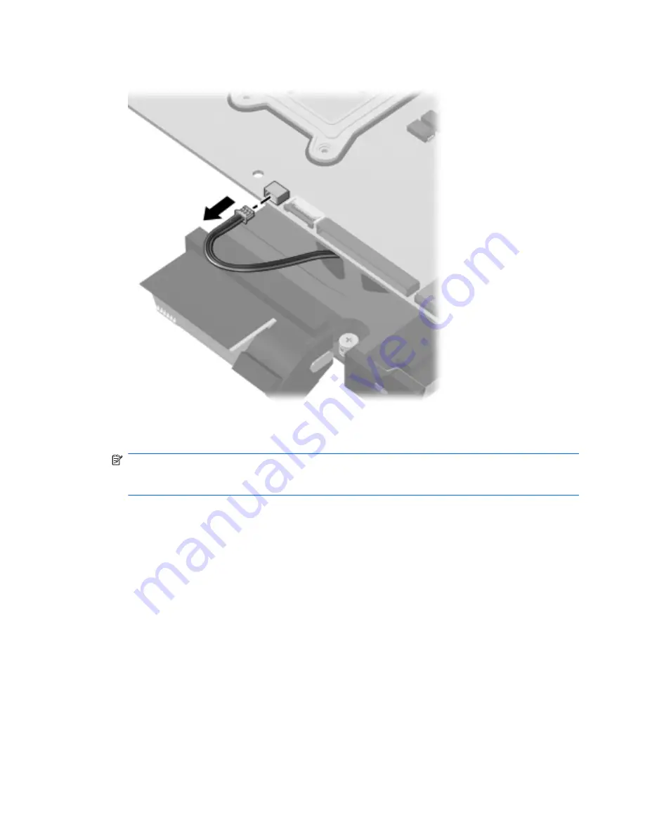
Disconnect the fan cable from the system board.

6.

Follow the sequence embossed on heat sink to loosen the four Phillips PM2.5×7.0 captive screws

(1)

 that secure the fan/heat sink assembly to the system board.

NOTE:

Due to the adhesive quality of the thermal material located between the fan/heat sink

assembly and system board components, it may be necessary to move the fan/heat sink assembly
from side to side to detach the assembly.

88

Chapter 4   Removal and replacement procedures

Содержание Pavilion dm4

Страница 1: ...HP Pavilion dm4 Entertainment PC Maintenance and Service Guide ...

Страница 2: ...on in the United States and other countries Microsoft and Windows are either trademarks or registered trademarks of Microsoft Corporation in the United States and or other countries SD Logo is a trademark of its proprietor The information contained herein is subject to change without notice The only warranties for HP products and services are set forth in the express warranty statements accompanyi...

Страница 3: ...mputer major components on page 19 Sequential part number listing on page 31 WLAN module on page 50 Updated hard drive specifications in the following location Hard drive specifications on page 99 B November 2010 Added newly supported processors to spare parts listings in the following locations Computer major components on page 19 Sequential part number listing on page 31 and Processor on page 90...

Страница 4: ...iv MSG revision history ...

Страница 5: ...allow another hard surface such as an adjoining optional printer or a soft surface such as pillows or rugs or clothing to block airflow Also do not allow the AC adapter to contact the skin or a soft surface such as pillows or rugs or clothing during operation The computer and the AC adapter comply with the user accessible surface temperature limits defined by the International Standard for Safety ...

Страница 6: ...vi Safety warning notice ...

Страница 7: ...14 Bottom components 15 Wireless antennas 16 Additional hardware components 17 3 Illustrated parts catalog 18 Serial number location 18 Computer major components 19 Display assembly components 27 Plastics Kit 28 Mass storage devices 29 Miscellaneous parts 30 Sequential part number listing 31 4 Removal and replacement procedures 38 Preliminary replacement requirements 38 Tools required 38 Service c...

Страница 8: ...print reader board 67 Power button board 69 Display assembly 70 USB board 76 Power connector cable 77 Bluetooth module 79 Speaker assembly 81 System board 83 Fan heat sink assembly 85 Processor 90 5 Setup Utility 92 Starting Setup Utility 92 Using Setup Utility 92 Changing the language of Setup Utility 92 Navigating and selecting in Setup Utility 93 Displaying system information 93 Restoring defau...

Страница 9: ...create restore points 105 Create a system restore point 105 Restore to a previous date and time 106 Performing a recovery 106 Recovering from the recovery discs 106 Recovering from the dedicated recovery partition select models only 106 8 Connector pin assignments 108 Audio out headphone 108 Audio in microphone 108 External monitor 109 RJ 45 network 110 HDMI 111 Universal Serial Bus 112 9 Power co...

Страница 10: ...x ...

Страница 11: ...C turbo up to 3 2 GHz 3 MB L3 cache 540M 2 53 GHz SC turbo up to 3 06 GHz 3 MB L3 cache 520M 2 40 GHz SC turbo up to 2 93 GHz 3 MB L3 cache 480M 2 66 GHz 3 MB L3 cache 460M 2 53 GHz 3 MB L3 cache 450M 2 40 GHz 3 MB L3 cache 430M 2 26 GHz SC turbo to 2 53 GHz 3 MB L3 cache Chipset Intel HM55 Express Graphics Switchable discrete graphics ATi Park Pro ATI Mobility Radeon HD5450 with 512 MB of dedicat...

Страница 12: ...ory DDR3 1333 MHz downgraded to DDR3 1066 MHz Supports the following configurations 8 GB 4 GB 2 6 GB 2 GB 2 4 GB 1 4 MB 2 GB 2 or 4 GBx1 3 GB 1 GB 1 2 GB 1 2 GB 2 GB 1 2 MB 1 GB 2 1 GB 1 GB 1 Hard drives Accelerometer protection support Supports the following 9 5 mm 6 35 cm 2 5 in SATA hard drives 750 GB 7200 and 5400 rpm 640 GB 7200 and 5400 rpm 500 GB 7200 rpm 320 GB 7200 rpm 250 GB 7200 rpm 160...

Страница 13: ...ino Advanced N WiMAX 6250 Broadcom 43224AGN 802 11a b g draft n WiFi Adapter Broadcom 4313AGN 802 11a b g draft n WiFi Adapter Broadcom 4313 802 11b g n 1x1 WiFi and 2070 Bluetooth 2 1 EDR Combo Adapter Realink RT3090BC4 802 11b g n 1x1 WiFi and Bluetooth 2 1 EDR Combo Adapter Integrated WWAN and GPS function Qualcomm module with two antennas 5 band antenna support 2100 1800 1900 800 900 with addi...

Страница 14: ...fault Power requirements 9 cell 93 Wh 2 80 Ah Li ion battery 6 cell 62 Wh 2 80 Ah Li ion battery 6 cell 55 Wh 2 55 Ah Li ion battery 65 W AC adapter with Smart Pin DC connector 90 W AC adapter with Smart Pin DC connector Security Kensington Security Lock Fingerprint reader with Digital Persona Software Support Operating system Preinstalled Windows 7 Professional 64 bit Windows 7 Home Premium 64 bi...

Страница 15: ...Mini card device SIM 5 ...

Страница 16: ...andard features on most computer models To see a list of hardware installed in the computer follow these steps 1 Select Start My Computer 2 In the left pane of the System Tasks window select View system information 3 Select Hardware tab Device Manager You can also add hardware or modify computer configurations using Device Manager 6 Chapter 2 External component identification ...

Страница 17: ...elects or activates items on the screen 3 Left TouchPad button Functions like the left button on an external mouse 4 Right TouchPad button Functions like the right button on an external mouse This table describes factory settings To view or change pointing device preferences select Start Devices and Printers Then right click the icon representing your device and select Mouse settings Top component...

Страница 18: ...ess light White An integrated wireless device such as a wireless local area network WLAN device and or a Bluetooth device is on NOTE Wireless devices are enabled at the factory Amber All wireless devices are off 4 Caps lock light White Caps lock is on 5 TouchPad light Amber TouchPad is disabled 6 Fingerprint reader light White Fingerprint read is good Amber Fingerprint read is bad 8 Chapter 2 Exte...

Страница 19: ... briefly to exit Hibernation If the computer has stopped responding and Windows shutdown procedures are ineffective press and hold the power button for at least 5 seconds to turn off the computer To learn more about your power settings select Start Control Panel System and Security Power Options 2 Fingerprint reader Allows a fingerprint logon to Windows instead of a password logon This table descr...

Страница 20: ... 2 fn key Displays system information when pressed in combination with the esc key 3 Windows logo key Displays the Windows Start menu 4 Windows applications key Displays a shortcut menu for items beneath the pointer 5 Action keys Execute frequently used functions 10 Chapter 2 External component identification ...

Страница 21: ...igital SD Memory Card Secure Digital High Capacity SDHC Memory Card standard and large size xD Picture Card XD 2 Speakers 2 Produce sound Right side components Component Description 1 Optical drive light On The optical drive is being accessed Off The optical drive is idle 2 Optical drive Reads writes optical discs 3 USB ports 2 Connect optional USB devices Front components 11 ...

Страница 22: ...rity cable to the computer NOTE The security cable is designed to act as a deterrent but it may not prevent the computer from being mishandled or stolen 2 External monitor port Connects an optional external display such as a monitor or projector to the computer 3 Audio in microphone jack Connects an optional computer headset microphone stereo array microphone or monaural microphone 4 Audio out hea...

Страница 23: ...l internal components and prevent overheating It is normal for the internal fan to cycle on and off during routine operation 8 RJ 45 network lights White The network is connected Amber The network is showing activity 9 RJ 45 network jack Connects a network cable 10 HDMI port Connects an optional HDMI device 11 Combo eSATA USB port Connects an optional USB device or high performance eSATA component...

Страница 24: ...lay switch Turns off the display if the display is closed while the power is on 2 Webcam light White The webcam is in use 3 Webcam Records video and captures still photographs 4 Internal microphone Record sound 14 Chapter 2 External component identification ...

Страница 25: ...peration 4 Hard drive bay Holds the hard drive 5 Memory Wireless module compartment Holds a wireless LAN module a wireless WAN module and memory modules NOTE To prevent an unresponsive system replace the wireless module only with a wireless module authorized for use in the computer by the governmental agency that regulates wireless devices in your country or region If you replace the module and th...

Страница 26: ...ks WLANs 2 WWAN antennas 2 Send and receive wireless signals to communicate with wireless wide area networks WWANs The antennas are not visible from the outside of the computer For optimal transmission keep the areas immediately around the antennas free from obstructions To see wireless regulatory notices refer to the section of the Regulatory Safety and Environmental Notices that applies to your ...

Страница 27: ... Connects an AC adapter to an AC outlet 2 AC adapter Converts AC power to DC power 3 Battery Powers the computer when the computer is not plugged into external power Batteries and power cords vary in appearance by region and country Additional hardware components 17 ...

Страница 28: ...ic identifier that is unique to each product Part number Product number p n 3 This number provides specific information about the product s hardware components The part number helps a service technician to determine what components and parts are needed Warranty period 4 This number describes the duration in years of the warranty period for the computer Model description 5 This is the alphanumeric ...

Страница 29: ...Computer major components Computer major components 19 ...

Страница 30: ... For use in Saudi Arabia 608022 171 For use in South Korea 608222 AD1 For use in Spain 608022 071 For use in Switzerland 608022 BG1 For use in Taiwan 608222 AB1 For use in Thailand 608222 281 For use in Turkey 608022 141 For use in the United Kingdom 608022 031 For use in the United States 608222 001 3 Top cover includes Touchpad 608224 001 4 Power button board includes cable 608226 001 5 Fingerpr...

Страница 31: ...GHz SC turbo up to 3 33 GHz 3 MB L3 cache 625825 001 560M 2 66 GHz SC turbo up to 3 2 GHz 3 MB L3 cache 625824 001 540M 2 53 GHz SC turbo up to 3 06 GHz 3 MB L3 cache 594188 001 520M 2 40 GHz SC turbo up to 2 93 GHz 3 MB L3 cache 594187 001 480M 2 66 GHz 3 MB L3 cache 634693 001 460M 2 53 GHz 3 MB L3 cache 626039 001 450M 2 40 GHz 3 MB L3 cache 613585 001 430M 2 26 GHz 3 MB L3 cache 597624 001 11 ...

Страница 32: ...adines Suriname Swaziland Sweden Switzerland Syria Taiwan Tajikistan Tanzania Thailand Togo Tonga Trinidad and Tobago Tunisia Turkey Turkmenistan Tuvalu Uganda United Arab Emirates United Kingdom Uruguay Uzbekistan Vanuatu Venezuela Vietnam Yemen Zaire Zambia and Zimbabwe 580101 002 Intel Centrino Wireless N 1000 802 11b g n 1x2 For use in Andorra Antigua and Barbuda Argentina Aruba Australia Aust...

Страница 33: ...Adapter For use in Afghanistan Albania Algeria Andorra Angola Antigua and Barbuda Argentina Armenia Aruba Australia Austria Azerbaijan Bahamas Bahrain Bangladesh Barbados Belarus Belgium Belize Benin Bermuda Bhutan Bolivia Bosnia and Herzegovina Botswana Brazil the British Virgin Islands Brunei Bulgaria Burkina Faso Burundi Cambodia Cameroon Canada Cape Verde the Cayman Islands Central African Rep...

Страница 34: ...y Coast Jamaica Japan Jordan Kazakhstan Kenya Kiribati Kuwait Kyrgyzstan Laos Latvia Lebanon Lesotho Liberia Liechtenstein Lithuania Luxembourg Macedonia Madagascar Malawi Malaysia Maldives Mali Malta Marshall Islands Martinique Mauritania Mauritius Mexico Micronesia Monaco Mongolia Montenegro Morocco Mozambique Namibia Nauru Nepal the Nether Antilles the Netherlands New Zealand Nicaragua Niger Ni...

Страница 35: ...ether Antilles the Netherlands New Zealand Nicaragua Niger Nigeria Norway Oman Pakistan Palau Panama Papua New Guinea Paraguay Peru the Philippines Poland Portugal Puerto Rico the Republic of Moldova Romania Russia Rwanda Samoa San Marino Sao Tome and Principe Saudi Arabia Senegal Serbia and Montenegro Seychelles Sierra Leone Singapore Slovakia Slovenia the Solomon Islands Somalia South Africa Sou...

Страница 36: ...00 RPM replaced by 603785 001 608219 001 640 GB 7200 RPM 621046 001 500 GB 7200 RPM 608218 001 320 GB 7200 RPM 608217 001 250 GB 7200 RPM 608216 001 160 GB solid state drive 608215 001 19 DVD RW SuperMulti DL Drive 12 7 mm optical drive fixed 608221 001 26 Chapter 3 Illustrated parts catalog ...

Страница 37: ...mber 1 Display bezel 608209 001 2 Webcam module 615744 001 3 Display panel Brightview high definition 35 56 cm 14 0 in includes display panel cable For use in models without WWAN 608206 001 For use in models with WWAN 613666 001 Display assembly components 27 ...

Страница 38: ...Kit not illustrated includes screws and screw covers 608212 001 Display cable kit not illustrated 608211 001 Display cable kit for models equipped with WWAN not illustrated 630284 001 Plastics Kit Item Description Spare part number Plastics kit 608233 001 1 Wireless memory module mini card compartment cover includes captive screw 2 Hard drive bay cover includes captive screws 28 Chapter 3 Illustra...

Страница 39: ...le Kit spare part number 608227 001 750 GB 5400 RPM replaces 622394 001 603787 001 750 GB 5400 RPM replaced by 603787 001 622394 001 750 GB 7200 RPM 633252 001 640 GB 7200 RPM 621046 001 640 GB 5400 RPM replaces 608219 001 603785 001 640 GB 5400 RPM replaced by 603785 001 608219 001 500 GB 7200 RPM 608218 001 320 GB 7200 RPM 608217 001 250 GB 7200 RPM 608216 001 160 GB solid state drive 608215 001...

Страница 40: ... For use in Australia 490371 011 For use in Brazil 490371 202 For use in the People s Republic of China 490371 AA1 For use in Denmark 490371 081 For use in Europe the Middle East and Africa 490371 021 For use in India 490371 D61 For use in Italy 490371 061 For use in Japan 490371 291 For use in North America 490371 001 For use in South Korea 490371 AD1 For use in Switzerland 490371 111 For use in ...

Страница 41: ...dom and Singapore 490371 061 Power cord AC 3 pin black 1 83 m for use in Italy 490371 081 Power cord AC 3 pin black 1 83 m for use in Demmark 490371 111 Power cord AC 3 pin black 1 83 m for use in Switzerland 490371 201 Power cord AC 3 pin black 1 83 m for use in Thailand 490371 202 Power cord AC 3 pin black 1 83 m for use in Brazil 490371 291 Power cord AC 3 pin black 1 83 m for use in Japan 4903...

Страница 42: ...Vietnam Yemen Zaire Zambia and Zimbabwe 582564 001 Broadcom 43224AGN 802 11a b g draft n WiFi Adapter for use in Antigua and Barbuda Aruba the Bahamas Barbados Belize Canada Guam Guinea Haiti Jamaica the Nether Antilles Puerto Rico St Kitts and Nevis St Lucia St Vincent and the Grenadines Suriname the US Virgin Islands and the United States 582564 002 Broadcom 43224AGN 802 11a b g draft n WiFi Ada...

Страница 43: ...eople s Republic of China Colombia Comoros Congo Costa Rica Croatia Cyprus the Czech Republic Denmark Djibouti Dominica the Dominican Republic East Timor Ecuador Egypt El Salvador Equitorial Guinea Eritrea Estonia Ethiopia Fiji Finland France French Guiana Gabon Gambia Georgia Germany Ghana Gibraltar Greece Grenada Guadeloupe Guam Guatemala Guinea Guinea Bissa Guyana Haiti Honduras Hong Kong Hunga...

Страница 44: ... Adapter for use in Afghanistan Albania Algeria Andorra Angola Antigua and Barbuda Argentina Armenia Aruba Australia Austria Azerbaijan Bahamas Bahrain Barbados Belarus Belgium Belize Benin Bermuda Bhutan Bolivia Bosnia and Herzegovina Botswana Brazil British Virgin Islands Brunei Bulgaria Burkina Faso Burundi Cambodia Cameroon Canada Cape Verde the Cayman Islands Central African Republic Chad Chi...

Страница 45: ...D RW SuperMulti DL Drive 608222 001 Keyboard for use in the United States 608222 031 Keyboard for use in the United Kingdom 608222 041 Keyboard for use in Germany 608222 051 Keyboard for use in France 608222 071 Keyboard for use in Spain 608222 121 Keyboard for use in English and French Canada 608222 141 Keyboard for use in Turkey 608222 161 Keyboard for use in Latin America 608222 171 Keyboard fo...

Страница 46: ...5 450M Dual Core processor 2 40 GHz 3 MB L3 cache 613666 001 35 56 cm 14 0 in display panel high definition BrightView for use in models with WWAN 613667 001 35 56 cm 14 0 in WXGA Brightview display assembly for use in models equipped with WWAN 615744 001 Webcam module 616244 001 System board includes replacement thermal material for use in models with 1 GB of HD5450 discrete graphics memory 61999...

Страница 47: ...rete graphics memory 630714 001 System board for use in models equipped with 1 GB of HD6370 discrete graphics memory 633252 001 750 GB 7200 RPM hard drive 633863 001 System board for use in models equipped with WiMAX and UMA graphics 634336 001 Thermal pad kit 634693 001 Intel Core i5 480M Dual Core processor 2 66 GHz 3 MB L3 cache Sequential part number listing 37 ...

Страница 48: ...e some of the considerations that you must keep in mind during disassembly and assembly procedures NOTE As you remove each subassembly from the computer place the subassembly and all accompanying screws away from the work area to prevent damage Plastic parts Using excessive force during disassembly and reassembly can damage plastic parts Use care when handling the plastic parts Apply pressure only...

Страница 49: ... inserting a hard drive shut down the computer If you are unsure whether the computer is off or in Hibernation turn the computer on and then shut it down through the operating system Before handling a drive be sure that you are discharged of static electricity While handling a drive avoid touching the connector Before removing a diskette drive or optical drive be sure that a diskette or disc is no...

Страница 50: ...ep components in their electrostatic safe containers until you are ready to install them Use nonmagnetic tools Before touching an electronic component discharge static electricity by using the guidelines described in this section Avoid touching pins leads and circuitry Handle electronic components as little as possible If you remove a component place it in an electrostatic safe container The follo...

Страница 51: ...nd and that proper materials are selected to avoid static charging When grounding is not possible use an ionizer to dissipate electric charges Workstation guidelines Follow these grounding workstation guidelines Cover the workstation with approved static shielding material Use a wrist strap connected to a properly grounded work surface and use properly grounded tools and equipment Use conductive f...

Страница 52: ...tween the operator and ground To be effective the conductive strips must be worn in contact with the skin The following grounding equipment is recommended to prevent electrostatic damage Antistatic tape Antistatic smocks aprons and sleeve protectors Conductive bins and other assembly or soldering aids Nonconductive foam Conductive tabletop workstations with ground cords of one megohm resistance St...

Страница 53: ...echnical support Product name 1 This is the product name affixed to the front of the computer Serial number s n 2 This is an alphanumeric identifier that is unique to each product Part number Product number p n 3 This number provides specific information about the product s hardware components The part number helps a service technician to determine what components and parts are needed Warranty per...

Страница 54: ...ption Spare part number Rubber Feet Kit 608228 001 The computer feet are adhesive backed rubber pads The feet attach to the base enclosure in the locations illustrated below 44 Chapter 4 Removal and replacement procedures ...

Страница 55: ...nected to the computer 3 Disconnect the power from the computer by first unplugging the power cord from the AC outlet and then unplugging the AC adapter from the computer Remove the battery 1 Turn the computer upside down on a flat surface 2 Slide the battery release latch 1 to release the battery 3 Pivot the battery 2 upward and lift it out of the computer 3 To insert the battery insert the rear ...

Страница 56: ...r is off or in Hibernation turn the computer on and then shut it down through the operating system 2 Disconnect all external devices connected to the computer 3 Disconnect the power from the computer by first unplugging the power cord from the AC outlet and then unplugging the AC adapter from the computer 4 Remove the battery see Battery on page 45 Remove the SIM 1 Press in on the SIM 1 The module...

Страница 57: ...r cord from the AC outlet and then unplugging the AC adapter from the computer 4 Remove the battery see Battery on page 45 Remove the memory module 1 Turn the computer upside down with the front toward you 2 Loosen the two Phillips PM2 5 5 0 captive screws 1 that secure the memory wireless module compartment cover to the computer 3 Lift the left side of the cover 2 swing it forward and remove it 3...

Страница 58: ... away from the slot at an angle NOTE Memory modules are designed with a notch 3 to prevent incorrect insertion into the memory module slot Reverse this procedure to install a memory module 48 Chapter 4 Removal and replacement procedures ...

Страница 59: ...devices connected to the computer 3 Disconnect the power from the computer by first unplugging the power cord from the AC outlet and then unplugging the AC adapter from the computer 4 Remove the battery see Battery on page 45 5 Hard drive cover see Hard drive on page 57 Remove the RTC battery 1 Turn the system board upside down 2 Release the RTC battery from the clips on the system board 1 3 Remov...

Страница 60: ...olomon Islands Somalia South Africa South Korea Spain Sri Lanka St Kitts and Nevis St Lucia St Vincent and the Grenadines Suriname Swaziland Sweden Switzerland Syria Taiwan Tajikistan Tanzania Thailand Togo Tonga Trinidad and Tobago Tunisia Turkey Turkmenistan Tuvalu Uganda United Arab Emirates United Kingdom Uruguay Uzbekistan Vanuatu Venezuela Vietnam Yemen Zaire Zambia and Zimbabwe 580101 002 I...

Страница 61: ...r For use in Afghanistan Albania Algeria Andorra Angola Antigua and Barbuda Argentina Armenia Aruba Australia Austria Azerbaijan Bahamas Bahrain Bangladesh Barbados Belarus Belgium Belize Benin Bermuda Bhutan Bolivia Bosnia and Herzegovina Botswana Brazil the British Virgin Islands Brunei Bulgaria Burkina Faso Burundi Cambodia Cameroon Canada Cape Verde the Cayman Islands Central African Republic ...

Страница 62: ...am Yemen Zaire Zambia and Zimbabwe 602992 001 Broadcom 4313 802 11b g n 1x1 WiFi and 2070 Bluetooth 2 1 EDR Combo Adapter For use in Afghanistan Albania Algeria Andorra Angola Antigua and Barbuda Argentina Armenia Aruba Australia Austria Azerbaijan Bahamas Bahrain Bangladesh Barbados Belarus Belgium Belize Benin Bermuda Bhutan Bolivia Bosnia and Herzegovina Botswana Brazil the British Virgin Islan...

Страница 63: ... cord from the AC outlet and then unplugging the AC adapter from the computer 4 Remove the battery see Battery on page 45 5 Remove the memory wireless module compartment cover see Memory module on page 47 Remove the WLAN module 1 Turn the computer upside down with the front toward you 2 Disconnect the two WLAN antenna cables 1 from the WLAN module 3 Remove the two Phillips PM2 0 4 0 screws 2 that ...

Страница 64: ...y that regulates wireless devices in your country or region If you replace the module and then receive a warning message remove the module to restore computer functionality and then contact technical support through Help and Support NOTE WLAN modules are designed with a notch 4 to prevent incorrect insertion into the WLAN module slot Reverse this procedure to install a WLAN module 54 Chapter 4 Rem...

Страница 65: ...mputer 3 Disconnect the power from the computer by first unplugging the power cord from the AC outlet and then unplugging the AC adapter from the computer 4 Remove the battery see Battery on page 45 5 Remove the memory wireless module compartment cover see Memory module on page 47 Remove the WWAN module 1 Turn the computer upright with the front toward you 2 Disconnect the two WWAN antenna cables ...

Страница 66: ...it away from the slot at an angle NOTE WWAN modules are designed with a notch 4 to prevent incorrect insertion into the WWAN module slot Reverse the above procedure to install the WWAN module 56 Chapter 4 Removal and replacement procedures ...

Страница 67: ...01 Before removing the hard drive follow these steps 1 Shut down the computer If you are unsure whether the computer is off or in Hibernation turn the computer on and then shut it down through the operating system 2 Disconnect all external devices connected to the computer 3 Disconnect the power from the computer by first unplugging the power cord from the AC outlet and then unplugging the AC adap...

Страница 68: ...number 608233 001 4 Disconnect the hard drive cable from the system board 1 5 Lift the hard drive out of the hard drive bay 2 6 If it is necessary to replace the hard drive bracket also called the protective cover disconnect the hard drive cable 1 from the hard drive 58 Chapter 4 Removal and replacement procedures ...

Страница 69: ...ur Phillips PM3 0 3 0 screws 2 and cover 3 only If the hard drive does not already have these components preassembled Reverse this procedure to reassemble and install the hard drive Component replacement procedures 59 ...

Страница 70: ...ve the battery see Battery on page 45 5 Remove the memory wireless module compartment cover see Memory module on page 47 6 Remove the hard drive cover see Hard drive on page 57 Remove the optical drive 1 Position the computer upside down with the front toward you 2 Remove the Phillips PM2 5x5 0 screw 1 that secures the optical drive to the computer 3 Use a flat bladed screwdriver or similar tool t...

Страница 71: ... 2 and remove the bezel 3 8 If it is necessary to replace the optical drive bracket position the optical drive with the optical drive bracket toward you 9 Remove the two Phillips PM2 0 3 0 screws 1 that secure the optical drive bracket to the optical drive 10 Remove the optical drive bracket 2 Component replacement procedures 61 ...

Страница 72: ...d 608222 BG1 Keyboard for use in Taiwan 608222 AB1 Keyboard for use in Thailand 608222 281 Keyboard for use in Turkey 608222 141 Keyboard for use in the United Kingdom 608222 031 Keyboard for use in the United States 608222 001 Before removing the keyboard follow these steps 1 Shut down the computer If you are unsure whether the computer is off or in Hibernation turn the computer on and then shut ...

Страница 73: ...s far as possible 5 Release the top edge of the keyboard by lifting it up to disengage the keyboard from the tabs on the top cover 1 6 Rotate the keyboard over until it rests on the palm rest 2 7 Release the zero insertion force ZIF connector to which the keyboard cable is attached and disconnect the keyboard cable 3 from the system board 8 Remove the keyboard Reverse this procedure to install the...

Страница 74: ...er from the computer by first unplugging the power cord from the AC outlet and then unplugging the AC adapter from the computer 4 Remove the following components a Battery see Battery on page 45 b Hard drive see Hard drive on page 57 c Optical drive see Optical drive on page 60 d Keyboard see Keyboard on page 62 Remove the top cover 1 Turn the computer upside down with the front toward you 2 Remov...

Страница 75: ... far as possible 6 Remove the four Phillips PM2 0 4 0 screws that secure the top cover to the base enclosure and then disengage the top cover from the base enclosure and lift the top cover up enough to gain access to the cables 7 Release the ZIF connector to which the power button board is connected and disconnect the cable from the system board 1 Component replacement procedures 65 ...

Страница 76: ...ble from the system board 2 9 Release the ZIF connector to which the fingerprint reader board cable is connected and disconnect the cable from the system board 3 10 Remove the top cover from the base enclosure Reverse this procedure to install the top cover 66 Chapter 4 Removal and replacement procedures ...

Страница 77: ...gging the AC adapter from the computer 4 Remove the battery see Battery on page 45 5 Remove the following components a Hard drive see Hard drive on page 57 b Optical drive see Optical drive on page 60 c Keyboard see Keyboard on page 62 d Top cover see Top cover on page 64 Remove the fingerprint reader board 1 Turn the top cover upside down with the front toward you 2 Remove the Phillips PM2 0 3 0 ...

Страница 78: ...e the above procedure to install the fingerprint reader board NOTE To reinstall place the board into the slot and then place the bracket over it by setting the right side of bracket into the slots Then replace the screw 68 Chapter 4 Removal and replacement procedures ...

Страница 79: ...irst unplugging the power cord from the AC outlet and then unplugging the AC adapter from the computer 4 Remove the battery see Battery on page 45 5 Remove the following components a Hard drive see Hard drive on page 57 b Optical drive see Optical drive on page 60 c Keyboard see Keyboard on page 62 d Top cover see Top cover on page 64 Reverse this procedure to install the power button board Remove...

Страница 80: ... the computer is off or in Hibernation turn the computer on and then shut it down through the operating system 2 Disconnect all external devices connected to the computer 3 Disconnect the power from the computer by first unplugging the power cord from the AC outlet and then unplugging the AC adapter from the computer 4 Remove the battery see Battery on page 45 5 Disconnect the wireless antenna cab...

Страница 81: ...mbly to the computer CAUTION Support the display assembly when removing the display screws in the following steps Failure to support the display assembly can result in damage to the assembly and other components 5 Remove the wireless antenna cables from the hole 3 built into the base enclosure 6 Remove the display assembly 4 NOTE In the left main display hinge screws populate the right and left ho...

Страница 82: ...omponents remove the following screw covers and screws The display screw covers are included in the Display Screw Kit spare part number 608212 001 1 Two Mylar screw covers on the display bezel bottom edge 2 Two Phillips PM2 5 5 0 screws 9 Flex the inside edge of the top 1 the left and right sides 2 and the bottom 3 of the display bezel until the bezel disengages from the display back cover 72 Chap...

Страница 83: ...rom the double sided tape on the display back cover 1 disconnect the webcam cable 2 from the module and remove the webcam The webcam is available using spare part number 615744 001 12 If it is necessary to replace the display panel remove the four Phillips PM2 0 5 0 screws 1 that secure the display panel to the display enclosure Component replacement procedures 73 ...

Страница 84: ... for models with WWAN NOTE The hinge cover screws are thicker than the other screws 14 If it is necessary to replace the display cable follow these steps a Turn the display panel upside down in front of you b Disengage the webcam cable from the glue securing it to the back of the display 1 c Peel back the tape that secures the display cable to the display 2 d Unplug the display cable from the disp...

Страница 85: ...ng path through the right hinge 3 NOTE The silver screws go on the outside of the hinges 17 If it is necessary to replace the wireless antennas and cables remove the adhesive strip 1 that secures each antenna to the display back cover 18 Remove the antennas from the clips 2 built into the top of the display enclosure 19 Remove the wireless antennas and cables 3 from the display enclosure The wirel...

Страница 86: ...ging the power cord from the AC outlet and then unplugging the AC adapter from the computer 4 Remove the battery see Battery on page 45 5 Remove the following components a Hard drive see Hard drive on page 57 b Optical drive see Optical drive on page 60 c Keyboard see Keyboard on page 62 d Top cover see Top cover on page 64 Remove the USB board 1 Position the computer upright with the right side t...

Страница 87: ...ter If you are unsure whether the computer is off or in Hibernation turn the computer on and then shut it down through the operating system 2 Disconnect all external devices connected to the computer 3 Disconnect the power from the computer by first unplugging the power cord from the AC outlet and then unplugging the AC adapter from the computer 4 Remove the battery see Battery on page 45 5 Remove...

Страница 88: ... Disconnect the power connector cable 1 from the system board 3 Remove the two Phillips PM2 5 5 0 screws 2 that secure the power connector cable to the base enclosure 4 Lift the bracket from the connector 3 5 Remove the power connector 4 from the base enclosure Reverse this procedure to install the power connector cable 78 Chapter 4 Removal and replacement procedures ...

Страница 89: ...onnect the power from the computer by first unplugging the power cord from the AC outlet and then unplugging the AC adapter from the computer 4 Remove the battery see Battery on page 45 5 Remove the following components a Hard drive see Hard drive on page 57 b Optical drive see Optical drive on page 60 c Keyboard see Keyboard on page 62 d Top cover see Top cover on page 64 Remove the Bluetooth mod...

Страница 90: ...oth module and cable from the slot in the base enclosure 3 while noting the cable routing path atop the speaker 4 Reverse the above procedure to install the Bluetooth module 80 Chapter 4 Removal and replacement procedures ...

Страница 91: ...ging the power cord from the AC outlet and then unplugging the AC adapter from the computer 4 Remove the battery see Battery on page 45 5 Remove the following components a Optical drive see Optical drive on page 60 b Keyboard see Keyboard on page 62 c Top cover see Top cover on page 64 d Bluetooth module see Bluetooth module on page 79 Remove the speaker assembly 1 Position the computer upright wi...

Страница 92: ...4 Lift the speaker assembly straight up 3 to remove it from the base enclosure Reverse this procedure to install the speaker assembly 82 Chapter 4 Removal and replacement procedures ...

Страница 93: ...lowing components are removed from the defective system board and installed on the replacement system board SIM see SIM on page 46 RTC battery see RTC battery on page 49 Memory modules see Memory module on page 47 WLAN module see WLAN module on page 50 WWAN module see WWAN module on page 55 Fan heat sink assembly see Fan heat sink assembly on page 85 Processor see Processor on page 90 Before remov...

Страница 94: ...pright with the left side toward you 2 Remove the three Phillips PM2 5 5 0 screws 1 that secure the system board to the computer 3 Loosen the captive screw in the fan sink that secures the system board 2 4 Lift the right side of the system board 3 5 Release the system board by sliding it to the right at an angle 4 until the connectors on the left side of the system board clear the base enclosure a...

Страница 95: ...ng the fan heat sink assembly follow these steps 1 Shut down the computer If you are unsure whether the computer is off or in Hibernation turn the computer on and then shut it down through the operating system 2 Disconnect all external devices connected to the computer 3 Disconnect the power from the computer by first unplugging the power cord from the AC outlet and then unplugging the AC adapter ...

Страница 96: ... board 3 Follow the sequence embossed on heat sink to loosen the six Phillips PM2 5 7 0 captive screws 1 that secure the fan heat sink assembly to the system board NOTE Due to the adhesive quality of the thermal material located between the fan heat sink assembly and system board components it may be necessary to move the fan heat sink assembly from side to side to detach the assembly 86 Chapter 4...

Страница 97: ...embly is removed Thermal pads and thermal paste must be installed on all surfaces before the fan heat sink assembly is reinstalled The following illustration shows the locations for thermal material on systems with discrete graphics subsystems NOTE Steps 5 through 7 apply to computers with UMA subsystem memory on the system board Steps 1 through 4 apply to computers with discrete subsystem memory ...

Страница 98: ... screws 1 that secure the fan heat sink assembly to the system board NOTE Due to the adhesive quality of the thermal material located between the fan heat sink assembly and system board components it may be necessary to move the fan heat sink assembly from side to side to detach the assembly 88 Chapter 4 Removal and replacement procedures ...

Страница 99: ...nd thermal paste must be installed on all surfaces before the fan heat sink assembly is reinstalled NOTE Thermal pads and thermal paste are included with all fan heat sink assembly system board and processor spare part kits The following illustration shows the locations for thermal material on systems with UMA graphics subsystems Reverse this procedure to install the fan heat sink assembly Compone...

Страница 100: ... MB L3 cache 613585 001 Intel Core i5 430M Dual Core processor 2 26 GHz 3 MB L3 cache 597624 001 Before removing the processor follow these steps 1 Shut down the computer If you are unsure whether the computer is off or in Hibernation turn the computer on and then shut it down through the operating system 2 Disconnect all external devices connected to the computer 3 Disconnect the power from the c...

Страница 101: ...locking screw 1 one half turn counterclockwise until you hear a click 2 Lift the processor 2 straight up and remove it NOTE The gold triangle 3 on the processor must be aligned with the triangle icon 4 embossed on the processor socket when you install the processor Reverse this procedure to install the processor Component replacement procedures 91 ...

Страница 102: ...er left corner of the screen press esc 2 When the Startup Menu is displayed press f10 Using Setup Utility Changing the language of Setup Utility The following procedure explains how to change the language of Setup Utility If Setup Utility is not already running begin at step 1 If Setup Utility is already running begin at step 2 1 Open Setup Utility by turning on or restarting the computer While th...

Страница 103: ...hile Setup Utility is open press f1 Displaying system information The following procedure explains how to display system information in Setup Utility If Setup Utility is not open begin at step 1 If Setup Utility is open begin at step 2 1 Open Setup Utility by turning on or restarting the computer While the Press the ESC key for Startup Menu message is displayed in the lower left corner of the scre...

Страница 104: ... press enter 4 To save your change and exit Setup Utility use the arrow keys to select Exit Exit Saving Changes and then press enter The Setup Utility default settings go into effect when the computer restarts NOTE Your password security and language settings are not changed when you restore the factory default settings Exiting Setup Utility You can exit Setup Utility with or without saving change...

Страница 105: ...word Enter change or delete an administrator password Power On Password Enter change or delete a power on password System Configuration menu Select To do this Language Support Change the Setup Utility language Button Sound select models only Enable disable the capacitive button tapping sound Virtualization Technology select models only Enable disable the processor Virtualization Technology Process...

Страница 106: ...apter boot Enable disable boot from Internal Network Adapter Boot Order Set the boot order for Hard drive Internal CD DVD ROM drive USB Diskette on Key USB hard disk USB CD DVD ROM drive USB floppy Network adapter Diagnostics menu Select To do this Hard Disk Self Test Run a comprehensive self test on the hard drive NOTE On models with two hard drives this menu option is called Primary Hard Disk Se...

Страница 107: ... writing to optical disc 0 C to 35 C 32 F to 95 F Operating writing to optical disc 5 C to 35 C 41 F to 95 F Nonoperating 20 C to 60 C 4 F to 140 F Relative humidity Operating 10 to 90 Nonoperating 5 to 95 Maximum altitude unpressurized Operating 15 m to 3 048 m 50 ft to 10 000 ft Nonoperating 15 m to 12 192 m 50 ft to 40 000 ft NOTE Applicable product safety standards specify thermal limits for p...

Страница 108: ...52 Resolution 1366 768 HD Weight 320 g 0 71 lbs Contrast ratio 500 1 typical Luminance 200 nits typical Luminance uniformity 1 4 typical 1 6 max Lifetime 1 2 luminance 12 000 hours Backlight LED Response time 8 ms typical Surface treatment BV Total power consumption 2 8 W Viewing angle SVA 98 Chapter 6 Specifications ...

Страница 109: ...mum 22 0 ms 22 0 ms 22 0 ms 22 0 ms 22 0 ms Logical blocks 1 465 149 1 68 1 250 263 7 28 976 773 168 625 142 448 488 397 168 Disc rotational speed 5400 and 7200 rpm 5400 and 7200 rpm 7200 rpm 7200 rpm 7200 rpm Operating temperature 5 C to 55 C 41 F to 131 F 1 GB 1 billion bytes when referring to hard drive storage capacity Actual accessible capacity is less Actual drive specifications may differ s...

Страница 110: ...18 DVD R DVD RW DVD R DVD RW DVD RAM Write CD R and CD RW DVD R DVD RW DVD R DVD RW DVD RAM Random access time DVD 230 ms CD 175 ms Cache buffer 2 MB Data transfer rate 24X CD ROM 3 600 KB sec 8X DVD ROM 10 800 KB sec 24X CD R 3 600 KB sec 16X CD RW 2 400 KB sec 8X DVD R 10 800 KB sec 4X DVD RW 5 400 KB sec 8X DVD R 10 800 KB sec 4X DVD RW 5 400 KB sec 2 4X DVD R 9 2 700 KB sec 5X DVD RAM 6 750 KB...

Страница 111: ...nge the resource settings in Device Manager to be sure each setting is unique CAUTION Improperly changing resource settings can disable your hardware and cause your computer to malfunction or become inoperable Only users who have expert knowledge of computer hardware and hardware configurations should change resource settings To view resource settings in Windows 7 1 Select Start Computer 2 Click S...

Страница 112: ...rating system feature System restore points allow you to reverse undesirable changes to your computer by restoring the computer to an earlier state Recovering a program or driver Recovery Manager software feature This feature helps you reinstall a program or driver without performing a full system recovery Performing a full system recovery Recovery Manager software feature With Recovery Manager yo...

Страница 113: ... a hub You will need high quality DVD R DVD R BD R writable Blu ray or CD R discs All these discs are purchased separately DVDs and BDs have a much higher capacity than CDs If you use CDs up to 20 discs may be required whereas only a few DVDs or BDs are required NOTE Read write discs such as CD RW DVD RW double layer DVD R and BD RE rewritable Blu ray discs are not compatible with the Recovery Man...

Страница 114: ... shot of your settings The screen shot can be a time saver if you have to reset your preferences To copy the screen and paste it into a word processing document follow these steps 1 Display the screen 2 Copy the screen To copy only the active window press alt prt sc To copy the entire screen press prt sc 3 Open a word processing document and then select Edit Paste 4 Save the document You can back ...

Страница 115: ...ore point allows you to save and name a snapshot of your hard drive at a specific point in time You can then recover back to that point if you want to reverse subsequent changes made to your system NOTE Recovering to an earlier restore point does not affect data files saved or e mails created since the last restore point You also can create additional restore points to provide increased protection...

Страница 116: ...ecovery discs have been included with your computer Use these discs to recover your operating system and software NOTE Windows has its own built in repair features such as System Restore If you have not already tried these features try them before using Recovery Manager NOTE Recovery Manager recovers only software that was preinstalled at the factory Software not provided with this computer must b...

Страница 117: ...ecovery Manager in either of the following ways Select Start All Programs Recovery Manager Recovery Manager or Turn on or restart the computer and then press esc while the Press the ESC key for Startup Menu message is displayed at the bottom of the screen Then press f11 while the Press F11 for recovery message is displayed on the screen 2 Click System Recovery in the Recovery Manager window 3 Foll...

Страница 118: ...assignments Audio out headphone Pin Signal 1 Audio out left channel 2 Audio out right channel 3 Ground Audio in microphone Pin Signal 1 Audio signal in 2 Audio signal in 3 Ground 108 Chapter 8 Connector pin assignments ...

Страница 119: ...d analog 2 Green analog 3 Blue analog 4 Not connected 5 Ground 6 Ground analog 7 Ground analog 8 Ground analog 9 5 VDC 10 Ground 11 Monitor detect 12 DDC 2B data 13 Horizontal sync 14 Vertical sync 15 DDC 2B clock External monitor 109 ...

Страница 120: ...RJ 45 network Pin Signal 1 Transmit 2 Transmit 3 Receive 4 Unused 5 Unused 6 Receive 7 Unused 8 Unused 110 Chapter 8 Connector pin assignments ...

Страница 121: ... data 2 4 TMDS data 1 5 TMDS data 1shield 6 TMDS data 1 7 TMDS data 0 8 TMDS data 0 shield 9 TMDS data 0 10 TMDS clock 11 TMDS clock shield 12 TMDS clock 13 CEC 14 No connect 15 DDC clock 16 DDC data 17 Ground 18 5V power 19 Hot plug detect 20 Shell HDMI 111 ...

Страница 122: ...Universal Serial Bus Pin Signal 1 5 VDC 2 Data 3 Data 4 Ground 112 Chapter 8 Connector pin assignments ...

Страница 123: ...ents listed below are applicable to all countries or regions The length of the power cord set must be at least 1 5 m 5 0 ft and no more than 2 0 m 6 5 ft All power cord sets must be approved by an acceptable accredited agency responsible for evaluation in the country or region where the power cord set will be used The power cord sets must have a minimum current capacity of 10 amps and a nominal vo...

Страница 124: ...g must be a two pole grounding type with a NEMA 5 15P 15 A 125 V or NEMA 6 15P 15 A 250 V configuration 3 The appliance coupler flexible cord and wall plug must bear a T mark and registration number in accordance with the Japanese Dentori Law The flexible cord must be Type VCT or VCTF 3 conductor 1 00 mm conductor size The wall plug must be a two pole grounding type with a Japanese Industrial Stan...

Страница 125: ...handle them carefully NOTE Materials Disposal This HP product contains mercury in the backlight in the display assembly that might require special handling at end of life Disposal of mercury may be regulated because of environmental considerations For disposal or recycling information contact your local authorities or see the Electronic Industries Alliance EIA Web site at http www eiae org This se...

Страница 126: ... 1 and screws 2 that secure the display bezel to the display assembly 2 Lift up and out on the left and right inside edges 1 and the top and bottom inside edges 2 of the display bezel until the bezel disengages from the display assembly 3 Remove the display bezel 3 116 Chapter 10 Recycling ...

Страница 127: ...ssembly to the display enclosure 6 Remove the display panel assembly 2 from the display enclosure 7 Turn the display panel assembly upside down 8 Remove all screws that secure the display panel frame to the display panel 9 Use a sharp edged tool to cut the tape 1 that secures the sides of the display panel to the display panel frame Display 117 ...

Страница 128: ...splay panel 11 Remove the screws 1 that secure the backlight cover to the display panel 12 Lift the top edge of the backlight cover 2 and swing it outward 13 Remove the backlight cover 14 Turn the display panel right side up 118 Chapter 10 Recycling ...

Страница 129: ...l 16 Turn the display panel upside down WARNING The backlight contains mercury Exercise caution when removing and handling the backlight to avoid damaging this component and causing exposure to the mercury 17 Remove the backlight frame from the display panel Display 119 ...

Страница 130: ...CD panel 20 Remove the screws 2 that secure the LCD panel to the display rear panel 21 Release the LCD panel 3 from the display rear panel 22 Release the tape 4 that secures the LCD panel to the display rear panel 23 Remove the LCD panel 24 Recycle the LCD panel and backlight 120 Chapter 10 Recycling ...

Страница 131: ...left TouchPad 7 power 9 right TouchPad 7 TouchPad on off button 7 C cables service considerations 39 camera module removal 73 spare part number 73 camera product description 3 caps lock light identifying 8 Card Reader Power Saving 95 compartments memory module 15 wireless module 15 components additional hardware 17 bottom 15 display 14 front 6 11 left side 12 right side 11 top 7 computer feet loca...

Страница 132: ...ing 9 fn key identifying 10 front components 6 full system recovery 102 G graphics product description 1 grounding equipment and methods 42 H hard drive identifying 15 precautions 39 product description 2 removal 57 spare part numbers 25 29 35 36 57 specifications 99 hard drive cable spare part number 25 29 36 57 hard drive cover illustrated 28 removal 58 hard drive self test 96 HDMI port pin assi...

Страница 133: ...cards 3 graphics 1 hard drives 2 keyboard 4 memory module 2 microphone 3 operating system 4 optical drives 2 pointing devices 4 ports 3 power requirements 4 processors 1 product name 1 security 4 serviceability 4 wireless 3 product name 1 R recovering a program or driver 102 from the dedicated recovery partition 106 from the recovery discs 106 recovery discs 102 103 Recovery Manager 102 106 recove...

Страница 134: ...d removal 76 spare part number 20 36 76 USB ports identifying 11 pin assignments 112 using system restore 105 V vents identifying 15 Virtualization Technology 95 W webcam module removal 73 spare part number 27 36 73 webcam identifying 14 Windows applications key identifying 10 Windows logo key identifying 10 wireless antenna removal 75 wireless antennas 16 wireless antennas and cables removal 75 s...

Страница 135: ......

Отзывы: