


3.
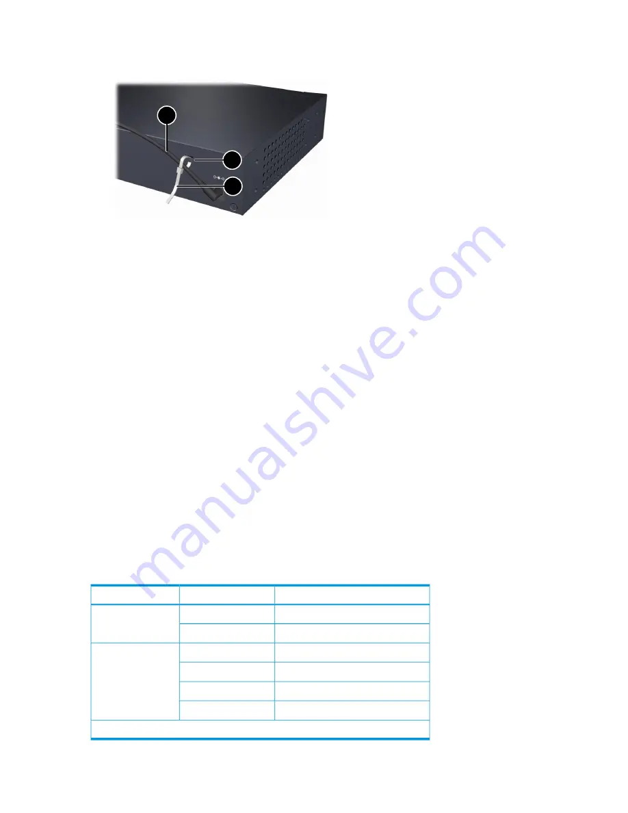
Secure the power cable to the controller with the provided cable tie.
Figure 9 Securing the power cable to the controller
1
2
3
3. Cable tie
2. Cable tie anchor
1. Power cable
Connect the network cables
Connect network cables from the network devices or patch panels to the controller.
Using the RJ-45 connectors
To connect:
Push the RJ-45 plug into the RJ-45 port until the tab on the plug clicks into place. The Link LED lights
when the devices at both ends of the cables are powered on.
To disconnect:
Press the small tab on the plug, and pull the plug out of the port.
Installing or removing optional mini-GBICs
You can install or remove an optional mini-GBIC from a mini-GBIC slot without having to power
off the controller. Use only HP mini-GBICs.
Mini-GBIC information
Dual-personality ports use either the 10/100/1000Base-T RJ-45 connector, or a supported HP
mini-GBIC (Small Form Factor Pluggable (SFP)) for fiber-optic connection. By default, the RJ-45
connectors are enabled.
The optional mini-GBICs add support for these speeds and technologies:
Table 4 Optional network speeds and technologies
Cabling*
Technology
Speed
Fiber (multimode)
100-FX
100 Mbps
Fiber (single mode)
100-BX
Fiber (multimode)
1000-SX
1 Gbps
Fiber (multimode or single mode)
1000-LX
Fiber (single mode)
1000-LH
Fiber (single mode)
1000-BX
*See also
“Cabling and safety standards” (page 21)
.
14
Installing the controller


