


Chapter 4
99
Field Replaceable Units (FRUs)
FRU Removal and Replacement
Removing and Replacing the Real-Time Clock
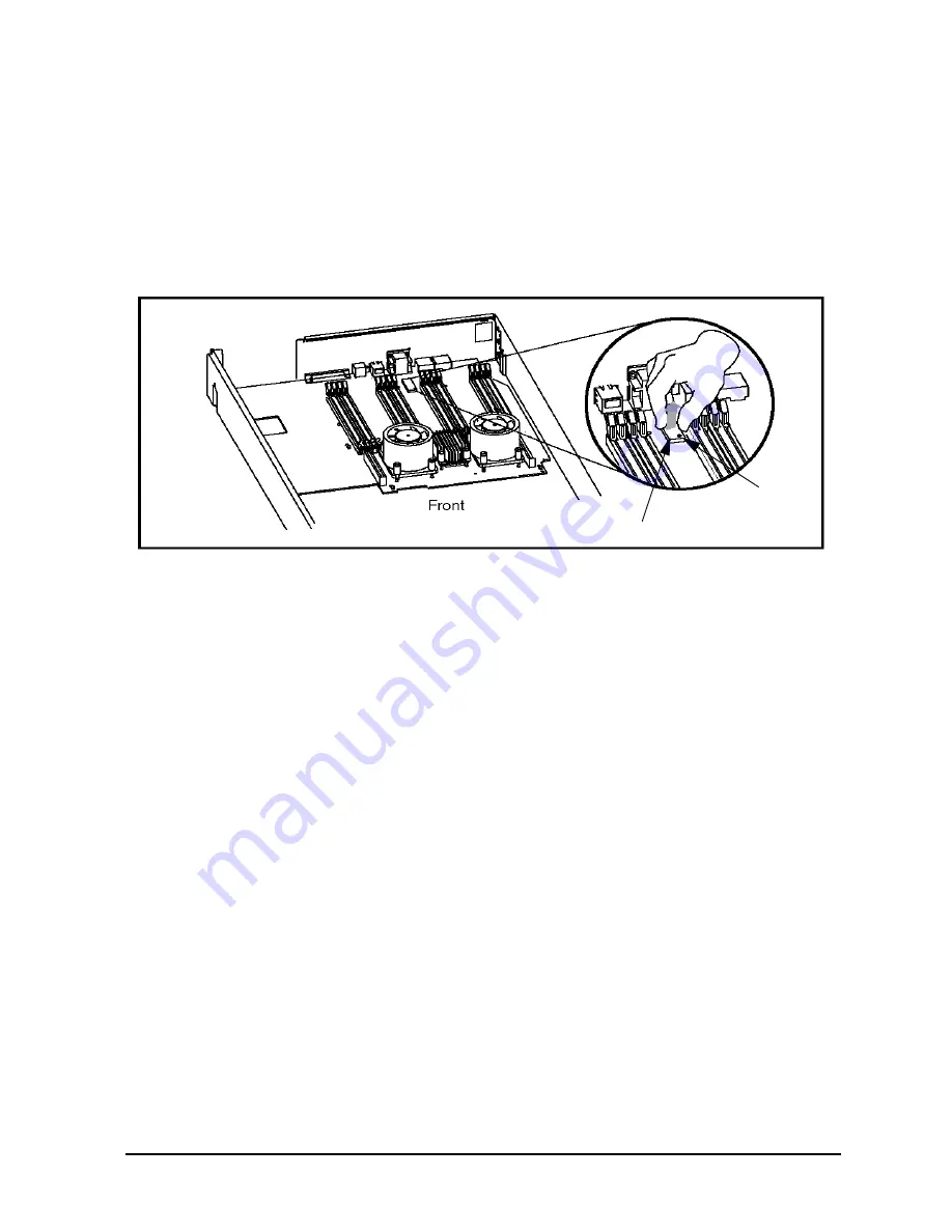
To remove the real-time clock, you first need to follow the procedure in the section “Front
Bezel and Top Cover” of this chapter. After this procedure has been completed, you can
remove the real-time clock as shown in Figure 4-14. You may need to rock the real-time
clock back and forth to loosen it in its socket.
Figure 4-14. Removing the Real-Time Clock
To replace the real-time clock, reverse the above procedure. Note that you should be
careful to not bend any of the real-time clock’s pins, and you must position the locator dot
as shown in Figure 4-14. Once the real-time clock is in place, reverse the procedure in the
section “Front Bezel and Top Cover” to replace the top cover.
Real-time Clock
Locator Dot
Содержание j6700
Страница 1: ...Service Handbook HP VISUALIZE J6700 Workstations Manufacturing Part Number n a Edition E0501 ...
Страница 8: ...8 Contents ...
Страница 30: ...30 Chapter1 Product Information Monitors ...
Страница 37: ...Chapter 3 37 Troubleshooting Flowcharts for Troubleshooting Figure 3 1 Main Flowchart for Troubleshooting ...
Страница 38: ...38 Chapter3 Troubleshooting Flowcharts for Troubleshooting Figure 3 2 Console Troubleshooting Flowchart ...
Страница 40: ...40 Chapter3 Troubleshooting Flowcharts for Troubleshooting Figure 3 4 HP UX Troubleshooting Flowchart ...
Страница 76: ...76 Chapter3 Troubleshooting Using the System Board LEDs for Troubleshooting ...
Страница 100: ...100 Chapter4 Field Replaceable Units FRUs FRU Removal and Replacement ...
Страница 134: ...134 Chapter5 Boot Console Handler Initial System Loader ISL Environment ...
Страница 135: ...135 6 Block Diagram This chapter contains the block diagram for the J6700 workstation s system board and PCI board ...
Страница 150: ...150 Appendix B SCSI Connections How To Connect An SE SCSI Device ...


