


12
Installing the Module in an Unused Slot
8.
After you connect the switch to the FDDI ring, check the port LEDs for
the newly-installed FDDI Module to ensure that the module is enabled.
If
you have not already done so, install the LED label strip for the FDDI
Module, as described in step 1 on page 7.
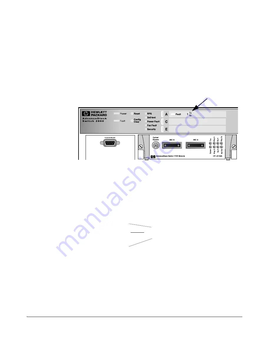
For example, if you installed the FDDI Module in slot A, the port LEDs for
the module would be found in the location shown below:
Figure 5.
Locating the Port LEDs for an FDDI Module in Slot A
The “port-enabled'' LED (
1
) will be lit if the FDDI port is enabled. The
transmit (Tx) and/or receive (Rx) LEDs will flash when traffic is detected
on the port.
Figure 6.
Port LEDs for the Switch 2000 FDDI Module
9.
Customize the port configuration, if necessary. (See “Customizing the
Port Configuration” below.)
10. Reboot the switch, since this is a new module being installed. (See
“Rebooting the Switch”, below, for more information on when the switch
must be rebooted.)
Port LEDs for Slot A
Port-enabled LED
Transmit LED
Receive LED
1
Tx
Rx


