background image


34 

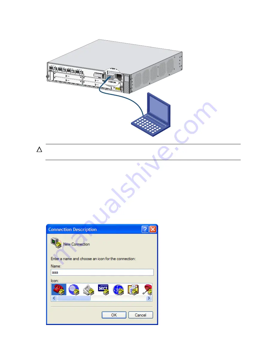
Figure 46


Connecting the console cable 


CAUTION: 

To disconnect a PC from the router, disconnect the RJ-45 connector first. 


Setting terminal parameters 

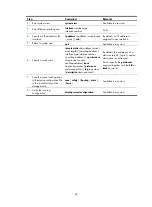
To set terminal parameters, for example, on a Windows XP HyperTerminal: 

1.


Select 

Start

 > 

All Programs

 > 

Accessories

 > 

Communications

 > 

HyperTerminal

The 

Connection Description

 dialog box appears.  

2.


Enter the name of the new connection in the 

Name

 field and click 

OK

.  

Figure 47


Connection description for the HyperTerminal 


Содержание HSR6602-G

Страница 1: ...HP HSR6600 Routers Installation Guide Part number 5998 3100 Document version 6PW105 20140210 5998 3100 ...

Страница 2: ...MATERIAL INCLUDING BUT NOT LIMITED TO THE IMPLIED WARRANTIES OF MERCHANTABILITY AND FITNESS FOR A PARTICULAR PURPOSE Hewlett Packard shall not be liable for errors contained herein or for incidental or consequential damages in connection with the furnishing performance or use of this material The only warranties for HP products and services are set forth in the express warranty statements accompan...

Страница 3: ...in a 19 inch rack 9 Grounding the router 11 Installing the ring terminal 11 Connecting the grounding cable 12 Installing a power module 13 Installing a FIP module 13 Installing a HIM MIM 14 Installing a CF card 15 Connecting the power cord 16 Connecting an AC power cord 16 Connecting a DC power cord 16 Connecting the router to the network 18 Connecting the AUX cable 18 Overview 18 Connecting the A...

Страница 4: ...n to replace a memory module 47 Replacing a memory module 47 Hardware management and maintenance 49 Displaying hardware information of the router 49 Displaying the software and hardware version information of the router 49 Displaying the operational statistics of the router 50 Displaying the detailed information about a module 50 Displaying the electrical label information of a module 51 Displayin...

Страница 5: ...y is enabled 66 Dealing with user privilege level password loss when password recovery capability is enabled 67 Dealing with password loss when password recovery capability is disabled 68 Cooling system failure 69 Interface module cable and connection failure 70 Software upgrade failures 70 No response from the serial port 70 TFTP upgrade failure 70 FTP upgrade failure 71 Application file missing ...

Страница 6: ...s 89 Minimum curvature radius of fibers 89 Labeling cables 89 Cable management guidelines 90 Cable routing example 92 Appendix D Arranging slots and numbering interfaces 94 Slot arrangement 94 Slot arrangement for FIPs 94 Numbering interfaces 95 Examples 95 Example 1 95 Example 2 95 Support and other resources 97 Contacting HP 97 Subscription service 97 Related information 97 Documents 97 Websites...

Страница 7: ...ns Safety symbols When reading this document note the following symbols WARNING means an alert that calls attention to important information that if not understood or followed can result in personal injury CAUTION means an alert that calls attention to important information that if not understood or followed can result in data loss data corruption or damage to hardware or software General safety r...

Страница 8: ...er damage Use a safety hand truck when you move a heavy device or multiple devices Before you move the router remove all the cables USB devices mounting brackets and cable management brackets If the router needs to be moved over a long distance remove all the field replaceable units FRUs such as power modules fan trays and interface modules and package them separately and install the filler panels...

Страница 9: ...ture Operating temperature 0 C to 45 C 32 F to 113 F Storage temperature 40 C to 70 C 40 F to 158 F Table 3 Humidity requirements Item Relative humidity Operating humidity 5 to 95 Storage humidity 5 to 95 Altitude Table 4 Altitude requirements Item Altitude Operating altitude 60 m 196 85 ft to 4 km 2 49 miles Storage altitude 60 m 196 85 ft to 4 5 km 2 8 miles Cleanness Dust buildup on the chassis...

Страница 10: ...for good ventilation Make sure the installation site has a good cooling system ESD prevention To prevent electrostatic discharge ESD note the following guidelines Make sure that the router and rack are well grounded An anti static floor is installed and well grounded Maintain the humidity and temperature at a proper level in the equipment room For more information see Temperature and humidity Alwa...

Страница 11: ...nd The HSR6600 does not provide any ESD preventive wrist strap Prepare it yourself Figure 2 Use an ESD preventive wrist strap 1 ESD preventive wrist strap 2 Lock 3 Alligator clip EMI All electromagnetic interference EMI sources from outside or inside of the router and application system adversely affect the router in a conduction pattern of capacitance coupling inductance coupling electromagnetic ...

Страница 12: ... supply Perform the following steps to satisfy the power supply requirements of the HSR6600 routers 1 Calculate the system power consumption The system power consumption of the HSR6600 routers depends on the number and type of interface modules and fan tray power consumption For the power consumption of the router see Appendix A Chassis views and Technical specifications 2 Select power modules acc...

Страница 13: ... with router Front mounting bracket and cable management bracket supplied with router Load bearing screw supplied with router Rubber feet supplied with router M6 screw user supplied Cage nuts user supplied ESD preventive wrist strap user supplied Cable tie user supplied Insulation sheath user supplied Ring terminal user supplied ...

Страница 14: ...talling an HSR6600 router Make sure that you have read Preparing for installation carefully and the installation site meets all the requirements Prepare a 19 inch rack Make sure that the rack is sturdy and securely grounded Make sure that there is sufficient clearance around the rack for heat dissipation and installation Make sure that there is no debris inside or around the rack Move the router t...

Страница 15: ...on The HSR6600 Routers are installed in the same way The HSR6602 G is used as an example in this section To install the router in a rack 1 Mark the positions of cage nuts on the front rack posts by using a front mounting bracket and mark the positions of cage nuts on the rear rack posts by using a rear mounting bracket See Figure 5 Figure 5 Marking the positions of the cage nuts 2 Insert one edge ...

Страница 16: ...ling cage nuts 3 Install the cable management brackets See Figure 7 Figure 7 Installing the front mounting brackets and load bearing screws 4 Install the router to the rack CAUTION This task requires at least two people ...

Страница 17: ...able as appropriate for connecting to the grounding strip and strip 5 mm 0 20 in of insulation sheath by using a wire stripper 2 Insert the bare metal part through the black insulation covering into the end of the ring terminal 3 Crimp the metal part of the cable to the ring terminal with a crimper 4 Cover the joint with the insulation covering and heat the insulation covering with a blow dryer to...

Страница 18: ... 2 Attach the grounding screw to the ring terminal of the grounding cable 3 Use a screwdriver to fasten the grounding screw into the grounding screw hole 4 Attach the ring terminal on the other end of the grounding cable to the grounding strip Figure 10 Connecting the grounding cable Insulation sheath Ring terminal 1 2 3 4 Grounding cable 5mm ...

Страница 19: ... guide rails into the slot 3 Fasten the captive screws on the power module with a Phillips screwdriver Figure 11 Installing the power module NOTE For the power module LED description see Appendix B LEDs An AC power module and a DC power module cannot be installed on the same router Installing a FIP module NOTE Before you install a FIP module make sure that the ejector levers are in the open positi...

Страница 20: ...the HIM module panel The procedures for installing HIMs and MIMs are similar This example installs a MIM to a FIP 20 To install a MIM 1 Locate the slot to install the MIM on the FIP module 2 Loosen the captive screws on a filler panel with a Phillips screwdriver and then use a flat blade screwdriver to prize the filler panel to remove it from the router Keep the filler panel safe for future use 3 ...

Страница 21: ...g clip at the right of the CF card cover to open it Figure 14 Open the CF card cover 2 Press the ejector button next to the CF card slot Insert the CF card into the slot and make sure it does not project from the slot Figure 15 Insert the CF card 3 Close the CF card cover ...

Страница 22: ... 4 Pull the bail latch down to secure the plug to the power receptacle 5 Connect the other end of the power cord to the AC power outlet Figure 17 Connecting an AC power cord to the router Connecting a DC power cord To connect a DC power cord 1 Correctly orient the plug at one end of the cable with the power receptacle on the power module and insert the plug into the power receptacle The power rece...

Страница 23: ...he plug 2 Tighten the screws on the plug with a flat blade screwdriver to secure the plug in the power receptacle Figure 19 Tighten the screws 3 Connect the two wires at the other end of the power cord to a DC power source ...

Страница 24: ...for connecting to the AUX port of the router and DB 25 and DB 9 male connectors at the other end for connecting to the serial port of the modem Figure 20 AUX cable Connecting the AUX cable 1 Plug the DB 9 or DB 25 male connector at one end of the AUX cable into the serial port of the modem 2 Plug the RJ 45 connector of the AUX cable into the AUX port of the router ...

Страница 25: ... are mainly used in 1000 Mbps Ethernet networks Category 6 cables provide a transmission frequency of 1 MHz to 250 MHz and improve the performance on crosstalk and return loss A fine better return loss performance is extremely important for new generation full duplex high speed networks Category 6 cables have sufficient power sum ACR PS ACR when working at 200 MHz They provide a bandwidth two time...

Страница 26: ...te brown stripe pin 8 brown solid Ethernet twisted pair cables can be classified into straight through and crossover cables based on their pinouts For the pinouts of the twisted pair cables see the following tables A and B represent the two ends of a cable respectively Table 7 Straight through cable pinouts Pinout No A B 1 Orange white Orange white 2 Orange Orange 3 Green white Green white 4 Blue ...

Страница 27: ...imping pliers until you hear a click 6 Use a cable tester to verify the proper connectivity of the cable Connecting an Ethernet cable 1 Plug one end of an Ethernet twisted pair cable into the copper Ethernet port RJ 45 port to be connected on the router and the other end of the cable into the Ethernet port of the peer device The 10 100 1000Base T copper ports of the router support MDI MDI X auto s...

Страница 28: ...tical fiber can connect these types of interface modules HIM 4GBP HIM 8GBP HIM CL1P HIM CL2P HIM CLS1P HIM CLS2P HIM MSP2P HIM MSP4P HIM PS1P HIM AL1P HIM AL2P HIM RS2P or HIM 1EXP Optical fibers feature low loss and long transmission distance Optical fibers can be classified into single mode fibers and multi mode fibers A single mode fiber carries only a single ray of light a multi mode fiber car...

Страница 29: ...e of several thousand meters Uses LEDs as the light source often within LANs or distances of a couple hundred meters within a campus network Table 10 Allowed maximum tensile force and crush load Period of force Tensile load N Crush load N mm Short period 150 500 Long term 80 100 Fiber connectors are indispensable passive components in an optical fiber communication system They allow the removable ...

Страница 30: ...bending along the acute side of mechanical parts the fiber must wear jackets or cushions Insert and remove a plug with care Never exert a fierce force to the fiber or plug otherwise the plug may be damaged or the fiber may be broken Never pull press or extrude the fiber fiercely For the allowed maximum tensile load and crush load see Table 10 Connecting a fiber cable WARNING Do not stare into any ...

Страница 31: ...e E1 T1 cable overview E1 cable You can use an 8E1 interface cable to connect to MIM 8E1 75 MIM 8E1 75 F modules Figure 28 8E1 splitter cable NOTE The coaxial connector and 75 ohm E1 adapter cable are optional accessories and must be purchased separately if needed ...

Страница 32: ... cable D15 D68 BNC CAUTION When connecting the interface cable pay attention to the mark on the interface to avoid wrong insertion which may damage the interface module or even the router If you do not need to extend the cable you can directly connect the BNC connectors of the E1 75 ohm cable to the remote network device as follows a Connect the D15 D68 connector of the E1 75 ohm cable to the D15 ...

Страница 33: ...igure 31 Connect an E1 75 ohm cable If the impedance of the E1 interface on the remote device is 120 ohms you must use an impedance converter to adapt the impedance Figure 32 Connecting an impedance converter Connecting a T1 cable 1 Connect the D68 connector of the 8 port T1 cable to the D68 interface on the interface module and fasten the bolts to fix the cable E1 E1 F 75ohm TX RX Device 120ohm E...

Страница 34: ...e CAUTION HP recommends that you install a special lightning protector at the input end of the E3 T3 cables to protect them against lightning strikes more efficiently when they are routed outdoors Connecting a CE3 CT3 cable 1 Connect the SMB connector of an E3 T3 cable to the Tx port on the interface module and the other end to the Rx port on the device to be connected 2 Connect the SMB connector ...

Страница 35: ... cable Connecting a serial port cable Overview You can use a serial port cable to connect to the MIM 2SAE MIM 4SAE MIM 8SAE module Select a serial port cable according to the link type Figure 36 V 24 DTE cable Figure 37 V 24 DCE cable ...

Страница 36: ...30 Figure 38 V 35 DTE cable Figure 39 V 35 DCE cable Figure 40 X 21 DTE cable Figure 41 X 21 DCE cable A A Pos 28 Pos 1 X1 W X2 B B A Pos 1 Pos 15 A W B Pos 28 X1 Pos 1 B X2 ...

Страница 37: ...ecting a serial port cable 1 Check port type of the peer device and choose the synchronous serial interface cable of correct type 2 Plug the D28 end of the synchronous serial interface cable into the D28 interface of the SAE interface module 3 If the WAN uses DDN line connect the cable to the port of the CSU DSU ...

Страница 38: ...32 4 Check the LINK LED on the SAE panel If the LED is on a link is present If the LED is off a fault has occurred on the link and signal is out of synchronization In this case check the link ...

Страница 39: ...t Logging in through the console port Preparation Before you log in to your router prepare an 8 core shielded cable with a crimped RJ 45 connector at one end and a DB 9 male connector at the other end and a PC with the operating system Windows 95 98 NT 2000 XP 7 Setting up a configuration environment To connect a configuration terminal to the router by using the console cable 1 Select a configurat...

Страница 40: ...g terminal parameters To set terminal parameters for example on a Windows XP HyperTerminal 1 Select Start All Programs Accessories Communications HyperTerminal The Connection Description dialog box appears 2 Enter the name of the new connection in the Name field and click OK Figure 47 Connection description for the HyperTerminal ...

Страница 41: ...Figure 48 Setting the serial port used by the HyperTerminal connection 4 Set Bits per second to 9600 Data bits to 8 Parity to None Stop bits to 1 and Flow control to None and click OK Figure 49 Setting the serial port parameters 5 Select File Properties in the HyperTerminal window ...
Страница 42: ...36 Figure 50 HyperTerminal window 6 On the Settings tab set the emulation to VT100 and click OK Figure 51 Setting terminal emulation in aaa Properties dialog box ...

Страница 43: ...installed Powering on the router Power on the router and you can see the following information System is starting Booting Normal Extend BootWare HP HSR6600 Router BootWare Version 1 01 Copyright c 2010 2012 Hewlett Packard Development Company L P Compiled Date Nov 14 2011 CPU Type P4080 CPU L1 Cache 32KB CPU Clock Speed 1500MHz Memory Type DDR3 SDRAM Memory Size 4096MB Memory Speed 650MHz BootWare...

Страница 44: ...or more information about how to log in to the router through Telnet see HP A6600 Routers Configuration Guides Logging in to the router through the AUX port To log in to the router through the AUX port 1 After powering on the router connect the console cable to the console port and follow these steps to configure the AUX port Step Command 1 Enter system view system view 2 Enter AUX user interface ...

Страница 45: ...idle cut disable self service url disable user group system group attribute allow guest interface NULL0 interface GigabitEthernet0 0 0 interface GigabitEthernet0 0 1 interface GigabitEthernet0 0 2 interface GigabitEthernet0 0 3 interface M GigabitEthernet0 0 0 load xml configuration user interface con 0 user interface aux 0 user interface vty 0 4 Configuring basic settings To configure basic setti...

Страница 46: ... hop address interface type interface number next hop address vpn instance d vpn instance name next hop address track track entry number preference preference value tag tag value description description text By default the preference of a static route is 60 tag is 0 and no description is configured Do not specify the permanent keyword together with the bfd or track keyword 7 Save the current confi...

Страница 47: ...e module Put the removed module on an antistatic workbench with the PCB side facing upward or place them in antistatic bags Replacing a power module The replacement procedure of an AC power module is the same as a DC power module This section takes an AC power module as an example To replace a power module 1 Use a Philips screwdriver to loosen the captive screws of the power module to be removed u...

Страница 48: ...lot along the slide rails Figure 53 Pulling the FIP module out of the slot 4 If you do not install a new FIP module in the slot install a blank panel To install a new FIP module see Installing a FIP module NOTE To replace a FIP module when the router is running perform the remove slot slot number command and then unplug the module Replacing a HIM MIM NOTE To replace a HIM MIM module when the route...

Страница 49: ... To avoid hardware damage do not remove the CF card when the router is booting or the CF LED is flashing Before you replace a CF card open the CF card cover first For more information see Installing a CF card 1 Press the ejector button next to the CF card The ejector button moves outward so that it projects from the panel Figure 55 Press the ejector button 2 Press the ejector button again This eje...

Страница 50: ... a transceiver module 1 Remove the optical fibers from the transceiver module 2 Pivot the clasp down to the horizontal position 3 Holding the handle of the transceiver module gently pull the transceiver module out See Figure 57 4 Insert the plastic plug to the removed transceiver module and put the transceiver module into its original shipping materials 5 If you do not install a new transceiver mo...

Страница 51: ...rious injury or cut Make sure that all fans have stopped rotating before you take out the entire fan tray CAUTION Do not operate the system without a fan tray for more than 2 minutes To replace a fan tray 1 Use a Phillips screwdriver to loosen the captive screw on the fan tray 2 Grasp the handle of the fan tray with one hand and pull the fan tray part way out the slot Support the fan tray bottom w...

Страница 52: ...omatic fan speed adjustment and hot swapping fan trays are supported Put the removed fan tray in an anti static bag Replacing a memory module CAUTION Keep the tamper proof seal on a mounting screw on the chassis cover intact and if you want to open the chassis contact the local agent of HP for permission Otherwise HP shall not be liable for any consequence caused thereby Use the memory modules pro...

Страница 53: ...ns More memory is needed to upgrade the application program The router needs to maintain a large routing table or support other highly memory consuming operations An existing memory module is damaged Replacing a memory module Opening the chassis cover CAUTION Screws are available at both sides inside the chassis cover To avoid damaging the router do not use excessive force when you pull the chassi...

Страница 54: ... 62 Opening the chassis cover Replacing a memory module Figure 63 Replacing a memory module CAUTION Align the polarization notch of the memory module with the key in the connector when you insert a memory module ...

Страница 55: ...012 Hewlett Packard Development Company L P HP HSR6602 uptime is 0 week 0 day 0 hour 1 minute Slot 0 HSR6602 XG uptime is 0 week 0 day 0 hour 1 minute CPU type FREESCALE P4080 1500MHz 4096M bytes DDR3 SDRAM Memory 8M bytes Flash Memory 128K bytes NVRAM PCB Version Ver A Basic Logic Version 1 0 Extend Logic Version 1 0 Basic BootWare Version 1 00 Extend BootWare Version 1 00 FIXED PORT CON Hardware...

Страница 56: ...cceeded Execute the more aa diag command in user view and then press the Page Up and Page Down keys to view the contents of the file aa diag To display the operational statistics of each functional module of the router type n when the system prompts you to save or display the diagnostic information The output is too much and omitted here Sysname display diagnostic information Save or display diagn...

Страница 57: ...el information of the module in each slot Electrical label information is also called permanent configuration data or archive information which includes the module name serial number MAC address and vendor name Sysname display device manuinfo Slot 0 DEVICE_NAME HSR6602 XG JG354A DEVICE_SERIAL_NUMBER CN12FRX123 MAC_ADDRESS 000F E123 4567 MANUFACTURING_DATE 2012 02 02 VENDOR_NAME HP Slot 1 DEVICE_NA...

Страница 58: ... Sysname display cpu usage Slot 0 CPU usage 1 in last 5 seconds 1 in last 1 minute 1 in last 5 minutes Table 13 Output description Field Description Slot 0 CPU usage CPU usage of the module in slot 0 1 in last 5 seconds Average CPU usage in the last five seconds after the router boots the router calculates and records the average usage at the interval of five seconds 1 in last 1 minute Average CPU...

Страница 59: ...n Slot No Slot number of the CF card Dev No Device number of the CF card 0 for a built in CF card 1 for an external CF card Status Operational status of the CF card Absent No CF card is present in the slot Fault The CF card fails Normal The CF card is operating properly Size M Storage capacity of the CF card Displaying the operational status of the built in fan Use the display fan command to displ...

Страница 60: ...thresholds of a module Step Command Remarks 1 Enter system view system view N A 2 Optional Display the temperature information of your router display environment Available in any view Configuring a combo interface Combo interface overview A combo interface is a logical interface comprising an SFP port of a transceiver module and an RJ 45 Ethernet port The two ports share one forwarding interface s...

Страница 61: ...rruns 0 collisions 0 deferred 0 lost carriers If the output includes Media type is twisted pair loopback not set promiscuous mode not set it means that the interface is an RJ 45 Ethernet port For example the following output shows that GigabitEthernet 0 0 1 is an RJ 45 Ethernet port Sysname display interface GigabitEthernet 0 0 1 GigabitEthernet0 0 1 current state DOWN Line protocol current state ...

Страница 62: ...tion to transceiver modules Table 18 Commonly used transceiver modules Transceiver module type Application scenarios Whether can be an optical transceiver Whether can be an electrical transceiver SFP Small Form factor Pluggable Generally used for 100 1000 Mbps Ethernet ports or POS 155M 622M 2 5G ports Yes Yes XFP 10 Gigabit Small Form Factor Pluggable Generally used for 10 Gbps Ethernet ports Yes...

Страница 63: ...face interface type interface number Available for all transceiver modules NOTE For more information about the transceiver module displaying commands see HP A6600 Routers Command References Solving system faults Solving system faults When the system detects faults such as system instruction faults invalid addresses data overflow null pointers and division by zero operations during the operation of...

Страница 64: ...et as the file for the next startup save file url Use either command Available in any view Save the current configuration to the root directory of the storage medium of the active or standby device and specify the file as the startup configuration file that will be used at the next system startup save safely NOTE The configuration file must be with extension cfg During the execution of the save co...

Страница 65: ...elay hh mm mm CAUTION If the main system software image file does not exist do not use the reboot command to reboot the router Specify the main system software image file first and then reboot the router The precision of the rebooting timer is 1 minute One minute before the rebooting time the router prompts REBOOT IN ONE MINUTE and reboots in one minute If you are performing file operations when t...

Страница 66: ...the problem persists contact your local sales agent RUN LED is off When the RUN LED of the router is off it indicates that the router is faulty For more information about the RUN LED see Appendix B LEDs To troubleshoot the problem contact your local sales agent RUN LED fast flashes Five minutes after the router is powered on if the RUN LED still fast flashes at 8 Hz it indicates that the system so...

Страница 67: ...ng power properly Steady red No power is input or the power module is faulty when PWR1 is operating properly FAN red green Off No power is input or the fan tray is not is position Steady green The fan tray is operating properly Steady red The fan tray is faulty ALM red Steady on No alarm exists Off The router is faulty You need to view the system logs immediately RUN green Off No power is input or...

Страница 68: ...cription LED Status Description Input Off No power is input or the power supply is faulty Steady green The power supply is working properly Output Off No power is input Steady green The power supply is working properly Fan failures Fan tray is absent After the router is booted the following information may appear on the configuration terminal Dec 9 09 57 12 560 2011 HP DEVM 1 FAN STATE CHANGES TO ...

Страница 69: ...264 2011 66mcp DRVICOUT 1 DrvIcOutStr Card in Slot 4 Sublot 2 can not be recognized The output indicates that the HIM MIM is faulty or the router cannot recognize the HIM MIM To troubleshoot the HIM MIM failure 1 Check whether the HIM MIM is firmly seated 2 Check whether the HIM is correctly plugged into an FIP 20 module An FIP 10 module does not support HIMs 3 Check whether the interface module c...

Страница 70: ...terminal to display garbled characters No response from the serial port If the serial port gives no response check that the serial port settings are correct NOTE For more information about the serial port settings see Setting terminal parameters Dealing with password loss CAUTION Dealing with console login password loss and user privilege level password loss from BootWare menus is disruptive How t...

Страница 71: ...ooting Normal Extend BootWare The Extend BootWare is self decompressing Done HP Router BootWare Version 1 04 Copyright c 2010 2012 Hewlett Packard Development Company L P Compiled Date Dec 26 2012 CPU Type P2020 CPU L1 Cache 32KB CPU Clock Speed 1000MHz Memory Type DDR3 SDRAM Memory Size 4096MB Memory Speed 667MHz Flash Size 8MB cfa0 Size 999MB NVRAM Size 128KB BASIC CPLD Version 1 0 EXTEND CPLD V...

Страница 72: ...m 2 Enter Serial SubMenu 3 Enter Ethernet SubMenu 4 File Control 5 Restore to Factory Default Configuration 6 Skip Current System Configuration 7 BootWare Operation Menu 8 Clear Super Password 9 Storage Device Operation 0 Reboot Ctrl Z Access EXTEND ASSISTANT MENU Ctrl F Format File System Enter your choice 0 9 Dealing with console login password loss when password recovery capability is enabled 1...

Страница 73: ...n mode is password and the authentication password is 123456 For security the password is always saved in ciphertext to the configuration file regardless of whether you specify the simple keyword or cipher keyword for the set authentication password command HP system view HP user interface console 0 HP ui console0 authentication mode password HP ui console0 set authentication password cipher 12345...

Страница 74: ...dless of whether you specify the simple keyword or cipher keyword for the super password command HP system view HP super password cipher 123456 4 To make the setting take effect after a reboot save the running configuration to the next startup configuration file HP save Dealing with password loss when password recovery capability is disabled 1 Reboot the router to access the EXTEND BOOTWARE menu a...

Страница 75: ...VM 1 BOARD TEMPERATURE UPPER Trap 1 3 6 1 4 1 25506 8 35 12 1 16 chassisIndex is 0 slotIndex 0 0 Dec 7 11 49 20 444 2011 HP DEVM 4 BOARD_TEMP_TOOHIGH Board temperature is too high on Chassis 0 Slot 0 type is HSR6602 XG After the router runs for a period of time the environmental temperature of the router will drop below the high temperature threshold and the following information appears on the co...

Страница 76: ...nected 3 Use the display command to check whether the interface of the interface module has been correctly configured and is working properly Software upgrade failures No response from the serial port The serial port gives no response To solve the problem check whether the serial port settings are correct whether the Bits per second field is set to 9600 kbps NOTE For more information about the ser...

Страница 77: ...r the application program 2 The file to be downloaded is not found 227 Entering Passive Mode 192 168 1 10 10 203 550 Error File xxx does not exist FTP Error Writing Local File Screen To solve this problem type the correct file name 3 The configuration of the network port is incorrect FTP Unrecognized host or wrong IP address To solve this problem configure the network port correctly and make sure ...

Страница 78: ...lication files vary by user settings A possible reason for the errors is that the main backup and secure application files have been deleted or damaged To solve this problem download the application package again or set the file properties in the BootWare file list ...

Страница 79: ...igure 65 HSR6602 G HSR6602 G TAA front view 1 1000 Mbps Ethernet port 2 CF card slot CF CARD 3 CF card LED 4 Status LED 5 USB port 6 Reset button RESET 7 Auxiliary port AUX 8 Console port CONSOLE 9 Management Ethernet port MANAGEMENT 10 FIP slot slot 1 4 1 2 3 5 7 6 8 9 10 ...

Страница 80: ... port AUX 9 Console port CONSOLE 10 Management Ethernet port MANAGEMENT 11 FIP slot slot 1 Figure 67 HSR6600 rear view 1 Power module slots PWR1 PWR2 2 Grounding screw 3 Grounding sign 4 Fan tray Dimensions and weights Table 23 Dimensions and weight Item Dimensions H W D Weight Chassis 88 440 480 mm 3 46 17 32 18 90 in 12 1 kg 26 68 lb FIP module 45 399 412 mm 1 77 15 71 16 22 in 3 kg 6 61 lb ...

Страница 81: ...n HSR6602 G HSR6602 G TAA 160 W HSR6602 XG HSR6602 XG TAA 160 W Card power consumption FIP 10 33 W FIP 20 65 W Fan tray power consumption 30 W Interface module power consumption See HP 6600 HSR6600 HSR6800 Router Series Interface Module Guide Power module Each HP HSR6600 router provides two power module slots PWR1 and PWR2 on its rear panel and is shipped with a filler panel on PWR2 You can instal...

Страница 82: ...s Item Specification Model PSR300 12A Rated voltage range 100 VAC to 240 VAC 50 Hz or 60 Hz Maximum input current 4 A Maximum power 300 W DC power module The supported DC power module is PSR300 12D1 which provides a maximum output power of 300 W Figure 69 DC power module appearance 1 DC input terminal block 2 Power input status LED 3 Power output status LED 4 Handle 5 Power switch ...

Страница 83: ...R6600 router provides a fan tray slot on its rear panel You can install a fan tray for heat dissipation NOTE The fan tray is supplied with the router Figure 70 Fan tray 1 Handle Table 28 Fan tray specifications Item Specification Model RT FANF Automatic speed adjustment Supported Fool proof design Supported Hot swapping Supported Noise level 55dBA to 65dBA Heat dissipation 102 BTU 1 ...

Страница 84: ...t specifications Item Specification Connector RJ 45 Standard compliant Asynchronous EIA TIA 232 Baud rate 9600 bps default to 115200 bps Transmission distance 15 m 49 21 ft Services Provides connection to the serial port of a local PC to run the terminal emulation program AUX port Table 31 AUX port specifications Item Specification Connector RJ 45 Standard compliant Asynchronous EIA TIA 232 Baud r...

Страница 85: ...uplex mode 10 Mbps half full duplex 100 Mbps half full duplex 1000 Mbps full duplex Combo interface Copper Ethernet port Table 33 Copper Ethernet port specifications Item Specification Connector RJ 45 Interface type Automatic MDI MDI X Frame format Ethernet_II Ethernet_SNAP Interface speed and duplex mode 10 Mbps half full duplex 100 Mbps half full duplex 1000 Mbps full duplex NOTE The media depen...

Страница 86: ...e 9 125 μm single mode Max transmission distance 0 55 km 0 34 miles 10 km 6 21 miles 40 km 24 86 miles 40 km 24 86 miles 70 km 43 50 miles Operating mode 100 1000 Mbps full duplex 10 Gbps Ethernet port The HSR6602 XG HSR6602 XG TAA provides two 10 Gbps Ethernet ports 10 Gbps SFP ports do not support 1000 Mbps transceiver modules Table 35 10 Gbps Ethernet port specifications Item Specification Prot...

Страница 87: ...nel NOTE No FIP modules are supplied with the router Purchase them yourself FIP 10 The FIP 10 supports only MIMs and you can plug at most four MIMs into a FIP Figure 71 FIP 10 front panel 1 Slot 4 2 Slot 3 3 OPEN BOOK mark 4 Status LED RUN 5 Slot 1 6 Slot 2 The OPEN BOOK mark indicates that the operator must read the following sections before working with the FIP Table 37 References for FIP operat...

Страница 88: ... the operator must read the following sections before working with the FIP Table 39 References for FIP operations Operation Reference Install and remove the FIP See Installing a FIP module and Replacing a FIP module Install and remove interface modules See 错误 未找到引用源 Installing a HIM MIM 错误 未找到引用 源 and Replacing a HIM MIM Connect network cables See Connecting an Ethernet cable Connect optical fiber...

Страница 89: ...aggregation The HIMs and MIMs can offer a variety of interfaces including serial Ethernet POS and E1 NOTE No interface modules are supplied with the router Purchase them yourself An interface module must be installed on a FIP For information about interface module specifications see HP 6600 HSR6600 HSR6800 Router Series Interface Module Guide ...

Страница 90: ...e the CF card Steady yellow It is a non HP CF card red green PWR1 Off The power module is not in position Steady green The power module is supplying power properly Steady red No power is input or the power module is faulty when PWR2 is operating properly red green PWR2 Off The power module is not in position Steady green The power module is supplying power properly Steady red No power is input or ...

Страница 91: ...nt ACT Off No data is being received or transmitted Flashing yellow Data is being received or transmitted yellow green SFP0 through SFP3 Off No link is present Steady green A 1000 Mbps link is present Flashing green Data is being received or transmitted at 1000 Mbps Steady yellow A 100 Mbps link is present Flashing yellow Data is being received or transmitted at 100 Mbps yellow green GE0 through G...

Страница 92: ... FAN Off No power is input or the fan tray is not in position Steady green The fan tray is working properly Steady red The fan tray is faulty red ALM Off The system is operating properly and there is no alarm Steady red A fault has occurred In this state check the system log immediately green RUN Off The system is powered off or the router is faulty Flashing at 1 Hz The router operates properly as...

Страница 93: ... 1000 Mbps link is present Flashing green Data is being received or transmitted at 1000 Mbps Steady yellow A 10 100 Mbps link is present Flashing yellow Data is being received or transmitted at 10 100 Mbps FIP LEDs Figure 75 FIP 10 LED Figure 76 FIP 20 LED Table 43 FIP LED description LED Status Description green Off No power input is available or the FIP has failed Flashing at 1 Hz The FIP is wor...

Страница 94: ... problem Steady green The power input is normal green Off No power is output or the power module has an output problem Steady green The power output is normal Figure 78 DC power module LED Table 45 DC power module LED description LED Status Description green Off No power is input or the power module has an input problem Steady green The power input is normal green Off No power is output or the pow...

Страница 95: ...hould be at least seven times of the cable s outer diameter If the coaxial cable is frequently bent plugged and unplugged the curvature radius should be at least 10 times the cable s outer diameter The curvature radius of a high speed cable for example SFP cable should be at least five times of the cable s outer diameter If the coaxial cable is frequently bent plugged and unplugged the curvature r...

Страница 96: ...a power cable bundle and a signal cable bundle is at least 30 mm 1 18 in The cable management brackets and cable routing slots inside or outside the rack are smooth and have no sharp edges or tips When you route cables through sharp sheet metal penetration points or along sharp edges of mechanical parts use bushings or take any other action to protect the cables from being cut or abraded The sheet...

Страница 97: ... operations Do not tie the power cables to the slide rails When you connect a cable to an articulated part for example when you connect a grounding cable to a cabinet door leave enough slack in cables and make sure they are not stressed from any movement of the part Cables must be protected at points where they might rub or come in contact with sharp edges or heated areas Use high temperature cabl...

Страница 98: ...the same direction Table 46 lists the cable bundling specifications Table 46 Cable bundling specifications Cable bundle diameter mm Space between bundles mm 10 80 to 150 10 to 30 150 to 200 30 200 to 300 Do not tie cables or bundles in a knot The metal parts of the crimped cold pressed terminal blocks such as circuit breaker cannot protrude beyond the blocks Cable routing example Cables on an HSR6...

Страница 99: ...93 Figure 83 Routing cables A 0 1 0 3 0 1 A 0 1 0 3 0 2 A 0 1 0 3 0 3 A 0 1 0 3 0 4 ...

Страница 100: ...ial synchronous and E1 ports This chapter describes how these interfaces are numbered Figure 84 Slot arrangement on the SR6602 X1 Figure 85 Slot arrangement on the SR6602 X2 NOTE The numbers in Figure 84 and Figure 85 represent corresponding slot numbers Slot arrangement for FIPs Table 47 Slot arrangement for FIPs FIPs Slot arrangement FIP 10 Slot 1 FIP 20 ...

Страница 101: ...e the sequence number Z starts from 0 on the interface module Examples Example 1 A FIP 10 is installed in slot 1 and a MIM 2GBE module is installed on the FIP 10 1 If the MIM 2GBE is installed in slot 1 of the FIP 10 the GigabitEthernet interfaces are GigabitEthernet 1 1 0 GigabitEthernet 1 1 1 2 If the MIM 2GBE is installed in slot 2 of the FIP 10 FIP 100 FIP 110 the GigabitEthernet interfaces ar...

Страница 102: ...96 GigabitEthernet 1 2 2 GigabitEthernet 1 2 3 ...

Страница 103: ...ng you will receive email notification of product enhancements new driver versions firmware updates and other product resources Related information Documents To find related documents browse to the Manuals page of the HP Business Support Center website http www hp com support manuals For related documentation navigate to the Networking section and select a networking category For a complete list o...

Страница 104: ...parated by vertical bars from which you select one choice multiple choices or none 1 n The argument or keyword and argument combination before the ampersand sign can be entered 1 to n times A line that starts with a pound sign is comments GUI conventions Convention Description Boldface Window names button names field names and menu items are in bold text For example the New User window appears cli...

Страница 105: ... 2 features Represents an access controller a unified wired WLAN module or the switching engine on a unified wired WLAN switch Represents an access point Represents a security product such as a firewall a UTM or a load balancing or security card that is installed in a device Represents a security card such as a firewall card a load balancing card or a NetStream card Port numbering in examples The ...

Страница 106: ...nfiguration 39 Displaying transceiver module information and alarming information 56 E Examining the installation site 2 Examples 95 F Fan failures 62 Fan tray 77 FIP LEDs 87 FIP module failure 61 Flexible interface platform modules 81 G General cabling requirements 89 Grounding the router 1 1 H HIM MIM failures 63 HIM MIM LEDs 88 I Installation flow 8 Installing a CF card 15 Installing a FIP modu...

Страница 107: ... Replacing a power module 41 Replacing a transceiver module 44 Router failures 60 S Safety recommendations 41 Safety recommendations 1 Saving the current configuration of the router 58 Slot arrangement 94 Slot arrangement for FIPs 94 Software upgrade failures 70 Solving system faults 57 Storage media 75 U Unpacking the router 9 ...

Отзывы: