background image

1

Product features

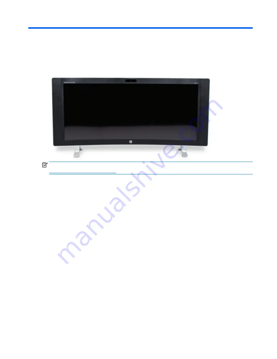
Standard configuration

NOTE:

For the latest specifications or additional specifications on this product, go to 

http://www.hp.com/go/ quickspecs/

 and search for your specific model to find the model-specific QuickSpecs.

Standard configuration

1

Содержание ENVY PRO

Страница 1: ...HP ENVY PRO Curved All in One Desktop PC Maintenance Service Guide IMPORTANT This document is intended for HP authorized service providers only ...

Страница 2: ...54095 001 Product notice This user guide describes features that are common to most models Some features may not be available on your computer Not all features are available in all editions of Windows This computer may require upgraded and or separately purchased hardware drivers and or software to take full advantage of Windows functionality Go to http www microsoft com for details Software terms...

Страница 3: ...low another hard surface such as an adjoining optional printer or a soft surface such as pillows or rugs or clothing to block airflow Also do not allow the AC adapter to contact the skin or a soft surface such as pillows or rugs or clothing during operation The computer and the AC adapter comply with the user accessible surface temperature limits defined by the International Standard for Safety of...

Страница 4: ...iv Safety warning notice ...

Страница 5: ...tion 10 Generating static 10 Preventing electrostatic damage to equipment 11 Personal grounding methods and equipment 11 Grounding the work area 11 Recommended materials and equipment 12 Operating guidelines 12 Routine care 13 General cleaning safety precautions 13 Cleaning the Computer Case 13 Cleaning the keyboard 13 Cleaning the display 14 Cleaning the mouse 14 Service considerations 14 Tools a...

Страница 6: ... connector board 39 Feet 41 System board 43 Updating SMBIOS Information 44 System ID Setup Page 45 System board callouts 45 Memory 47 Heat sink 49 Processor 50 Solid state drive M 2 51 5 Computer Setup F10 Utility 52 Computer Setup F10 Utilities 52 Using Computer Setup F10 Utilities 53 Computer Setup File 54 Computer Setup Storage 55 Computer Setup Security 56 Computer Setup Power 58 Computer Setu...

Страница 7: ...ing up restoring and recovering in Windows 10 84 Creating recovery media and backups 84 Creating HP Recovery media select products only 84 Using Windows tools 85 Restore and recovery 85 Recovering using HP Recovery Manager 86 What you need to know before you get started 86 Using the HP Recovery partition select products only 87 Using HP Recovery media to recover 87 Changing the computer boot order...

Страница 8: ...A Power cord set requirements 99 General requirements 99 Japanese power cord requirements 99 Country specific requirements 100 Appendix B Statement of Volatility 101 Appendix C Specifications 102 Index 103 viii ...

Страница 9: ... configuration NOTE For the latest specifications or additional specifications on this product go to http www hp com go quickspecs and search for your specific model to find the model specific QuickSpecs Standard configuration 1 ...

Страница 10: ...Front components Component Component 1 Internal microphones 2 5 IR projector 2 IR camera 6 Speakers 3 Webcam light 7 Power light 4 Webcam 2 Chapter 1 Product features ...

Страница 11: ...mponent 8 Audio in microphone audio out headphone combo jack 12 Volume down button 9 Memory card reader 13 Input switch up button 10 USB 3 0 charging powered port 14 Menu OK button 11 USB 3 0 port 15 Power button Bottom components 3 ...

Страница 12: ...Rear components Component Component 16 Power connector 20 USB 2 0 ports 2 17 HDMI out port 21 HDMI in port 18 USB 3 0 ports 2 22 Security cable slot 19 RJ 45 network jack 4 Chapter 1 Product features ...

Страница 13: ...Digital Product Key is automatically recognized and activated by Microsoft Operating Systems on a reinstall of the Windows 10 operating system with HP approved recovery methods Service label Provides important information to identify your computer When contacting support you will probably be asked for the serial number and possibly for the product number or the model number Locate these numbers be...

Страница 14: ...nges product parts For complete and current information on supported parts for your computer go to http partsurfer hp com select your country or region and then follow the on screen instructions System parts Item Description 1 Display ZBD NZBD 2 Front bezel 6 Chapter 2 Illustrated parts catalog ...

Страница 15: ...ed 3 Rear cover 4 I O cover 5 System board Power supply 180 W external not illustrated not illustrated Misc parts Item Description 1 Speaker woofer 2 Speaker tweeter 3 Fan 4 Heat sink 5 Stand feet Right Left 6 OSD button board 7 Audio board 8 Webcam module Misc parts 7 ...

Страница 16: ...nal optical drive DVD RW drive Hard drive 2 TB 5400 rpm 2 5 inch 1 TB 7200 rpm 2 5 inch Solid state drive not illustrated 256 GB solid state drive 2280SS PCIe 128 GB solid state drive 2280SS PCIe Processors and memory modules Description Memory module SODIMM PC4 17000 8 GB Intel Processors include replacement thermal material Intel Core i7 6700T 2 8 GHz Intel Core i5 6400T 2 2 GHz 8 Chapter 2 Illu...

Страница 17: ...Cables Description Backlight cable LCM 40 pin EDP SGN LCM 10 pin EDP PWR Transfer cable F B side Transfer cable M B side Hard drive cable Audio cable OSD cable Cables 9 ...

Страница 18: ...ally for a while but it has been degraded in the internal layers reducing its life expectancy Networks built into many integrated circuits provide some protection but in many cases the discharge contains enough power to alter device parameters or melt silicon junctions Generating static The following table shows that Different activities generate different amounts of static electricity Static elec...

Страница 19: ...e connected and fit snugly into the banana plug connector on the grounding mat or workstation Heel straps Toe straps Boot straps can be used at standing workstations and are compatible with most types of shoes or boots On conductive floors or dissipative floor mats use them on both feet with a maximum of one megohm 10 resistance between the operator and ground Static Shielding Protection Levels Me...

Страница 20: ...r on a sturdy level surface Leave a 10 2 cm 4 inch clearance on all vented sides of the computer and above the monitor to permit the required airflow Never restrict the airflow into the computer by blocking any vents or air intakes Do not place the keyboard with the keyboard feet down directly against the front of the desktop unit as this also restricts airflow Occasionally clean the air vents on ...

Страница 21: ... a mild dishwashing liquid diluted with water Rinse well by wiping it with a cloth or swab dampened with clear water For stubborn stains use isopropyl rubbing alcohol No rinsing is needed as the alcohol will evaporate quickly and not leave a residue After cleaning always wipe the unit with a clean lint free cloth Occasionally clean the air vents on the computer Lint and other foreign matter can bl...

Страница 22: ... housing Pull out any debris from the ball socket and wipe the ball with a clean dry cloth before reassembly To clean the mouse body follow the procedures in Cleaning the Computer Case on page 13 Service considerations Listed below are some of the considerations that you should keep in mind during the disassembly and assembly of the computer Tools and software Requirements To service the computer ...

Страница 23: ...turn off the computer Do not remove a hard drive while the computer is on or in standby mode Before handling a drive ensure that you are discharged of static electricity While handling a drive avoid touching the connector For more information about preventing electrostatic damage refer to Electrostatic discharge information on page 10 Do not use excessive force when inserting a drive Avoid exposin...

Страница 24: ...op of expansion cards or memory modules Printed circuit cards like these are not designed to take excessive pressure on them Keep cables clear of sliding or moveable parts to prevent them from being cut or crimped when the parts are moved When folding a flat ribbon cable never fold to a sharp crease Sharp creases may damage the wires Some flat ribbon cables come prefolded Never change the folds on...

Страница 25: ...the back of the computer 4 If a cable lock is installed on the rear of the unit remove the lock 5 Disconnect all other attached cables from the back of the computer 6 Place the computer face down on a soft flat surface HP recommends that you set down a blanket towel or other soft cloth to protect the screen surface from scratches or other damage 7 Since the computer screen is curved be sure to sta...

Страница 26: ...rews to loosen the cover Then pry the cover off the computer The following image shows screw cover locations To remove the rear bottom cover 1 Prepare the computer for disassembly see Preparing to disassemble the computer on page 17 2 Use a tool to pry the screw covers from atop the screws NOTE Only the right screw cover is shown in the following image 18 Chapter 4 Removal and Replacement Procedur...

Страница 27: ...ver disengages from the chassis 4 Pry upward along the bottom of the cover until you remove it from the computer NOTE Only the right side of the cover is shown in the following image To install the cover align it and press it down to snap it in place Rear bottom cover 19 ...

Страница 28: ...the battery it is important to back up the computer CMOS settings When the battery is removed or replaced the CMOS settings will be cleared Static electricity can damage the electronic components of the computer or optional equipment Before beginning these procedures ensure that you are discharged of static electricity by briefly touching a grounded metal object NOTE The lifetime of the lithium ba...

Страница 29: ...ery socket and the lift the battery out of the socket 1 To insert a new battery slide one edge of the replacement battery under the holder s lip with the positive side up Push the other edge down until the clamp snaps over the other edge of the battery 2 RTC battery 21 ...

Страница 30: ...o remove the USB wireless receiver 1 Prepare the computer for disassembly see Preparing to disassemble the computer on page 17 2 Remove the rear bottom cover see Rear bottom cover on page 18 3 Pull the receiver toward the right away from the slot to remove it To install the USB receiver reverse the removal procedure 22 Chapter 4 Removal and Replacement Procedures ...

Страница 31: ...sult in its breaking After you disengage the bezel from the computer only lift the bezel enough to access the webcam cables underneath If you lift the bezel too far off the chassis before disconnecting the cables you could damage the connectors To remove the bezel 1 Prepare the computer for disassembly see Preparing to disassemble the computer on page 17 2 Pry the bezel off the chassis Work around...

Страница 32: ... the bezel enough to access the cables connected to the board underneath and then disconnect both cables from the board To install the bezel reverse the removal procedures 24 Chapter 4 Removal and Replacement Procedures ...

Страница 33: ...r for disassembly see Preparing to disassemble the computer on page 17 2 Remove the bezel see Bezel on page 23 3 Remove the two Phillips screws 1 that secure the webcam module to the top of the bezel and then lift the module and place it next to the bezel 2 4 Disconnect the cable from the right 1 and left 2 microphone modules and from the webcam module 3 Remove the modules from the bezel To replac...

Страница 34: ...t below the display panel and then lift the bracket out of the computer 2 4 Remove the 12 Phillips screws 3 that secure the display panel to the computer 5 Rotate the bottom of the display panel upward to access the cables underneath Use an appropriate wedge such as a piece of foam on each side under the display to hold the display up to allow you to disconnect the cables underneath 26 Chapter 4 R...

Страница 35: ...6 Disconnect the three display cables from the system board 7 Lift the display panel off the computer To replace the display panel reverse the removal procedures Display panel 27 ...

Страница 36: ... procedure to replace the WLAN module must be performed by an HP technician To remove the WLAN module 1 Prepare the computer for disassembly see Preparing to disassemble the computer on page 17 2 Remove the bezel see Bezel on page 23 3 Remove the display panel see Display panel on page 26 4 Disconnect the antenna cables from the module 1 28 Chapter 4 Removal and Replacement Procedures ...

Страница 37: ...ay to remove it from the socket To install the WLAN module reverse the removal procedures When connecting the antennas cables connect the white cable to the Main connector on the module and the black cable to the Aux connector on the module NOTE WLAN modules are designed with a notch to prevent incorrect insertion WLAN module 29 ...

Страница 38: ...e hard drive 1 Prepare the computer for disassembly see Preparing to disassemble the computer on page 17 2 Remove the bezel see Bezel on page 23 3 Remove the display panel see Display panel on page 26 4 Slide the label holder out so you can gain access to the hard drive 5 Disconnect the hard drive cable from the system board 1 6 Remove the three screws 2 that secure the hard drive assembly to the ...

Страница 39: ... drive 1 remove the four screws that secure the hard drive to the bracket 2 and slide the drive out of the bracket 3 To install a hard drive reverse the removal procedures Make sure all four rubber screw grommets are installed correctly for each screw in the bracket as shown in the following image Hard drive 31 ...

Страница 40: ...ble the computer on page 17 2 Remove the bezel see Bezel on page 23 3 Remove the display panel see Display panel on page 26 4 Disconnect the cable from the board 1 5 Remove the tape from the board 2 6 While pulling the tab away from the board 3 lift the board out of the computer 4 To install the OSD board reverse the removal procedures 32 Chapter 4 Removal and Replacement Procedures ...

Страница 41: ...isassemble the computer on page 17 2 Remove the bezel see Bezel on page 23 3 Remove the display panel see Display panel on page 26 4 Disconnect the cable from the audio board 1 5 Remove the two Phillips screws 2 that secure the trim to the computer 6 Remove the audio board from the computer 3 To install the audio board reverse the removal procedures Audio board 33 ...

Страница 42: ...ing to disassemble the computer on page 17 2 Remove the bezel see Bezel on page 23 3 Remove the display panel see Display panel on page 26 4 Disconnect the fan cable from the system board 1 5 Remove the three Phillips screws that secure the fan to the computer 2 6 Remove the fan from the computer 3 To install the fan assembly reverse the removal procedures 34 Chapter 4 Removal and Replacement Proc...

Страница 43: ... 14 screws in both speakers To remove the speakers 1 Prepare the computer for disassembly see Preparing to disassemble the computer on page 17 2 Remove the bezel see Bezel on page 23 3 Remove the display panel see Display panel on page 26 4 Remove the bracket from the top of the computer by removing the two Phillips screws 1 and then lifting the bracket out of the computer 2 Speakers 35 ...

Страница 44: ...5 Disconnect the speaker cables from the system board 6 Remove seven Phillips screws that secure each speaker assembly to the computer 36 Chapter 4 Removal and Replacement Procedures ...

Страница 45: ...from the routing path at the top of the computer NOTE Be sure to carefully note the routing of the speaker cables along the top of the computer for reinstallation The speaker cables and wireless antenna cables maybe intertwined 8 Remove the speaker assemblies from the computer To install the speaker assemblies reverse the removal procedures Speakers 37 ...

Страница 46: ...on page 17 2 Remove the bezel see Bezel on page 23 3 Remove the display panel see Display panel on page 26 4 Disconnect the antenna cables from the WLAN module 1 5 Peel the transceivers off the computer 2 6 Remove the antenna cables from the routing path at the top of the computer 3 To install the antenna cables and transceivers reverse the removal procedures When connecting the antennas cables co...

Страница 47: ...d to the inside top of the bezel To remove the webcam microphone connector board 1 Prepare the computer for disassembly see Preparing to disassemble the computer on page 17 2 Remove the bezel see Bezel on page 23 3 Remove the display panel see Display panel on page 26 4 Disconnect the webcam microphone connector board cable from the system board Webcam microphone connector board 39 ...

Страница 48: ...he tabs on each side of the board 1 and then lift the board out of the computer 2 To install the webcam microphone connector board reverse the removal procedures 40 Chapter 4 Removal and Replacement Procedures ...

Страница 49: ... feet 1 Prepare the computer for disassembly see Preparing to disassemble the computer on page 17 2 Remove the bezel see Bezel on page 23 3 Remove the display panel see Display panel on page 26 4 Remove the four Phillips screws that secure each foot to the inside of the computer Feet 41 ...

Страница 50: ...ach foot upward right foot illustrated below 6 Pull the foot down through the hole in the rear of the computer to remove it To install the feet reverse the removal procedures 42 Chapter 4 Removal and Replacement Procedures ...

Страница 51: ...odule see WLAN module on page 28 5 Remove the USB receiver see USB wireless receiver on page 22 6 Disconnect the following cables from the system board noting their location for reinstallation 1 Webcam microphone connector board cable 2 Fan cable 3 Hard drive cable 4 Speaker tweeter cable 5 Speaker subwoofer cable 6 Audio board cable 7 OSD board cable 7 Remove the nine Phillips screws that secure ...

Страница 52: ... failure To update SMBIOS information in Computer Setup 1 Turn on or restart the computer 2 Press Esc while the Press the ESC key for Startup Menu message is displayed at the bottom of the screen NOTE If you do not press Esc at the appropriate time you must restart the computer and again press Esc when the monitor light turns green to access the utility 3 Press F10 to enter Computer Setup 4 Go to ...

Страница 53: ... Byte string The feature byte string is case sensitive The label includes spaces after every four characters You can enter or ignore these spaces their only purpose is to help with data entry There is a character limitation of 40 bytes per line When you reach this limit go to the next line to continue data entry BIOS ignores the spaces and lines If you make an error during data entry the data will...

Страница 54: ...nector BL_Panel Black Display panel connector WEBCAM Black Webcam microphone board connector OSD Black OSD board connector WLAN Black Wireless module connector Sys Bd Label Color Component Sys Bd Label Color Component Processor Silver Processor socket BAT Black RTC battery socket DIMM1 Black Memory module socket USB_RECEIVER Silver Wireless USB receiver DIMM2 Black Memory module socket SSD Black S...

Страница 55: ...rty memory The system will automatically operate in single channel mode dual channel mode or flex mode depending on how the SODIMMs are installed Refer to the following table to identify the SODIMM channel locations Location System board label Channel Lower Socket DIMM1 Channel A Upper Socket DIMM2 Channel B The system will operate in single channel mode if the SODIMM sockets are populated in one ...

Страница 56: ...2 6 To install a memory module position the notch 1 correctly into the socket slide the SODIMM into the socket at approximately a 30 angle 2 then press the SODIMM down 3 so that the latches lock it in place NOTE A memory module can be installed in only one way Match the notch on the module with the tab on the memory socket The computer automatically recognizes the additional memory when you turn o...

Страница 57: ...der indicated on the heat sink loosen the nine captive Phillips screws that secure the heat sink to the system board CAUTION Remove heat sink retaining screws in diagonally opposite pairs as in an X to even the downward forces on the processors This is especially important as the pins on the sockets are very fragile and any damage to them may require replacing the system board 6 Lift the heat sink...

Страница 58: ... retainer to its fully open position 2 and then carefully lift the processor from the socket 3 CAUTION Do NOT handle the pins in the processor socket These pins are very fragile and handling them could cause irreparable damage Once pins are damaged it may be necessary to replace the system board The heat sink must be installed within 24 hours of installing the processor to prevent damage to the pr...

Страница 59: ...ard see System board on page 43 and then turn it over Remove the solid state drive 1 Remove the Phillips PM2 0 3 5 screw 1 that secures the solid state drive to the system board NOTE If the module springs up when the screw is removed be sure to remove the module at the angle dictated by the spring mechanism When installing the module be sure to insert the module at the angle that it sits after the...

Страница 60: ...gardless of the mode selected To manually switch to Post Messages Enabled during POST press any key except F1 through F12 Establish an Ownership Tag the text of which is displayed each time the system is turned on or restarted Enter the Asset Tag or property identification number assigned by the company to this computer Enable the power on password prompt during system restarts warm boots as well ...

Страница 61: ...splayed or Follow the Windows 8 1 instructions for rebooting the computer into the Computer Setup F10 Utility 3 A choice of five headings appears in the Computer Setup Utilities menu File Storage Security Power and Advanced 4 Use the arrow left and right keys to select the appropriate heading Use the arrow up and down keys to select the option you want then press Enter To return to the Computer Se...

Страница 62: ...Displays copyright notice Set Time and Date Allows you to set system time and date Default Setup Save Current Settings as Default Saves the current system configuration settings as the default Restore Factory Settings as Default Restores the factory system configuration settings as the default Apply Defaults and Exit Applies the currently selected default settings and clears any established passwo...

Страница 63: ... sources such as a internal hard drive USB hard drive USB optical drive or internal optical drive are checked for a bootable operating system image Each device on the list may be individually excluded from or included for consideration as a bootable operating system source EFI boot sources always have precedence over legacy boot sources Legacy Boot Sources Specify the order in which legacy boot so...

Страница 64: ...up password or the power on password the computer is inaccessible and can no longer be used If you lose or forget the password the system board must be replaced This scenario is not covered under warranty To prevent the computer from becoming permanently unusable record your configured setup password or power on password in a safe place away from your computer Without these passwords the computer ...

Страница 65: ...system is legitimate before booting to it making Windows resistant to malicious modification from preboot to full OS booting preventing firmware attacks UEFI and Windows Secure Boot only allow code signed by pre approved digital certificates to run during the firmware and OS boot process Default is disabled except for Windows systems which have this setting enabled Secure Boot enabled also sets Le...

Страница 66: ...Setup options may vary depending on the hardware configuration Table 5 5 Computer Setup Advanced for advanced users Option Heading Power On Options Allows you to set POST messages enable disable Enabling this feature will cause the system to display POST error messages which are error messages displayed on the monitor during the Power On Self Test if the BIOS encounters some kind of problem while ...

Страница 67: ...NIC option ROM takes up memory space below 1MB commonly referred to as DOS Compatibility Hole DCH space This space is limited This F10 option will allow users to disable the downloading of this embedded NIC option ROM thus giving more DCH space for additional PCI cards which may need option ROM space The default is enabled Recovering the Configuration Settings This method of recovery requires that...

Страница 68: ...he following order a Connected USB drive NOTE To download the HP PC Hardware Diagnostics UEFI tool to a USB drive see Downloading HP PC Hardware Diagnostics UEFI to a USB device on page 60 b Hard drive c BIOS 3 When the diagnostic tool opens select the type of diagnostic test you want to run and then follow the on screen instructions NOTE If you need to stop a diagnostic test press esc Downloading...

Страница 69: ... automatically detect your product 4 Select your computer and then select your operating system 5 In the Diagnostic section follow the on screen instructions to select and download the UEFI version you want Downloading HP PC Hardware Diagnostics UEFI to a USB device 61 ...

Страница 70: ... lights are error codes that will help you diagnose the problem Refer to POST error messages and diagnostic front panel LEDs and audible codes on page 89 for more information If the screen is blank plug the monitor into a different video port on the computer if one is available Or replace the monitor with a monitor that you know is functioning properly If you are working on a network plug another ...

Страница 71: ...turned on and the green monitor light is on Check the Power LED on the front of the computer to see if it is flashing red The flashing lights are error codes that will help you diagnose the problem Refer to POST error messages and diagnostic front panel LEDs and audible codes on page 89 for more information Turn up the brightness and contrast controls of the monitor if the monitor is dim Press and...

Страница 72: ...applied to the system board To reduce the risk of personal injury from electrical shock and or hot surfaces be sure to disconnect the power cord from the wall outlet and allow the internal system components to cool before touching Cannot access the Computer Setup F10 Utility when booting the computer Cause Solution The Computer Setup F10 Utility is set to fast boot causing the F10 access screen to...

Страница 73: ...ected and powered on and that the speakers volume control is set correctly 3 Use the system volume control available in the operating system to make sure the speakers are not muted or to increase the volume Cannot remove computer cover or access panel Cause Solution Smart Cover Lock featured on some computers is locked Unlock the Smart Cover Lock using Computer Setup In case of forgotten password ...

Страница 74: ... application or consult the documentation that came with the application for suggestions on how to improve performance by adjusting parameters in the application 2 Add more memory 3 Upgrade the graphics solution Cause unknown Restart the computer Computer powered off automatically and the Power LED flashes red four times and then white two times Cause Solution Processor thermal protection activate...

Страница 75: ... OR Press and hold the power button for less than 4 seconds If the hard drive LED does not turn on white then 1 Check that the unit is plugged into a working AC outlet 2 Open the access panel and check that the power button cable is properly connected to the system board 3 Check that the power supply cables are properly connected to the system board 4 Check to see if the 5V_aux light on the system...

Страница 76: ...stem fan spins If the fan does not spin make sure the fan cable is plugged onto the system board header 3 If fan a plugged in and not spinning replace it Power LED flashes Red four times once every second followed by a two second pause and the computer beeps four times Beeps stop after fifth iteration but LEDs continue flashing Computer powered off automatically and the Power LED flashes red three...

Страница 77: ...irections in the Solving hardware installation problems on page 76 section If the system still does not recognize the new device check to see if the device is listed within Computer Setup If it is listed the probable cause is a driver problem If it is not listed the probable cause is a hardware problem If this is a newly installed drive run the Computer Setup utility and try adding a POST delay un...

Страница 78: ... that has been hidden in Computer Setup 1 Check SATA cable connections 2 Run the Computer Setup utility and ensure Device Available is selected for the device s SATA port in Advanced Port Options Boot order is not correct Run the Computer Setup utility and change boot sequence in Advanced Boot Options Hard drive is damaged Observe if the front panel Power LED is blinking RED and if any beeps are h...

Страница 79: ...mentation included with your card to see if it writable Refer to the previous section for a list of compatible cards Media card is locked Locking the media card is a safety feature that prevents writing to and deleting from an SD Memory Stick PRO card If using an SD card make sure that the lock tab located on the right of the SD card is not in the locked position If using a Memory Stick PRO card m...

Страница 80: ...n the following table Sound cuts in and out Cause Solution Processor resources are being used by other open applications Shut down all open processor intensive applications Sound does not come out of the speaker or headphones Cause Solution Software volume control is turned down or muted Double click the Speaker icon on the taskbar then make sure that Mute is not selected and use the volume slider...

Страница 81: ...taskbar search box and then select Device Manager from the list of applications Some applications can select which audio output device is used Make sure the application has selected the correct audio device The operating system controls may be set to use a different audio device as the default output device than what is expected Set the operating system to use the correct audio device Sound from h...

Страница 82: ... causes and solutions listed in the following table Printer will not print Cause Solution Printer is not turned on and online Turn the printer on and make sure it is online The correct printer drivers for the application are not installed 1 Install the correct printer driver for the application 2 Try printing using the MS DOS command DIR C printer port where printer port is the address of the prin...

Страница 83: ...SB 2 0 port that is separated from ports with USB 3 0 devices If you still experience interference you may have to place the connectors farther apart using an external USB hub Keyboard commands and typing are not recognized by the computer Cause Solution Keyboard connector is not properly connected Shut down the computer reconnect the keyboard to the back of the computer and then restart the compu...

Страница 84: ...only move vertically horizontally or movement is jerky Cause Solution Mouse roller ball or the rotating encoder shafts that make contact with the ball are dirty Remove roller ball cover from the bottom of the mouse and clean the internal components with a mouse cleaning kit available from most computer stores Solving hardware installation problems You may need to reconfigure the computer when you ...

Страница 85: ...urce conflict To access Device Manager in Windows 10 type device manager in the taskbar search box and then select Device Manager from the list of applications USB ports on the computer are disabled in Computer Setup Run the Computer Setup utility and ensure that Device available is selected for appropriate USB ports under Advanced Port Options Computer will not start Cause Solution Wrong memory m...

Страница 86: ...driver from the manufacturer s Web site Network status link light never flashes NOTE The network status light is supposed to flash when there is network activity Cause Solution No active network is detected Check cabling and network equipment for proper connection Network controller is not set up properly Check for the device status within Windows such as Device Manager for driver load and the Net...

Страница 87: ...twork controller is not configured for this computer Select the Network and Sharing Center icon in the Control Panel and configure the network controller To access Control Panel in Windows 10 type control panel in the taskbar search box and then select Control Panel from the list of applications Network controller stopped working when an expansion board was added to the computer Cause Solution The...

Страница 88: ...er will not boot the operating system NOTE The memory count will be affected by configurations with the Management Engine ME enabled The ME uses 8MB of system memory in single channel mode or 16MB of memory in dual channel mode to download decompress and execute the ME firmware for Out of Band OOB third party data storage and other management functions System will not boot or does not function pro...

Страница 89: ...lution Memory is installed incorrectly or is bad 1 Reseat DIMMs Power on the system 2 Replace DIMMs one at a time to isolate the faulty module 3 Replace third party memory with HP memory 4 Replace the system board Solving USB flash drive problems If you encounter USB flash drive problems common causes and solutions are listed in the following table USB flash drive is not seen as a drive letter in ...

Страница 90: ...h your ISP Cable DSL modem is not plugged in Plug in cable DSL modem You should see a power LED light on the front of the cable DSL modem Cable DSL service is not available or has been interrupted due to bad weather Try connecting to the Internet at a later time or contact your ISP If the cable DSL service is connected the cable LED light on the front of the cable DSL modem will be on The CAT5 UTP...

Страница 91: ...ounter software problems see the applicable solutions listed in the following table Computer will not continue and the HP logo does not display Cause Solution ROM issue POST error has occurred Observe the beeps and LED lights on the front of the computer See POST error messages and diagnostic front panel LEDs and audible codes on page 89 to determine possible causes See the Worldwide Limited Warra...

Страница 92: ... personal information For more information see Using Windows tools on page 85 NOTE If storage is 32 GB or less Microsoft System Restore is disabled by default Creating HP Recovery media select products only If possible check for the presence of the Recovery partition and the Windows partition From the Start menu select File Explorer If your computer does not list the Windows partition and the Reco...

Страница 93: ...ur country or region and follow the on screen instructions Be sure that the computer is connected to AC power before you begin creating the recovery media The creation process can take an hour or more Do not interrupt the creation process If necessary you can exit the program before you have finished creating all of the recovery DVDs HP Recovery Manager will finish burning the current DVD The next...

Страница 94: ...obtained from HP or by using the HP Recovery partition select products only If you have not already created recovery media see Creating HP Recovery media select products only on page 84 What you need to know before you get started HP Recovery Manager recovers only software that was installed at the factory For software not provided with this computer you must either download the software from the ...

Страница 95: ...ructions Using HP Recovery media to recover You can use HP Recovery media to recover the original system This method can be used if your system does not have an HP Recovery partition or if the hard drive is not working properly 1 If possible back up all personal files 2 Insert the HP Recovery media and then restart the computer NOTE If the computer does not automatically restart in HP Recovery Man...

Страница 96: ...ry media see Creating HP Recovery media select products only on page 84 NOTE The Remove Recovery Partition option is only available on products that support this function Follow these steps to remove the HP Recovery partition 1 Type recovery in the taskbar search box and then select HP Recovery Manager 2 Select Remove Recovery Partition and then follow the on screen instructions 88 Chapter 8 Syste...

Страница 97: ...sis To establish the schedule reconfigure the computer to the Full Boot Every x Days mode using Computer Setup NOTE For more information on Computer Setup see Computer Setup F10 Utility on page 52 POST numeric codes and text messages This section covers those POST errors that have numeric codes associated with them The section also includes some text messages that may be encountered during POST NO...

Страница 98: ...he Management Engine ME BIOS Extensions option ROM 1 Reboot the computer 2 Unplug the power cord re seat the memory modules and reboot the computer 3 If the memory configuration was recently changed unplug the power cord restore the original memory configuration and reboot the computer 4 If the error persists replace the system board 00C PMM Deallocation Error during MEBx Cleanup Memory error duri...

Страница 99: ...memory modules replace the system board 2E3 Incompatible Memory Module in Memory Socket s X X A memory module in memory socket identified in the error message is missing critical SPD information or is incompatible with the chipset 1 Verify proper memory module type 2 Try another memory socket 3 Replace with a supported module 2E4 DIMM Configuration Warning The current memory configuration is not o...

Страница 100: ...OS on page 96 3 Replace the hard disk drive 3F2 Hard Disk 2 Error Hard disk 2 error 1 Check and or replace cables 2 Clear CMOS See Password security and resetting CMOS on page 96 3 Replace the hard disk drive 400 Serial Port A Address Conflict Detected Both external and internal serial ports are assigned to the same resources 1 Remove any serial port expansion cards 2 Clear CMOS See Password secur...

Страница 101: ... The system has detected a wireless module installed in the system that is not supported and has been disabled Replace with a supported module 800 Keyboard Error Keyboard failure 1 Reconnect keyboard with computer turned off 2 Check connector for bent or missing pins 3 Ensure that none of the keys are depressed 4 Replace keyboard 801 Keyboard or System Unit Error Keyboard failure 1 Reconnect the k...

Страница 102: ...ply fan 910 Filter Warning Airflow filter is dirty Replace the airflow filter Interpreting system validation diagnostic front panel LEDs and audible codes During the system validation phase that occurs at system startup the BIOS validates the functionality of the following subsystems and conditions AC adapter System board power Processor failure BIOS corruption Memory failure Graphics failure Syst...

Страница 103: ... is checking or recovering the boot block Hardware 3 2 The embedded controller has timed out waiting for BIOS to return from memory initialization 3 3 The embedded controller has timed out waiting for BIOS to return from graphics initialization 3 4 The system board displays a power failure crowbar 3 5 The processor is not detected 3 6 The processor does not support an enabled feature Thermal 4 2 A...

Страница 104: ...n with power removed will reset the BIOS settings to factory defaults It may be useful to back up the BIOS settings or save them as custom defaults before resetting them in case they are needed later Back up can be performed in Computer Setup or using the BiosConfigUtility tool available from www hp com See Computer Setup F10 Utility on page 52 for information on backing up the BIOS settings Reset...

Страница 105: ...re discharged of static electricity by briefly touching a grounded metal object See the Safety Regulatory Information guide for more information 3 Remove the access panel 4 Locate the header and jumper NOTE The password jumper is green so that it can be easily identified For assistance locating the password jumper and other system board components see the system board components image at System bo...

Страница 106: ...icity by briefly touching a grounded metal object See the Safety Regulatory Information guide for more information 3 Remove the access panel CAUTION Pushing the CMOS button will reset CMOS values to factory defaults It is important to back up the computer CMOS settings before resetting them in case they are needed later Back up is easily done through Computer Setup See Computer Setup F10 Utility o...

Страница 107: ...dited agency responsible for evaluation in the country where the power cord set will be installed 2 The power cord set must have a minimum current capacity of 10A 7A Japan only and a nominal voltage rating of 125 or 250 volts AC as required by each country s power system 3 The diameter of the wire must be a minimum of 0 75 mm2 or 18AWG and the length of the cord must be between 1 8 m 6 feet and 3 ...

Страница 108: ... fittings appliance coupler and wall plug must bear the certification mark of the agency responsible for evaluation in the country where it will be used 2 The flexible cord must be Type SVT or equivalent No 18 AWG 3 conductor The wall plug must be a two pole grounding type with a NEMA 5 15P 15A 125V or NEMA 6 15P 15A 250V configuration 3 Appliance coupler flexible cord and wall plug must bear a T ...

Страница 109: ...OS that are found on the website 3 Turn on the system and while system is powering on and after the HP splash screen press the F10 key to enter BIOS setup screen 4 Select Security Restore Security Settings to Factory Defaults Select Yes to confirm The system will reboot This action will reset the settings in the Security menu to their defaults reset the TPM and embedded Fingerprint reader if prese...

Страница 110: ... 4 to 140 F 20 to 60 C Relative Humidity non condensing Operating Non operating 10 90 at ambient 5 95 at ambient Maximum Altitude unpressurized Operating Non operating 50 ft 10 000 ft 15 m 3 048 m 50 ft 40 000 ft 15 m 12 192 m Power Supply Rated Voltage Range Rated Line Frequency Output voltage Output amps Max Operating Power 100 240 V 50 60 Hz 19 V 9 47 180 W 102 Appendix C Specifications ...

Страница 111: ... 11 error codes 89 94 messages 89 F F10 Setup access problem 64 fan removing 34 features overview 1 feet removing 41 flash drive problems 81 flashing LEDs 94 front components 2 G general problems 64 grounding methods 11 H hard drive proper handling 15 removing 30 hard drive problems 69 hardware installation problems 76 heat sink removing 49 helpful hints 63 HP PC Hardware Diagnostics UEFI using 60...

Страница 112: ... preparing to disassemble the computer 17 processor 50 speakers 35 system board 43 thermal module 49 webcam 25 wireless antennas 38 WLAN module 28 removing hard drive 30 rear bottom cover 18 removing battery 20 22 resetting CMOS 96 password jumper 96 S safety and comfort 62 safety precautions cleaning 13 SATA data cable pinouts 16 screws correct size 14 serial number 5 service considerations 14 SO...

Отзывы: