


Register Offset
The register offset is the register’s location in the block of 64 bytes that
belong to the module. For example, the module’s Status/Control Register
has an offset of 04
16
. When you write a command to this register, the offset
is added to the base address to form the register address:
register_address = base_a register _offset
Outside the command module:
D200
16
+ 04
16
= D204
16
53,760 + 4 = 53,764
In the command module:
1FD200
16
+ 04
16
= 1FD204
16
2,085,376 + 4 = 2,085,380
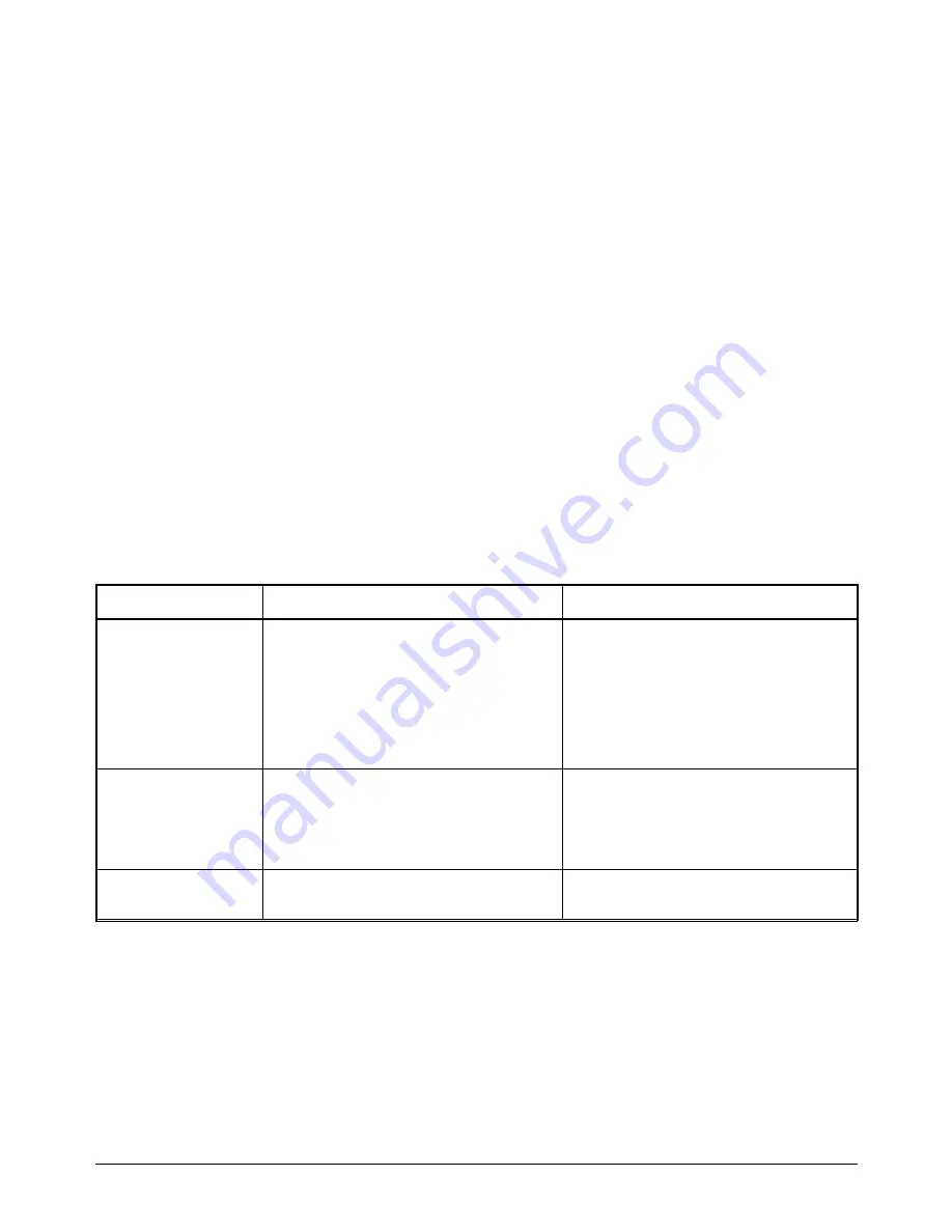
Table B-1 shows some general programming methods for accessing the
HP E1418A registers using different computers.
Table B-1. Register Access
System
Typical Commands
Base Address
External Computer
(over HP-IB to
E1405/E1406
Command Module)
VXI:READ? logical_address, offset
VXI:WRITE logical_address, offset, data
DIAG:PEEK? Bas offset, width
DIAG:POKE Bas offset, width, data
(width must be either 8 or 16)
logical_address = LADDR
offset = register number
Base_addr = 1FC000
16
+ (LADDR
16
* 40
16
)
or
= 2,080,768 + (LADDR * 64)
offset = register number
V/382 Embedded
Computer
READIO (-18, Bas offset)
WRITEIO (-18, Bas offset; data)
(positive select code = byte read or write
negative select code = word read or write)
Base_addr = C000
16
+ (LADDR
16
* 40
16
)
or
= 49,152 + (LADDR * 64)
offset = register number
SICL
iwpoke(Bas offset,data)
iwpeek(Bas offset)
imap(id,I_MAP_VXIDEV,0,0,NULL)
LADDR = HP E1418A Logical Address = 72 = 48
16
Appendix B
HP E1418A Register-Based Programming 120
Содержание E1418A
Страница 6: ...Notes 6 Contents HP E1418A 8 16 Channel D A Converter Module ...
Страница 10: ...Notes 10 HP E1418A User s Manual ...
Страница 12: ...12 HP E1418A User s Manual ...
Страница 105: ...TRIGger 105 HP E1418A SCPI Command Reference Chapter 3 ...
Страница 111: ...Notes HP E1418A Command Quick Reference 111 HP E1418A SCPI Command Reference Chapter 3 ...
Страница 135: ...135 HP E1418A Register Based Programming Appendix B ...
Страница 157: ...Notes 156 HP E1418A Error Messages Appendix C ...
Страница 164: ...Figure D 4 Resistance Calibration Connections CAL Appendix D Voltage Current Output Adjustment 163 ...
Страница 170: ...Notes Appendix D Voltage Current Output Adjustment 169 ...
Страница 174: ...Figure E 1 8 Channel Disassembly 172 Configuration and Disassembly Appendix E ...
Страница 175: ...Figure E 2 16 Channel Disassembly Appendix E Configuration and Disassembly 173 ...
Страница 177: ...Figure E 3 Plug on Channel Locations Figure E 4 Installing Plug on Modules Appendix E Configuration and Disassembly 175 ...
Страница 192: ...Notes 192 HP E1418A 8 16 Channel D A Converter Module Index ...


