background image

1-6

   Compaq Professional Workstation AP550 Maintenance and Service Guide

Memory

8

10

1

11

9

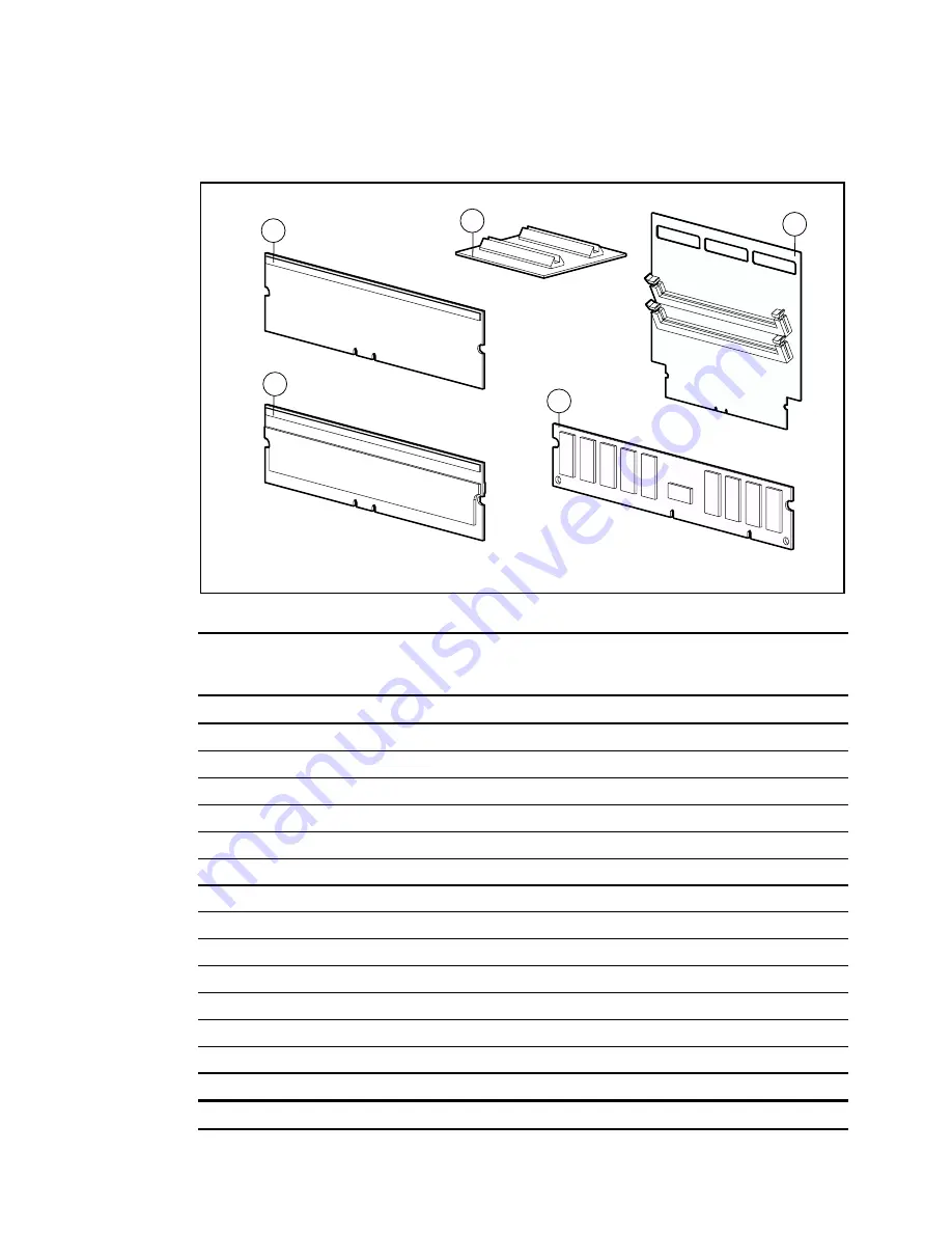
Figure 1-5.  Memory for the Compaq Professional Workstation AP550

Table 1-3

Memory Spare Parts List

Item

Description

Spare Part #

1

64-MB ECC Direct Rambus Inline Memory Modules (RIMM) 600-MHz

157107-001

2

64-MB ECC Direct Rambus Inline Memory Modules (RIMM) 800-MHz

162995-001*

3

128-MB ECC Direct Rambus Inline Memory Modules (RIMM) 600-MHz

158264-001*

4

128-MB ECC Direct Rambus Inline Memory Modules (RIMM) 600-MHz

164539-001*

5

128-MB ECC Direct Rambus Inline Memory Modules (RIMM) 800-MHz

157112-001*

6

256-MB ECC Direct Rambus Inline Memory Modules (RIMM) 600-MHz

161453-001*

7

256-MB ECC Direct Rambus Inline Memory Modules (RIMM) 800-MHz

161454-001*

8

Continuity RIMMs (CRIMMs)

158265-001

9

SDRAM expansion board

158273-001

10

SDRAM expansion board stabilizer card

158276-001

11

64-MB ECC memory modules (Registered 100-MHz SDRAM)

329340-001

12

128-MB ECC memory modules (Registered 100-MHz SDRAM) )

329341-001*

13

256-MB ECC memory modules (Registered 100-MHz SDRAM) )

329343-001*

14

512-MB ECC memory modules (Registered 100-MHz SDRAM) )

329344-001*

Note:

  Parts or components marked with an asterisk (*) are 

not illustrated.

Содержание Deskpro AP550

Страница 1: ...re part number 158279 001 The complete MSG follows these addenda These addenda contain changes to the original document 2000 Compaq Computer Corporation All rights reserved Compaq is registered in the U S Patent and Trademark Office Product names mentioned herein may be trademarks and or registered trademarks of their respective companies First Edition July 2000 ...

Страница 2: ...AGP 2x 4x 163361 001 A Intense3D Wildcat 4110 AGP 2X 166013 001 A Intense3D Wildcat 4210 AGP Pro 202996 001 A Nvidia TNT2 PRO 16 MB SGRAM 179997 001 A ELSA Gloria II AGP 64 MB 174641 001 A Matrox G200 MMS 171975 001 A Graphics adapter DVI i to VGA 202997 001 A Hard Drives 10 GB Ultra ATA Hard Drive 7200 RPM 330520 001 A 20 GB Ultra ATA Hard Drive 7200 RPM 157403 001 A 20 GB Ultra ATA Hard Drive 72...

Страница 3: ...ellaneous Cable Kit CD ROM data 12 5 179048 001 CD ROM data 12 5 105876 001 Diskette drive 15 5 179049 001 CD ROM audio 12 288489 001 Thermal sensor 166785 001 Hard drive CD ROM drive data 14 242947 001 Hard drive data 7 247116 001 Hard drive CD ROM drive data 14 25 242947 008 Diskette drive data 12 247176 003 Hard drive CD ROM drive data 10 247116 002 Y adapter hard drive data 296563 001 179182 0...

Страница 4: ...phics Controller Supported Resolutions Without Multisampling bits per pixel Aspect Ratio 96 128 160 192 4 x 3 1824x1368 65 Hz 1600x1200 75 Hz 1824x1368 65 Hz 1600x1200 75 Hz 5 x 4 1280x1024 85 Hz 1280x1024 85 Hz 1280x1024 85 Hz 1280x1024 85 Hz 16 x 9 2048x1152 70 Hz 1920x1080 75 Hz 2048x1152 70 Hz 1920x1080 75 Hz 16 x 10 1920x1200 70 Hz 1824x1128 75 Hz 1920x1200 70 Hz 1824x1128 75 Hz 5 x 4 Frame S...

Страница 5: ...152 75 Hz 16 x 10 1920 x 1200 75 Hz 1920 x 1200 75 Hz 1920 x 1200 75 Hz 1920 x 1200 75 Hz 5 x 4 Frame Sequential Stereo 1280 x 1024 60 Hz 1280 x 1024 60 Hz 1280 x 1024 60 Hz 1280 x 1024 60 Hz 4 x 3 Frame Sequential Stereo 128 0x 960 60 Hz 1280 x 960 60 Hz 1280 x 960 60 Hz 1280 x 960 60 Hz Supported Resolutions with Multisampling Aspect Ratio 128 bits per pixel 192 bits per pixel 4 x 3 1600 x 1200 ...

Страница 6: ...0 Hz 60 100 Hz 60 80 Hz 60 76 Hz 30 108 kHz 44 76 kHz 64 108 kHz 70 94 kHz 75 95 kHz ELSA Gloria II AGP Graphics Controller Graphics Memory Maximum Colors Supported Resolution Maximum Refresh Rate Memory Dedicated to Texture Support 64 MB 16 7M 640 x 480 800 x 600 1024 x 768 1152 x 864 1280 x 800 1280 x 960 1280 x 1024 1600 x 1000 1600 x 1000 1600 x 1200 1600 x 1280 1600 x 1280 1900 x 1080 1920 x ...

Страница 7: ...135618 001 7 Air Baffle Assembly ...

Страница 8: ...Compaq Professional Workstation AP550 Maintenance and Service Guide ...

Страница 9: ...Professional Workstation AP550 Maintenance and Service Guide First Edition October 1999 Part Number 135618 001 Spare Part Number 158279 001 Compaq Computer Corporation ...

Страница 10: ...mputer Corporation 1999 Compaq Computer Corporation All rights reserved Printed in the U S A The software described in this guide is furnished under a license agreement or nondisclosure agreement The software may be used or copied only in accordance with the terms of the agreement Compaq Compaq Insight Manager ROMPaq QVision NetFlex QuickFind PaqFax registered United States Patent and Trademark Of...

Страница 11: ... List 1 4 Mechanical Components 1 4 System Components 1 5 Memory 1 6 Mass Storage Devices 1 7 Cable Kits 1 8 Graphic Controllers 1 9 Network Controllers 1 10 Input Output Devices 1 11 Software and Miscellaneous 1 12 Documents 1 12 Chapter 2 Service Preliminaries Overview 2 1 Preliminary Warnings and Cautions 2 2 Electrostatic Discharge Information 2 3 Equipment Symbols 2 3 Tools and Software Requi...

Страница 12: ...velock 3 21 Expansion Boards 3 23 Removing an Expansion Board 3 24 Installing an Expansion Board 3 25 Serial Port Cover Connector 3 27 Card Guide 3 28 Memory Modules 3 29 Overview 3 29 RIMM Slot Locations and Configurations 3 30 Removing and Installing RIMMs 3 31 DIMM Location and Configurations 3 34 Removing and Installing DIMMs 3 35 Processor 3 40 Removing a Processor 3 40 Installing an Addition...

Страница 13: ...nfiguration Memory 4 25 Diagnostics Utilities 4 26 Error Codes 4 31 SCSI Error Codes 4 39 Upgrading the ROM 4 42 Local ROM Flash 4 42 Remote ROM Flash 4 43 FailSafe Boot Block ROM 4 43 Fault Management 4 45 SMART III Hard Drive Fault Prediction 4 45 Ultra ATA Integrity Monitoring 4 45 Compaq Insight Manager 4 46 Compaq Management Agents for Workstations 4 46 Compaq Restore CD 4 47 Compaq Diagnosti...

Страница 14: ...e 6 5 Zip Drive 6 5 Chapter 7 Physical and Operating Specifications Overview 7 1 System Unit 7 2 375 W Power Supply 7 8 Diskette Drive 7 9 Zip Drive 7 10 CD ROM Drive 7 14 DVD ROM Drive 7 16 Hard Drives 7 18 Audio System 7 21 Keyboard 7 21 Mouse 7 22 Graphics Controllers 7 23 Network Controller 7 25 RJ 45 Network Cable Specifications 7 25 Chapter 8 External Connectors Overview 8 1 Physical Locatio...

Страница 15: ...o are knowledgeable of the procedures precautions and hazards associated with equipment containing hazardous energy circuits Symbols in Text These symbols may be found in the text of this guide They have the following meanings WARNING Text set off in this manner indicates that failure to follow directions in the warning could result in bodily harm or loss of life CAUTION Text set off in this manne...

Страница 16: ... specified in these procedures Because of the complexity of the individual boards and subassemblies do not attempt to make repairs at the component level or to make modifications to any printed wiring board Improper repairs could create conditions that are hazardous WARNING To reduce the risk of electric shock or damage to the equipment If the system has multiple power supplies disconnect power fr...

Страница 17: ...y and comfort guide All documents are presented in PDF file format with an easy to use graphical interface When the CD is inserted into the CD ROM the CD automatically detects the operating system language and loads the corresponding language files if available Compaq Download Facility Call 1 281 518 1418 Telephone Numbers For the name of your nearest Compaq authorized reseller In the United State...

Страница 18: ...Chapter 1 Illustrated Parts Catalog This chapter provides an illustrated parts breakdown and a reference for spare parts for the Compaq Professional Workstation AP550 ...

Страница 19: ...1 2 Compaq Professional Workstation AP550 Maintenance and Service Guide Overview Mechanical Parts Figure 1 1 Exploded view for the Compaq Professional Workstation AP550 mechanical parts ...

Страница 20: ...Illustrated Parts Catalog 1 3 System Components Figure 1 2 Exploded view for the Compaq Professional Workstation AP550 system components ...

Страница 21: ... 2 3 Figure 1 3 Mechanical components for the Compaq Professional Workstation AP550 Table 1 1 Mechanical Components Spare Parts List Item Description Spare Part 1 Workstation access panel 137384 001 2 Chassis 164540 001 3 Front bezel 158268 001 Note Parts or components marked with an asterisk are not illustrated ...

Страница 22: ...e bus 163363 001 3 Battery 153099 001 4 System board for the Compaq Professional Workstation AP550 158272 001 5 Terminator board for secondary processor slot 158271 001 6 Lock security bracket 199109 001 7 Loud speaker 164416 001 8 Power switch and LEDs with cable 166925 001 9 375 W power supply with Power Factor Correction PFC 128399 001 10 Auxiliary fan standard on the Compaq Professional Workst...

Страница 23: ...600 MHz 164539 001 5 128 MB ECC Direct Rambus Inline Memory Modules RIMM 800 MHz 157112 001 6 256 MB ECC Direct Rambus Inline Memory Modules RIMM 600 MHz 161453 001 7 256 MB ECC Direct Rambus Inline Memory Modules RIMM 800 MHz 161454 001 8 Continuity RIMMs CRIMMs 158265 001 9 SDRAM expansion board 158273 001 10 SDRAM expansion board stabilizer card 158276 001 11 64 MB ECC memory modules Registered...

Страница 24: ...1 001 2 9 GB Ultra3 SCSI hard drive 10 000 rpm 160062 001 3 18 GB Ultra3 SCSI hard drive 10 000 rpm 160063 001 4 10 GB Ultra ATA 66 IDE hard drive 7 200 rpm 135364 001 5 18 GB Ultra3 SCSI hard drive 7 200 rpm 153650 001 6 72 TrueX CD ROM drive optional 134195 001 7 1 44 MB diskette drive 158266 001 8 40X CD ROM drive 400807 001 9 250 MB Zip Drive optional 125776 001 10 100 MB Zip Drive 401624 001 ...

Страница 25: ...s Spare Parts List Item Description Spare Part 1 Miscellaneous Cable Kit 166838 001 288489 002 247116 001 242947 001 166879 001 2 SCSI LVD 3 device twisted pair cable 158277 001 3 Serial port cover connector 158274 001 4 NIC Wake on LAN cable 166974 001 5 Power cord 121258 001 6 Video cable 60 POS 164415 001 Note Parts or components marked with an asterisk are not illustrated ...

Страница 26: ...re Parts List Item Description Spare Part 1 Matrox Productiva G100 Multi Monitor 101239 001 2 Matrox G400 16 MB 4X AGP 2D 400437 001 3 ELSA Synergy II 32 MB 4X AGP entry 3D 146140 001 4 3Dlabs Oxygen GVX1 AGP mid 3D 146141 001 5 3Dlabs Oxygen GVX1 PCI mid 3D 159629 001 6 PowerStorm 600 enh 3D 122926 001 Note Parts or components marked with an asterisk are not illustrated ...

Страница 27: ...7 Network Controllers Spare Parts List Item Description Spare Part 1 Compaq NC3121 Fast Ethernet NIC PCI 10 100 Wake on LAN 323556 001 2 Netelligent 16 4 TR PCI UTP STP Controller 268010 001 3 Compaq NC3120 Fast Ethernet NIC PCI 10 100 317606 001 4 Compaq NC3123 Fast Ethernet NIC PCI 10 100 Wake on LAN 174831 001 Note Parts or components marked with an asterisk are not illustrated ...

Страница 28: ...itor Opal without protective panel TC095 WW 307906 001 10 TFT8000 flat panel monitor Opal with protective panel TC095 WW 307931 xxx 11 TFT8000 flat panel monitor Carbon without protective panel TC095 WW 307932 xxx 12 TFT8000 flat panel monitor Carbon with protective panel TC095 WW 307935 xxx 13 TFT5000S Flat Panel Color EMEA 104751 021 14 TFT5000S Flat Panel Color outside EMEA 122729 xx1 15 V1000 ...

Страница 29: ... 3 5 to 5 25 inch hard drive mounting bracket 243231 001 4 3 5 to 5 25 inch height mounting bracket for use in bays 1 and 2 only 243230 002 5 Shipping box with buns US 166990 001 6 Shipping box with buns INTL 166990 002 Note Parts or components marked with an asterisk are not illustrated Documents Table 1 10 Document Spare Parts List Item Description Spare Part 1 Maintenance and Service Guide 1582...

Страница 30: ...ng service considerations Preliminary warnings and cautions Electrostatic discharge information Equipment symbols Tools and software requirements Warranty information IMPORTANT Adherence to the procedures and precautions described in this chapter is essential for proper service ...

Страница 31: ...mblies no one should attempt to make repairs at the component level or to make modifications to any printed wiring board Improper repairs can create a safety hazard CAUTION The power supply in the Compaq Professional Workstation AP550 has an auxiliary power section This section is always active as long as the unit is plugged into a live AC outlet Be sure to turn off the switch and unplug the power...

Страница 32: ...ce drives PCB assembly side down Use conductive field service tools Equipment Symbols The following symbols are located on applicable components of the workstation and should be observed when servicing the workstation to avoid personal injury or damage to the components WARNING Any surface or area of the equipment marked with these symbols indicates the presence of a hot surface or hot component I...

Страница 33: ...ty by applying it to critical system components before they fail This warranty ensures that when you receive notification of a prefailure condition through Compaq Insight Manager or the Windows NT Event Log the component is replaced under warranty NOTE For more information about Compaq Insight Manager see Chapter 4 The Pre Failure Warranty covers the following workstation components Y SCSI hard dr...

Страница 34: ...vides subassembly module level removal and replacement procedures for the Compaq Professional Workstation AP550 After completing all necessary removal and replacement procedures run the Compaq Setup and Diagnostics program to verify that all components are operating properly ...

Страница 35: ...hassis 2 For asset control the serial number is embedded in the EPROM on the system board If the system board is replaced with a spare part from Compaq an invalid serial number condition will be reported during Power On Self Test POST To clear the condition reenter the original serial number through Computer Setup NOTE POST recognizes the serial number as a valid number if a system board from anot...

Страница 36: ... the grounded AC outlet 3 Turn off all peripheral devices and disconnect cables from the rear of the workstation NOTE See Chapter 2 for more information on preparing the workstation for service Cable Lock The workstation comes standard with a cable lock provision for attaching a padlock and or cable lock If installed the locks must be removed before you can access internal components To remove the...

Страница 37: ... as previously shown CAUTION Before removing the workstation access panel ensure that the workstation is turned off all cables are disconnected from the back of the workstation and the power cord is disconnected from the grounded AC outlet 2 Loosen the two thumbscrews that secure the workstation access panel to the workstation chassis Figure 3 3 Loosening the side workstation access panel thumbscr...

Страница 38: ...Procedures 3 5 3 Slide the workstation access panel back about 1 inch 2 5 cm then lift it off the workstation Figure 3 4 Removing the workstation access panel To replace the workstation access panel reverse the above procedure ...

Страница 39: ... from the back of the workstation and the power cord is disconnected from the grounded AC outlet 2 Remove the workstation access panel 3 Press in on the two release tabs 1 then rotate the front bezel away from the chassis to remove it from the workstation 2 2 2 1 Figure 3 5 Removing the front bezel To replace the front bezel reverse the above procedure NOTE When replacing the front bezel be sure t...

Страница 40: ...disconnected from the grounded AC outlet 2 Remove the side workstation access panel 3 Remove the front bezel 4 Gently pull the subpanel with the bezel blank secured in it away from the front bezel and then remove the bezel blank CAUTION Hold the subpanel straight when you pull it away from the front bezel Pulling at an angle could damage the pins that align the subpanel within the front bezel Figu...

Страница 41: ...ce Guide CAUTION When replacing the subpanel be sure the aligning pins and any remaining bezel blanks are in the proper orientation to prevent damage to the alignment pins DESKTOP TOWER KEY TOWER DESKTOP Figure 3 7 Identifying the subpanel keyed alignment positions ...

Страница 42: ...t CD ROM optional drive 1 6 inch 3 3 5 inch bay Third height Standard 1 44 MB diskette drive 1 0 inch 4 3 5 inch bay Third height Optional hard drive 1 0 inch 5 3 5 inch bay Third height Standard hard drive You may install either a third height or half height drive into a half height bay Use a drive adapter to mount a high density diskette drive into a 5 25 inch bay NOTE Compaq does not support mi...

Страница 43: ...screws installed in the front of the workstation chassis behind the front bezel Some options use 5 25 M3 metric screws and some use HD 6 32 The Compaq supplied metric screws are black NOTE For optimal performance connect hard drives to the primary controller Connect expansion devices such as IDE CD ROM tape and diskette drives to the secondary controller 6 32 M3 Figure 3 9 Identifying the metric M...

Страница 44: ...ving the workstation access panel ensure that the workstation is turned off all cables are disconnected from the back of the workstation and the power cord is disconnected from the grounded AC outlet 2 Remove the workstation access panel 3 Remove the front bezel 4 Disconnect the power 1 and data 2 cables from the back of the hard drive 1 2 Figure 3 10 Disconnecting the hard drive cables ...

Страница 45: ...lock the hard drive Figure 3 11 Releasing the hard drive by raising the drivelock 6 Hold the drivelock up while you push the drive from the rear and remove it from the front of the drive bay 1 1 2 2 Figure 3 12 Removing a 3 5 inch hard drive 7 Remove the two guide screws from each side of the drive 2 ...

Страница 46: ... hard drive option kit 3 5 Inch Drive with 5 25 Inch Drive Adapter To remove a 3 5 inch drive with a 5 25 inch drive adapter 166923 001 1 Perform the steps in the Service Preparations section as previously shown CAUTION Before removing the workstation access panel ensure that the workstation is turned off all cables are disconnected from the back of the workstation and the power cord is disconnect...

Страница 47: ...al Workstation AP550 Maintenance and Service Guide 6 Hold the drivelock up while you push the drive from the rear and remove it from the front of the drive bay Figure 3 14 Removing a 3 5 inch drive from a 5 25 inch drive bay ...

Страница 48: ...1 1 2 4 3 5 4 Figure 3 15 Removing a 3 5 inch drive from the 5 25 inch drive adapter To replace the drive reverse the above procedure IMPORTANT The primary 3 5 inch diskette drive should only be installed into bay 3 NOTE If you are installing a second 3 5 inch diskette drive into bay 1 or 2 for the first time you must use a special adapter bracket See Chapter 1 for the spare part number If you are...

Страница 49: ...N Before removing the workstation access panel ensure that the workstation is turned off all cables are disconnected from the back of the workstation and the power cord is disconnected from the grounded AC outlet 2 Remove the workstation access panel 3 Remove the front bezel 4 Disconnect the power 1 data 2 and audio 3 cables from the back of the hard drive 1 2 3 Figure 3 16 Disconnecting the cable...

Страница 50: ...osition while you push the hard drive from the rear and remove it from the front of the drive bay Figure 3 18 Removing a 5 25 inch drive To replace the hard drive 1 Install two M3 guide screws Figure 3 9 into the bottom holes on each side of the replacement drive making sure the guide screws line up with the guide slots 2 Slide the drive into the drive bay until it snaps into place ...

Страница 51: ...ontroller requires a unique SCSI ID 0 7 or 8 15 for each SCSI device installed The controller identifies a SCSI device by its SCSI ID number rather than its location Moving a SCSI device from one position to another on the SCSI chain does not affect communication between the controller and the device SCSI ID 0 is reserved for the primary hard drive SCSI ID 7 is reserved for the controller SCSI IDs...

Страница 52: ...controller Wide Ultra can only be mixed with Wide Ultra SCSI devices Narrow can only be mixed with narrow SCSI devices Do not mix Wide Ultra2 and Ultra3 with other types of SCSI devices Wide Ultra2 and Ultra3 SCSI devices can only be mixed with each other and can coexist in any combination If two controllers are installed each may use SCSI devices having widths and speeds different from the other ...

Страница 53: ...d has a terminator 1 on one end The cable end connects to the internal LVD SE connector on the system board with the remaining three connectors connecting to the devices in the drive bays 1 Figure 3 19 Multi mode cable SCSI with terminator NOTE The multi mode cable included with your workstation may differ from the one pictured For additional information about installing optional SCSI devices refe...

Страница 54: ...es are disconnected from the back of the workstation and the power cord is disconnected from the grounded AC outlet 2 Remove the workstation access panel 3 Remove the front bezel 4 Remove all drives from the computer 5 Lift the side of each drivelock nearest you and push it toward the front of the drive cage 1 then snap the tabs out of the holes in the drive cage 2 CAUTION The spring under the dri...

Страница 55: ...rt the left side of the drivelock with the rounded tabs into the slots on the drive cage 1 2 Place the washer on the middle tab on the underside of the drivelock 3 Compress the spring 2 and then lower the drivelock onto the drive cage until it snaps into place 3 3 3 1 2 Figure 3 21 Reinstalling the drivelock ...

Страница 56: ...ctors populate full length boards See the corresponding table for component names 1 2 3 4 5 Figure 3 22 Overview of the expansion board slots Table 3 3 Expansion Board Slots Reference Description 1 PCI expansion board slot 2 PCI expansion board slot 3 PCI expansion board slot 4 PCI expansion board slot 5 Accelerated Graphics Port AGP 4X Pro slot ...

Страница 57: ...AC outlet 2 Remove the workstation access panel 3 Disconnect any cables from the expansion board 4 Remove the expansion board retaining screw 5 Hold the board at each end and carefully rock it back and forth until the connectors pull free from the slot Be sure not to scrape the board against other components Figure 3 23 Removing an expansion board 6 Store the board in antistatic packaging 7 Instal...

Страница 58: ...d disconnect the power cord from the grounded AC outlet and the back of the workstation Disconnect the network cable and any external devices from the system 2 Remove the workstation access panel and locate the correct vacant slot in the workstation chassis 3 Remove the screw securing the expansion slot cover and then remove the slot cover as illustrated Figure 3 24 Removing the screw and expansio...

Страница 59: ...pansion board press firmly on the board so that the whole connector seats properly in the expansion board slot NOTE If you are installing a full length PCI expansion board make sure the board is engaged with the card guide 2 Replace the screw at the side of the expansion slot 3 Replace the workstation access panel 4 Connect external cables to the installed board if needed 5 Plug the network cable ...

Страница 60: ...nd the power cord is disconnected from the grounded AC outlet 2 Remove the workstation access panel 3 Rotate the workstation to the desktop position 4 Unplug the serial port cover connector from the system board Figure 3 26 Removing the serial port cover connector 5 Remove the screw holding the serial port cover connector to the chassis and lift the plate out of the chassis To replace the serial p...

Страница 61: ... workstation is turned off all cables are disconnected from the back of the workstation and the power cord is disconnected from the grounded AC outlet 2 Remove the workstation access panel 3 Remove any full length expansion boards 4 Push down on the two tabs on the top of the card guide 1 5 While holding the tabs down remove the card guide from the chassis 2 2 1 Figure 3 27 Removing the card guide...

Страница 62: ...as four RIMM sockets on the system board two per memory channel to support a maximum of 2 gigabyte of memory with 256 megabit Direct RDRAM technology RIMM modules must be installed in pairs across both channels for example one module in socket XMM1 and the other module in socket XMM3 Each pair of memory modules must be of the same type speed and size This information can be found on the label affi...

Страница 63: ...MM1 and XMM2 Channel A and XMM3 and XMM4 Channel B 1 3 4 2 Figure 3 28 RIMM sockets must be populated in pairs Table 3 4 RIMM Slot Locations Identifier Component Memory Channel 1 RIMM Slot XMM2 Channel A 2 RIMM Slot XMM1 Channel A 3 RIMM Slot XMM4 Channel B 4 RIMM Slot XMM3 Channel B Table 3 5 RIMM Installation Configurations Memory Channel A Memory Channel B RIMM Pairs RIMM Slot XMM1 RIMM Slot XM...

Страница 64: ...is fully inserted and properly seated Populate unused RIMM sockets with a Continuity RIMM CRIMM If CRIMMs are not in the empty RIMM sockets the system will not boot Install RIMM modules in pairs across both channels RIMM sockets must be populated in the following order XMM1 and XMM3 then XMM2 and XMM4 Do not mix RIMMs and DIMMs on the same system board The system will not boot if RIMMs and DIMMs a...

Страница 65: ...cables are disconnected from the back of the workstation and the power cord is disconnected from the grounded AC outlet 2 Remove the workstation access panel WARNING RIMMs can reach a temperature of 212 F 100 C in a matter of minutes Caution should be exercised whenever removing or replacing these components 3 Press outward on both latches of the RIMM at the same time 1 This releases the module an...

Страница 66: ... temperature of 212 F 100 C in a matter of minutes Caution should be exercised whenever removing or replacing these components CAUTION When handling a RIMM be careful not to touch any of the contacts Doing so may damage the module 3 A RIMM can be installed only one way Be sure to match the two key slots on the RIMM with the tab on the RIMM socket Push the RIMM down into the RIMM socket ensuring th...

Страница 67: ...g and Correcting ECC Dual Inline Memory Modules DIMMs Figure 3 30 Overview of two SDRAM expansion boards installed in alternating RIMM sockets containing one DIMM on each board The following configuration guidelines must be followed when replacing SDRAM expansion boards Table 3 7 SDRAM Expansion Boards Configurations Memory Channel RIMM Slot XMM1 RIMM Slot XMM2 RIMM Slot XMM3 RIMM Slot XMM4 Channe...

Страница 68: ...d 100 MHz Error Checking and Correcting ECC DIMMs DO NOT INSTALL DIMMs THAT DO NOT SUPPORT ERROR CHECKING AND CORRECTING ECC SDRAM expansion boards must be installed in pairs populating the RIMM sockets in the following order XMM1 and XMM3 Only two SDRAM expansion boards are supported Each SDRAM expansion board supports up to two DIMMs Total system support is up to four DIMMs providing up to 2 GB ...

Страница 69: ...followed when installing SDRAM expansion boards or the workstation will not function CAUTION RIMM sockets have gold metal contacts When upgrading memory it is important to use SDRAM expansion boards with gold metal contacts not tin lead to prevent corrosion and or oxidation resulting from having incompatible metals in contact with each other CAUTION When handling a memory module be careful not to ...

Страница 70: ... install a DIMM memory module IMPORTANT Before installing a SDRAM expansion board read the previous section Important Guidelines for DIMM Installation 1 Perform the steps in the Service Preparations section as previously shown CAUTION Before removing the workstation access panel ensure that the workstation is turned off all cables are disconnected from the back of the workstation and the power cor...

Страница 71: ...ion board 5 Install the SDRAM expansion board in the appropriate RIMM socket on the system board Follow the correct configuration guidelines in Table 3 8 NOTE The SDRAM expansion board with an attached DIMM can be installed only one way Be sure to match the two key slots on the SDRAM expansion board with the tab on the RIMM socket Push the SDRAM expansion board down into the RIMM socket ensuring t...

Страница 72: ...en attaching the workstation access panel assure the SDRAM expansion board stabilizer card attached to the side access panel engages with the SDRAM expansion boards holding the boards in an upright position NOTE The system recognizes memory upgrades and automatically reconfigures the workstation ...

Страница 73: ... disconnected from the grounded AC outlet 2 Remove the workstation access panel CAUTION If two processors are installed and the primary processor needs replacing the secondary processor must be removed before removing the primary processor Failure to do so may cause damage to the primary processor 3 Pull out the retaining tabs on each side of the processor 1 and then lift the processor out of the ...

Страница 74: ...or incorrectly may cause damage to the system board Compaq recommends that you have a Compaq authorized reseller or service provider install the processor If you plan to install a processor yourself carefully read all the instructions before you begin IMPORTANT An empty processor slot must contain a terminator board To install a second Pentium III processor 1 Turn off the workstation and disconnec...

Страница 75: ...slot Figure 3 37 Installing a second processor heatsink assembly 6 Push the processor heatsink into the secondary processor slot until it locks firmly into place IMPORTANT Do not mix processors The second processor must be the same speed cache size and type as the existing processor Reassemble the workstation and connect the power cord to the grounded AC outlet and to the workstation IMPORTANT Be ...

Страница 76: ...usly shown CAUTION Before removing the workstation access panel ensure that the workstation is turned off all cables are disconnected from the back of the workstation and the power cord is disconnected from the grounded AC outlet 2 Remove the workstation side access panel 3 Push the retaining tabs on each side of the processor outward and then lift the processor out of the socket 4 Slide the metal...

Страница 77: ...move it from the heatsink 2 2 Figure 3 39 Removing the metal clip and processor from the heatsink To install a new processor heatsink reverse the above procedure NOTE Before installing a processor be sure the release latches are in the locked out position This will cause the latches to click into place when the processor is properly seated ...

Страница 78: ...ure that the workstation is turned off all cables are disconnected from the back of the workstation and the power cord is disconnected from the grounded AC outlet 2 Remove the workstation access panel 3 Remove the graphics board 4 Remove the speaker 5 Remove the processor 6 Unscrew the clay nuts 1 that secure the processor guide rails to the system board using a T15 torx drive 7 Remove the guide r...

Страница 79: ... that the workstation is turned off all cables are disconnected from the back of the workstation and the power cord is disconnected from the grounded AC outlet 2 Remove the workstation access panel 3 Disconnect the speaker cable from the system board 4 Remove the four screws that secure the speaker to the side of the drive cage 1 and then remove the speaker 2 2 1 Figure 3 41 Removing the speaker T...

Страница 80: ...nnected from the back of the workstation and the power cord is disconnected from the grounded AC outlet 2 Remove the workstation access panel 3 Unplug the fan from the system board 4 Remove the four screws that hold the fan to the chassis 1 and lift the fan out of the unit 2 5 Remove the four push lock fasteners 3 from the fan assembly 1 1 2 3 Figure 3 42 Removing the system board fan To replace t...

Страница 81: ...ons section as previously shown CAUTION Before removing the workstation access panel ensure that the workstation is turned off all cables are disconnected from the back of the workstation and the power cord is disconnected from the grounded AC outlet 2 Remove the workstation access panel 3 Disconnect all power cables from the mass storage devices and the system board ...

Страница 82: ...upply reverse the preceding procedure WARNING This equipment is designed for connection to a grounded earthed outlet To reduce the risk of electrical shock damage to the equipment or loss of the data do not disable this feature The grounding type plug is an important safety feature WARNING Only qualified personnel should perform this procedure Do not reconnect power to the computer until the compu...

Страница 83: ...tion access panel ensure that the workstation is turned off all cables are disconnected from the back of the workstation and the power cord is disconnected from the grounded AC outlet 2 Remove the workstation access panel 3 Disconnect the power LED cable from the system board 1 4 Push the release tab toward the drive bays 2 and then remove the power switch from the chassis 3 3 1 2 Figure 3 44 Disc...

Страница 84: ...ion as previously shown CAUTION Before removing the workstation access panel ensure that the workstation is turned off all cables are disconnected from the back of the workstation and the power cord is disconnected from the grounded AC outlet 2 Remove the workstation access panel 3 With the workstation in the desktop position remove the speaker 4 Remove all expansion boards 5 Disconnect all cables...

Страница 85: ... the rear of the board up 3 then lift the board up and out of the chassis 4 1 2 1 1 3 4 Figure 3 45 Removing the system board from the chassis To install a new system board reverse the above procedure CAUTION Damage to the system board could result if all the power cables are not properly reconnected to the system board NOTE When installing the system board properly align the board in the chassis ...

Страница 86: ...ower cord is disconnected from the grounded AC outlet 2 Remove the workstation access panel 3 Remove all expansion boards 4 Remove the speaker 5 Remove the power supply 6 Disconnect all cables that are attached to the system board 7 Remove the system board 8 Remove the I O panel from the back of the chassis Figure 3 46 Removing the I O panel To replace the I O panel reverse the above procedure CAU...

Страница 87: ...ricity by briefly touching a grounded metal object NOTE It is important to make a diagnostics diskette before you install a new battery Instructions for creating and using the Compaq Diagnostic Diskette are located on the Compaq website www compaq com To replace the lithium battery 153099 001 1 Perform the steps in the Service Preparations section as previously shown CAUTION Before removing the wo...

Страница 88: ...he holder Figure 3 48 Removing the battery To replace the battery slide the replacement battery into position with the positive side up IMPORTANT Positive polarity should be positioned up NOTE The battery holder automatically secures the battery in the proper position ...

Страница 89: ... from the grounded AC outlet 2 Remove the workstation access panel 3 Remove the front bezel 4 Disconnect all power and data cables from the hard drives in the 5 25 inch drive bays 5 Remove the drives from the 5 25 inch drive bays by lifting the drivelock Figure 3 49 Releasing the drives by lifting the drivelock 6 Push the drives from the rear and remove them from the front of the drive bay CAUTION...

Страница 90: ...he drives are properly inserted the drivelock will secure them IMPORTANT The diskette drive should always be placed in the bay nearest the top of the chassis in the desktop configuration for proper drive clearance and access Figure 3 50 Installing a drive in the desktop configuration 8 Reconnect the power and data cables to the drives ...

Страница 91: ...damage the pins that align it within the front bezel 10 Replace the subpanel and front bezel ensuring the subpanel and front bezel align properly with the alignment tabs CAUTION When replacing the subpanel be sure the aligning pins and any remaining bezel blanks are in the proper orientation to prevent damage to the alignment pins See Figure 3 7 for the subpanel keyed alignment positions 11 Reasse...

Страница 92: ...ded AC outlet 2 Remove the workstation access panel 3 Remove the front bezel 4 Disconnect the power and data cables from each drive in the 5 25 inch drive bays 5 Remove each drive from the 5 25 inch drive bays by pressing the drivelock release button Figure 3 52 Releasing the drives with the drivelock release button 6 Push the drives from the rear to remove them from the front of the drive bay CAU...

Страница 93: ...drive bay When the drives are properly inserted the drivelock will secure them IMPORTANT For proper placement within the chassis the diskette drive should always be placed in bay three the bay nearest the internal 3 5 inch drives Figure 3 53 Installing a drive in the minitower configuration 8 Reconnect the power and data cables to each drive ...

Страница 94: ... a desktop 1 to a minitower 2 10 Replace the subpanel and front bezel ensuring the subpanel and front bezel align properly with the alignment tabs CAUTION When replacing the subpanel be sure the aligning pins and any remaining bezel blanks are in the proper orientation to prevent damage to the alignment pins See Figure 3 7 for the subpanel keyed alignment positions 11 Reassemble the workstation NO...

Страница 95: ...T Troubleshooting Minor Problems Computer Setup and Diagnostics Utilities Clearing Configuration Memory Diagnostic Utilities Error Codes ROMPaq Fault Management Compaq Insight Manager Compaq Management Agents for Workstations Compaq Restore CD Compaq Diagnostics for Windows NT IMPORTANT Adherence to the procedures and precautions described in this chapter is essential for proper service ...

Страница 96: ...ler Diskette drives IDE CD ROM drive Hard drives Processor Controllers POST also detects the type of SCSI mass storage devices that are installed in the workstation NOTE If the Power On Password is set a key icon appears on the screen while POST is running You will need to enter the password before continuing See Chapter 5 for information on deleting or bypassing the Power On Password If POST find...

Страница 97: ...ps L Long S Short Probable Source of Problem Recommended Action 101 ROM Error System ROM checksum Contact your Compaq authorized service provider 101 Option ROM Checksum Error Option ROM checksum Contact your Compaq authorized service provider 102 System Board Failure DMA timers and so forth Contact your Compaq authorized service provider 103 System Board Failure Hardware component Replace the Exp...

Страница 98: ...instructions Clear the configuration memory Press F1 and save changes If problem persists replace the CMOS backup battery 163 Time Date Not Set 2S Invalid time or date in configuration memory RTC real time clock battery may need to be replaced Battery life is approximately 5 years CMOS jumper may not be properly installed Set the date and time under Control Panel Run Computer Setup or Windows NT W...

Страница 99: ... Code XX Memory Module Sockets s XX A specific error has occurred in a RDRAM device installed in the identified socket Remove the RIMM device 301 Keyboard Error None Keyboard failure Check to see if a key is stuck Reconnect the keyboard with the computer turned off Replace the keyboard if necessary 303 Keyboard Controller Error None I O board keyboard controller Reconnect the keyboard with compute...

Страница 100: ...t connected to the system board Reattach chassis fan to the system board 1720 SMART Hard Drive detects imminent failure IDE hard drive s Contact your Compaq authorized service provider 1721 SMART SCSI Hard Drive Detects Imminent Failure SCSI hard drive s Contact your Compaq authorized service provider 1771 Primary Disk Port Address Assignment Conflict IDE configuration Run Computer Setup 1772 Seco...

Страница 101: ...792 Secondary Disk Controller Failure None IDE circuitry failure Contact your Compaq authorized service provider 1793 Secondary Controller or Disk Failure None CD ROM interface Run the Diagnostics utility XX000Y ZZ Parity Check 2 None Parity RAM failure Run the Setup and Diagnostics utilities Fixed Disk Parameter Table or BIOS Error System Halted 3L Configuration or hardware failure Run the Setup ...

Страница 102: ... a ROMPaq diskette 1800 Temperature alert The system is too hot Turn off the workstation and let it cool off If the condition persists run Diagnostics to get more information and contact your Compaq authorized service provider 1801 Microcode Patch Error Missing or invalid Processor Microcode Patch Please contact Compaq Computer Corporation or Compaq website at www compaq com for a new ROM BIOS to ...

Страница 103: ...ve all printer drivers been installed for each application Was a nonbootable diskette loaded in the diskette drive at power up Was a bootable compact disc in the CD ROM drive at power up Check all switch and jumper settings Are RIMMs and DIMMs mixed on the same system board The system will not boot if there is a mixture of RIMMs and DIMMs on the system board Are CRIMMs installed in the unpopulated...

Страница 104: ... properly or is defective Be sure that the board is fully inserted or remove the PCI board that was just installed Computer does not automatically display the date and time The real time clock RTC battery may need to be replaced Computer powered off automatically The unit temperature may have been exceeded Check the fan for function and blockage Insufficient power to the components Both power supp...

Страница 105: ... the diskette Writing to the wrong drive Check the drive letter in the path statement Not enough space is left on the diskette Use another diskette to write the information Diskette write control is disabled Check the security feature settings Diskette drive cannot read a diskette Diskette is not formatted Format the diskette Using the wrong diskette type for the drive type Use a diskette that is ...

Страница 106: ... be sure that the monitor can accept the same sweep rate as the resolution chosen Check that the graphics adapter is fully and properly inserted in the PCI or AGP Pro slot Graphics colors are wrong If the BNC cable is used make sure that the Red Green and Blue BNC cables are connected to the corresponding monitor connectors Be sure the monitor s RGB inputs are set to 75 ohms Characters are dim Adj...

Страница 107: ... Num Lock key is on Press the Num Lock key The Num Lock key light should not be on when using the arrow keys Printer Problems Table 4 5 Solutions for Printer Problems Problem Possible Solution Printer will not print Printer is not turned on and online Turn the printer on and be sure it is online The correct printer drivers for the application are not installed Install the correct printer drivers f...

Страница 108: ...rs Hard disk has bad sectors or has failed Use a utility to locate and block usage of bad sectors If necessary reformat the hard disk Disk transaction problem Either the directory structure is bad or there is a problem with a file When using Windows NT Workstation 4 0 run Disk Administrator At the Start menu highlight Programs and select Administrative Tools Drive not found Cable could be loose Ch...

Страница 109: ...rd and choose a basic configuration that does not cause a resource conflict The cables for the new external device are loose or the power cables are unplugged Check all cables The power switch for the new external device is not turned on Turn off the workstation turn on the external device then turn on the workstation to integrate the new device If the drive is a secondary drive that has just been...

Страница 110: ...M boot is not enabled through the Computer Setup utility Run the Computer Setup utility and set the drive priorities Be sure that drive cabling and jumpers are set correctly Cannot eject compact disc CD is not properly seated in the drive Turn off the workstation insert a thin metal rod into the emergency eject hole and push firmly a straightened paper clip can be used Slowly pull the tray out fro...

Страница 111: ... error during operation The system has run out of memory for the application Check memory requirements for the application or install additional memory Unit is powered on but no video is being displayed to the screen and the power LED is blinking red The memory configuration RIMMs or SDRAM board is not installed correctly preventing the unit from booting See the Memory Modules section in Chapter 3...

Страница 112: ...station without the network drivers using a system boot diskette and reconfigure the network controller Diagnostics reports a failure 1 The cable is not securely connected 2 The cable is attached to the incorrect connector 3 There is a problem with the cable or a device at the other end of the cable 4 The network controller is defective 5 Network controller interrupt or memory overlaps the interru...

Страница 113: ...king when an expansion board was installed 1 Network drivers are not loaded or driver parameters do not match the current configuration 2 The cable is not securely connected 3 The network controller interrupt or memory overlaps the interrupt or memory of another expansion board 4 The network controller requires drivers 5 The files containing the network drivers are corrupted 1 Be sure the network ...

Страница 114: ...evice 3 Replace the network controller or the system board Audio Hardware Conflicts Hardware conflicts occur when two or more peripheral devices contend for the same signal lines or channels Conflicts between the audio interface and another peripheral device may be due to the settings of the base I O addresses interrupts or DMA channels The audio interface typically has the following settings Base...

Страница 115: ...T Y Running Diagnostic Utilities for Error Codes Explanations and procedures for each utility are included in this chapter The Setup and Diagnostics utilities should be run in the following instances When a system configuration error is detected during the Power On Self Test POST To change the factory default settings for some of the workstation features To change the system configuration which is...

Страница 116: ...ain to access the utility NOTE The F12 key initiates Network Service Boot for Remote System Installation The Computer Setup menu appears with the following menu headings File Storage Security Power and Advanced See the Computer Setup table Table 4 12 for a description of the features available in Computer Setup 3 Press the arrow keys or the Tab key to select the option you want and then press Ente...

Страница 117: ...TE ATAPI devices CD ROM tape are listed as ATAPI devices Select Storage then select IDE Devices Set hard drive to Ultra DMA Ultra ATA EDMA or PIO mode operation Select Storage for the IDE Drive Timing Specify the order of the hard drive between embedded SCSI IDE and installed third party hard drive controllers Select Storage then select Hard Drive Order Enable disable IDE drive translation Select ...

Страница 118: ...s invalid Select Security then select System IDs Set the POST mode QuickBoot and enable disable POST messages Select Advanced then select Power On Self Test Set resources for onboard system devices serial port parallel port and so forth Select Advanced then select Onboard Devices View the currently installed PCI devices and their IRQ settings and or reconfigure IRQ settings for these devices or di...

Страница 119: ...emoval of expansion boards If the workstation s configuration memory becomes corrupted it is necessary to clear the configuration memory 1 Turn off the workstation and any external devices and disconnect the power cord from the grounded AC outlet 2 Disconnect the keyboard monitor network cable and any other external devices connected to the workstation WARNING To reduce the risk of personal injury...

Страница 120: ... will need to reset your passwords and any special system setups Diagnostics Utilities You must create a diagnostics diskette as soon as you begin to use the workstation This is a bootable diskette that allows you to test and inspect the hardware outside the operating system environmentally running the Computer Checkup TEST or View System Information INSPECT diagnostic programs Another Compaq diag...

Страница 121: ...vides maximum testing of each device with minimal prompts You can choose how many times to run the tests to stop on errors or to print or file an error log Prompted Diagnostics Allows maximum control over the device testing process You can choose attended or unattended testing stop on errors or print or file an error log The TEST option which may vary by product checks the following CPU main syste...

Страница 122: ...displayed again If the list is incorrect be sure that any new devices are installed properly NOTE This utility may not detect non Compaq devices 6 Select one of the following from the TEST option menu Y Quick Check Diagnostics Y Automatic Diagnostics Y Prompted Diagnostics CAUTION If attended testing is selected the test itself may result in data loss IMPORTANT When you run the TEST utility be sur...

Страница 123: ...ard Graphics Windows files Network status Miscellaneous NOTE You must create a diagnostics diskette before you can run INSPECT Instructions for creating and using the Compaq Diagnostic Diskette are located on the Compaq website www compaq com NOTE Categories or items of information displayed by View System Information INSPECT are similar to but may vary slightly from those available in Compaq Diag...

Страница 124: ... should have a 3 inch clearance at the rear of the chassis 2 Turn off the workstation and peripheral devices CAUTION Be sure the power is off before disconnecting or reconnecting the mouse keyboard or any other peripheral devices Disconnecting or connecting any peripheral devices while the unit power is on can damage the system board 3 Disconnect any peripheral devices other than the monitor and k...

Страница 125: ...lf test failed Replace the system board and retest 107 xx CMOS RAM test failed The following steps apply to error codes 107 xx through 109 xx 108 xx CMOS interrupt test failed 1 Replace the battery clock module and retest 109 xx CMOS clock test failed 2 Replace the system board and retest 110 xx Programmable timer test failed Replace the system board and retest 113 01 Protected mode test failed Re...

Страница 126: ...address test failed Keyboard Do not hold down a key during the boot up sequence Holding down any key during the boot up sequence causes the Basic Input Output System BIOS to beep as a warning of possible keyboard problems Wait until after the system has booted then press the Num Lock key If the Num Lock light on the keyboard toggles on and off with each press of the Num Lock key then the keyboard ...

Страница 127: ...pes test failed The following steps apply to error codes 600 xx through 698 xx 601 xx Diskette format failed 1 Replace the diskette media and retest 602 xx Diskette read test failed 2 Check and or replace the diskette power and signal cables and retest 603 xx Diskette write read compare test failed 3 Replace the diskette drive and retest 604 xx Diskette random seek test failed 4 Replace the system...

Страница 128: ... through 1210 xx 1202 xx Modem time out test failed 1 Disconnect from the telephone line and retest 1203 xx Modem external termination test failed 2 Check the telephone number 1204 xx Modem auto originate test failed 3 Check the modem line 1205 xx Modem auto answer test failed 4 Replace the modem and retest 1210 xx Modem direct connect test failed Pointing Device Table 4 20 Pointing Device Test Er...

Страница 129: ...ontroller test failed 5 Replace the DVD ROM or the CD ROM drive and retest 6623 xx Random read test failed Tape Drive Table 4 22 Tape Drive Test Error Codes Error Code Description Recommended Action 1900 xx Tape drive ID test failed The following steps apply to error codes 1900 xx through 1906 xx 1901 xx Tape drive servo test failed 1 Replace the tape cartridge and retest 1902 xx Tape drive format...

Страница 130: ...Video 320 200 mode color set 0 test failed 509 xx Video 320 200 mode color set 1 test failed 510 xx Video 640 200 mode test failed 511 xx Video screen memory page test failed 512 xx Video gray scale test failed 514 xx Video white screen test failed 516 xx Video noise pattern test failed 2402 xx Video memory test failed The following error codes apply to error codes 2402 xx through 2409 xx 2403 xx ...

Страница 131: ...phics mode test failed 2422 xx ECG VGC 640 350 16 color set test failed 2423 xx ECG VGC 640 350 64 color set test failed 2424 xx ECG VGC monochrome text mode test failed 2425 xx ECG VGC monochrome graphics mode test failed 2431 xx 640 480 graphics test failed 2432 xx 320 200 graphics 256 color mode test failed 2448 xx Advanced VGA Controller test failed 2451 xx 132 column Advanced VGA test failed ...

Страница 132: ... steps apply to error codes 6000 xx through 6089 xx 6014 xx Network configuration test failed 1 Turn the workstation off and on cold boot and then run Computer Setup or Windows NT utilities 6016 xx Network reset test failed 2 Verify test procedures 6028 xx Network internal test failed 3 Replace the network controller if installed 6029 xx Network external test failed 4 Replace the system board 6054...

Страница 133: ...e if you received a diagnostic error code of 6523 05 you would look at Y Table 4 26 to identify the meaning of the first two numbers 65 This indicates a hard drive problem Y Table 4 27 to identify the meaning of the second two numbers 23 This refers to a random read Y Table 4 28 to identify the meaning of the last two numbers 05 This indicates a seek failure When you combine this information you k...

Страница 134: ...ndicated device XXXX 08 Drive already reserved Replace the indicated device XXXX 09 Unknown XXXX 10 Unknown XXXX 11 Media soft error Replace the indicated device XXXX 12 Drive not ready Replace the indicated device XXXX 13 Media error Replace the indicated device XXXX 14 Drive hardware error Replace the indicated device XXXX 15 Illegal drive command Replace the indicated device XXXX 16 Media was c...

Страница 135: ...dicated device XXXX 36 Invalid SCSI bus phase Replace the indicated device XXXX 39 Error status from drive Replace the indicated device XXXX 40 Target timed out Replace the indicated device XXXX 41 SCSI bus stayed busy Replace the indicated device XXXX 42 ACK REQ lines bad Replace the indicated device XXXX 43 ACK did not deassert Replace the indicated device XXXX 44 Parity error Replace the indica...

Страница 136: ...the latest ROMPaq images from the Compaq website www compaq com IMPORTANT To ensure maximum ROM protection establish a Setup Password A Setup Password prevents unauthorized ROM upgrades Local ROM Flash To upgrade the ROM 1 Insert the ROMPaq diskette in the diskette drive and turn on the workstation CAUTION To guard against unauthorized updates of the Flash ROM or the System BIOS the Setup Password...

Страница 137: ...If the system ROM fails the validation check the FailSafe Boot Block ROM provides enough support to start the system from a ROMPaq diskette that will program the system ROM with a valid image The Flash Recovery diskette is a SoftPaq downloadable from the Compaq website at www compaq com IMPORTANT The workstation ships with the Diskette Boot feature enabled If the Diskette Boot feature is disabled ...

Страница 138: ...able 4 29 Keyboard Lights Num Lock Caps Lock Scroll Lock Meaning and Required Action OFF ON OFF System requires Setup Password Enter the Setup Password The light remains turned on until you enter a valid Setup Password ON OFF OFF System could not start from diskette because the Flash Recovery diskette is not present is bad or the drive is not ready Insert a valid Flash Recovery diskette turn the p...

Страница 139: ...s read scans of the entire disk These read scans take place during periods of inactivity During the scan the disk drive determines the health of each data sector and moves data from questionable areas of the disk to known good areas of the disk To determine the health of the data during the scan the drive uses sophisticated methods of Cyclic Redundancy Codes CRC and Error Checking and Correcting E...

Страница 140: ...onal Workstation AP550 Remote alerts for Pentium Pro Pentium II Pentium III and Pentium II Xeon processor prefailure ECC RIMM memory single bit error prefailure and SCSI disk drive prefailure notification Alerts logged to the local Windows NT Event Log logged by the Compaq Management Agents for Workstations Asset and configuration information accessed by the Compaq Insight Manager console for remo...

Страница 141: ...b or through subscription It only ships with the unit There is a Support Software CD that is available through paid subscription but it is a separate product The Compaq Restore CD performs a complete restore That is every time the Restore CD is used the system will be erased and then will restore the entire operation system drivers and Compaq value added software The initial release of the Compaq ...

Страница 142: ...ar the cursor 3 Click More in the Information Level box to display additional detailed information in a selected category Categories or items of information displayed by Compaq Diagnostics for Windows NT are similar to but may vary slightly from the information presented in the View System Information INSPECT 4 Review print and if necessary discuss this information with your authorized Compaq Rese...

Страница 143: ...grity The following table identifies and explains the security features Table 5 1 Security Features Feature Purpose How It Is Established Setup Password Allows configuration to be changed Computer Setup menu Power On Password Prevents use of the workstation when the workstation is restarted unless the Power On password is entered Computer Setup menu continued ...

Страница 144: ...dlock with the security bracket to inhibit access to the interior of the workstation add a cable lock to secure the workstation to a fixed object IMPORTANT Always set different passwords for the various types of passwords like the Power On Password the Setup Password and the Windows NT password Setup Password The Setup Password prevents unauthorized changes to the configuration of the workstation ...

Страница 145: ...ave the configuration and exit the utility 5 Restart the workstation Entering the Setup or Power On Password To enter the Setup or Power On Password 1 Turn on the workstation 2 When the key icon appears type your current password carefully then press Enter NOTE Type carefully for security reasons the characters you type do not appear on the screen If you enter the password incorrectly a broken key...

Страница 146: ...rd NOTE Type carefully for security reasons the characters you type do not appear on the screen See the National Keyboard Delimiter Characters section in this chapter for information about the alternate delimiter characters Completing this procedure causes the new password to take effect the next time you turn on the workstation Deleting a Setup or Power On Password 1 Turn on the workstation 2 Whe...

Страница 147: ...orkstation access panel 3 Remove the jumper at E49 Clear Password header clears disables the power on and setup password features on the system board NOTE Keep the jumper If you want to reenable the power on and setup password features the jumper will have to be reinstalled on E49 Clear Password header Figure 5 1 Locating the E49 Clear Password header power on and password disabled IMPORTANT To re...

Страница 148: ...d is disconnected from the grounded AC outlet 2 Remove the workstation access panel 3 Install the jumper on the E49 Clear Password header on the system board 4 Reassemble and restart the workstation 5 Turn on the workstation and establish a Setup or Power on Password by following the instructions in the Setup Password section located in this chapter Windows NT Workstation Password To establish a p...

Страница 149: ...ollowing table identifies the correct delimiter character for each keyboard Table 5 2 National Keyboard Delimiter Characters Arabic Greek Russian Belgian Hebrew Slovakian BHCSY Hungarian Spanish Brazilian Italian Swedish Finnish Chinese Japanese Swiss Czech Korean Taiwanese Danish Latin American Thai French Norwegian Turkish French Canadian é Polish U K English German Portuguese U S English For Bo...

Страница 150: ...may need to reenable the features to service the workstation To enable Diskette Boot or Diskette Write 1 Turn on the workstation 2 When the F10 Setup message appears in the lower right corner of the screen press F10 NOTE You have approximately 30 seconds to press F10 If you do not press F10 during this time you must turn the workstation off then on again to access the utility 3 From the main menu ...

Страница 151: ...tion off then on again to access the utility 3 From the main menu select Advanced then select Onboard Devices 4 Press the up down arrow keys to select the Serial or Parallel port you want to reenable 5 Press the left right arrow keys to select the desired port resources 6 Save the configuration and exit the utility 7 Restart the workstation Cable Lock Provision The workstation is equipped with a c...

Страница 152: ...vides jumper and switch information for the system board and disk drives for the Compaq Professional Workstation AP550 The components on the system board which is Pentium II based are illustrated in the following figure See the corresponding table for component names ...

Страница 153: ...J45 4 LVD SE connector SCSI 5 Embedded processor power module connector VRM 6 Processor power module connector for secondary processor 7 Primary processor slot 8 Secondary processor slot terminator board 9 Power connector Power connector q Direct Rambus RIMM sockets 1 4 w Power switch and power LED connector e Secondary Ultra ATA 66 IDE connector r Primary Ultra ATA 66 IDE connector t Diskette dri...

Страница 154: ...umper Installed SCSI ID Settings Key 9 1 GB Drive Size DDRS 39130 Model J2 Default Settings Jumper NOT Installed Jumper Installed Key Signal S P W X Description Start Unit Command Enabled Parity Enabled Write Protect Disabled Synch Data Transfer Enabled Jumper n a Pin 1 J2 Bit 2 Bit 0 Bit 3 Bit 1 S P SCSI POWER Pin 1 J1B 1 All jumper and switch settings are shown in the factory default setting inc...

Страница 155: ...gnal S P W X Description Start Unit Command Enabled Parity Enabled Write Protect Disabled Synch Data Transfer Enabled Jumper n a Pin 1 J2 Bit 2 Bit 0 Bit 3 Bit 1 S P SCSI POWER Pin 1 J1B 1 All jumper and switch settings are shown in the factory default setting including those not labeled 2 Termination is disabled removed NOTES n a This drive is intended for non pluggable applications only Migratio...

Страница 156: ... positions for the 100 and 250 MB Zip drives are identical 100 MB Drive Size Zip Drive Model Default Setting Jumper Setting for Cable Select Note After changing the jumper settings reboot the computer so the new address will be recognized Jumper NOT Installed Jumper Installed Key Configuration Device 0 Master Device 1 Slave Cable Select Default IDE Settings Figure 6 5 Locating the jumper position ...

Страница 157: ...ides operating and performance specifications for the following Compaq Professional Workstation AP550 hardware System unit Power supply Diskette drive Zip drive CD ROM drive DVD ROM drive Hard drives Audio system Keyboard Mouse 3 button Graphics controller Network controller ...

Страница 158: ... Approximate Weight 26 lb 12kg Power Supply Low Range High Range Rated Input Voltage Rated Input Frequency 100V to 120V 50Hz to 60Hz 200V to 240V 50Hz to 60 Hz Environmental Requirements Temperature Operating 50 to 95 F 10 to 35 C Shipping 4 to 140 F 15 to 60 C Humidity noncondensing Operating 20 to 80 Nonoperating 10 to 90 Maximum Altitude unpressurized Operating 10 000 ft 3048 m Nonoperating 30 ...

Страница 159: ...RQ 2 Unused IRQ 3 Serial port COM 2 IRQ 4 Serial port COM 1 IRQ 5 ESS sound chip IRQ 6 Diskette drive IRQ 7 Parallel port LPT 1 IRQ 8 Real time clock IRQ 9 Assigned to ACPI unless ACPI is disabled in F10 setup IRQ 10 Unused IRQ 11 PCI interrupts IRQ 12 Mouse IRQ 13 Non catastrophic errors CPU error IRQ 14 IDE controller IRQ 15 CD ROM ...

Страница 160: ...scading DMA 5 Unused DMA 6 Unused DMA 7 Unused Table 7 4 System I O I O Address Hex System Function Shipping Configuration 000 00F DMA controller 1 010 01F Unused 020 021 Interrupt controller 1 02E 02F Super I O index data registers 040 043 Counter Timer 044 04D Unused 04E 04F Super I O index data register alternate 050 05F Unused 060 Keyboard controller 061 Port B 062 063 Unused 064 Keyboard cont...

Страница 161: ...used 0F4 0F5 483 CPU speed slow fast 0F6 0F8 Unused 0F9 483 PGL configuration lock 0FA Unused 0FB 483 PGL configuration unlock 0FC 0FF Unused 100 12F Unused 130 131 Modem PGL index data default alternate 140h 260h 270h 132 16F Unused 170 177 Reserved IDE controller can be set here in Setup 178 1EF Unused 1F0 1F7 Fixed disk controller 1F8 1FF Unused 200 Unused 201 Unused 202 21F Unused 220 22F Busi...

Страница 162: ...d 2F8 2FF Modem COM 2 300 317 Unused 318 319 Unused 31A 36F Unused 370 377 Reserved 2nd diskette drive 378 37F Parallel port primary 380 387 Unused 388 38B FM synthesizer OPAL 38C 397 Unused 39A 3AF Unused 3B0 3BB MDA EGA VGA 3BC 3BF Reserved parallel port 3C0 3DF EGA VGA 3E0 3E7 Unused 3E8 3EF Reserved serial port 3F0 3F7 Diskette controller 3F8 3FF Serial port primary ...

Страница 163: ...rd TOM Top of Memory 1 to TOM 64 KB 64 KB However USB buffer not applicable to all system configurations USB memory buffers TOM Top of Memory 64 KB 1 to 01000000h Depends on memory installed HOST memory expansion 00FFFFFFh to 00100000h 15 360 KB HOST memory expansion 000FFFFFh to 000F0000h 64 KB System ROM 000EFFFFh to 000E0000h 64 KB Expansion system ROM 000DFFFFh to 000C0000h 128 KB Option ROM 0...

Страница 164: ...ut power 650W 650W Holdup time 16 ms from zero crossing at 115 VAC 16 ms from zero crossing at 230 VAC Full output rating To 40 C and 5 000 ft To 32 C and 10 000 ft derate linearly Minimum load 1 5A on 5V and 3 3V outputs 0 2A on 12V Ambient temperature range Operating 50 to 104 F 10 to 40 C Storage 40 to 149 F 40 to 65 C Safety standard UL 1950 3 rd edition CSA 22 2 No 950 3 rd edition EN 60 950 ...

Страница 165: ... density KB 720 Light Green Height One third Bytes per sector 512 Sectors per track High density 18 Low density 9 Tracks per side High density 80 Low density 80 Read write heads 2 Average access time ms Track to track high low 3 6 ms Average high low 94 173 ms Latency average ms 100 ms Data Transfer Rate Mbit s High low to from media 500 250 Kb s ...

Страница 166: ...ctor on the next track Time to switch track following on one data surface and establish track following on other data surface The average head switch time is measured over 1 000 accesses head switches occur for only one half of random accesses Time required for the head to establish track following from the parked position Start time is time from disk insertion to time drive is ready to process co...

Страница 167: ...1 Table 7 9 100 MB Zip Drive Cartridge Characteristics Disk Spares capacity 1 6 MB Form factor width 98 0 mm 3 875 inch Weight 49 6 grams 1 75 oz Drop height shock 3 0 meters Insertion removal cycles 2 000 minimum Estimated shelf life 10 years ...

Страница 168: ...art of next sequential sector on the next track Time to switch track following on one data surface and establish track following on other data surface The average head switch time is measured over 1 000 accesses head switches occur for only one half of random accesses Time required for the head to establish track following from the parked position Start time is time from disk insertion to time dri...

Страница 169: ...h Weight typical 43 grams 1 5 oz Insertion removal cycles 2 000 minimum Estimated shelf life 10 years Environmental Limits Maximum operating temperature 51 5 C Operating humidity noncondensing 20 to 80 RH Shipping temperature 40 to 125 F 40 to 51 5 C Extrapolated from previous product data Operating temperature limits shall not be exceeded inside the cartridge ...

Страница 170: ...ss Time Random seek Full stroke seek 100 ms 150 ms Data transfer rate Sustained Burst 150 KB s 2550 to 6000 KB s 17x to 40x variable Bus rate 4 0 MB s Cache buffer 128 KB s Start up time Single Multisession 7 s 30 s Stop time 4 s Error rates Soft error Hard error Seek error 10 9 10 12 10 6 Dimensions Chassis Height 41 3 mm Width 146 0 mm Depth 203 0 mm Weight 1200 g Bezel Height 148 0 mm 0 5 mm Wi...

Страница 171: ...80 Db 65 dB 0 1 20 to 20 kHz Digital audio out connector 2 pin serial digital serial connector at the rear of the drive Molex 70553 G or equivalent with pin 1 as ground and pin 2 as digital data Electrical DC power requirements 5 VDC 5 12 VDC 5 100 mV ripple p p 200 mV ripple p p DC current 5 VDC 5 typical 5 VDC 5 maximum 12 VDC 5 typical 12 VDC 5 maximum 450 mA 1800 mA 600 mA 1800 mA Total drive ...

Страница 172: ...8 54 Gbytes 9 40 Gbytes 550 Mbytes Mode 1 12 cm 640 Mbytes Mode 2 12 cm 180 Mbytes 8 cm Disc Thickness 1 2 mm CD ROM 1 2 mm DVD Track Pitch 1 6 um CD ROM 0 74 um DVD Block Size Mode 0 2352 bytes Mode 1 2352 2340 2336 2048 bytes Mode 2 2352 2340 2336 2048 bytes DVD 2048 bytes Performance Access Time DVD 180 ms random typical 300 ms full stroke typical CD 120 ms random typical 200 ms full stroke typ...

Страница 173: ... 20 000 drawer in out cycles 5 x 10⁶ full stroke seeks Indicators Busy LED Amber or Green Audio Interface Line Out Connector RMS Output Voltage 0 7 Vrms typical S N Ratio 85 dB minimum Channel Separation 65 dB minimum THD Noise 0 1 1 kHz Frequency Response 20 to 20 kHz 2 dB Electrical DC Input Power Requirements 5 VDC 5 100 mV ripple p p 12 VDC 5 200 mV ripple p p DC Current 5 VDC 350 mA typical 8...

Страница 174: ...ransfer rate Media 13 6 to 21 3 MB s Asynchronous 5 0 MB s Synchronous Up to 40 0 MB s Seek time typical Single track 1 6 ms Average 7 5 ms Full stroke 15 0 ms Disk rotation speed 7200 rpm Cylinders 8419 Data heads cylinder 10 Sectors track 165 to 264 8 zones Buffer size 384 KB NOTE Drive performance may vary slightly depending upon the vendor ...

Страница 175: ...o 257 Mbits s Asynchronous 6 0 MB s Synchronous Up to 40 0 MB s Seek time typical Single track 0 8 ms Average 6 9 ms Full stroke 15 0 ms Disk rotation speed 7200 rpm Cylinders 133 816 Data heads cylinder 8 Sectors track 227 to 387 16 zones Buffer size 2048 KB NOTE Drive performance may vary slightly depending upon the vendor ...

Страница 176: ...0 GB Drive type 65 soft Transfer rate Media 17 to 28 MB s Interface 66 6 MB s Seek time typical Single track 1 7 ms Average 8 5 ms Full stroke 15 0 ms Disk rotation speed 7200 rpm Cylinders 16383 Data heads logical 16 Sectors track logical 63 Buffer size 1966 KB NOTE Drive performance may vary slightly depending upon the vendor ...

Страница 177: ...e Line input to line output Digital playback Digital record 72 dB 67 dB 77 dB Frequency response 3 dB cutoffs Line level 48 kHz Speaker 20 Hz to 20 000 Hz 110 Hz to 15 000 Hz Crosstalk dB Line Out 70 dB Impedance nominal Microphone in Line in Headphone out Line out 10 K ohm 10 K ohms 16 ohms min 800 ohms Data types PCM A Law µ Law 8 16 bit mono stereo 8 16 bit mono stereo 8 16 bit mono stereo Keyb...

Страница 178: ...g Base resolution 400 dpi Tracking speed maximum 10 in sec 25 cm sec Temperature Operating Storage 32 F to 104 F 4 F to 140 F 0 C to 40 C 20 C to 60 C Lifetime Mechanical Switch Exceeds 300 miles Exceeds 1 million operations Exceeds 483 km Exceeds 1 million operations Relative humidity 10 to 90 noncondensing ESD No soft errors through 8 kV no hard errors through 10 kV specific performance depends ...

Страница 179: ... 32 768 75 85 1600 x 1200 32 768 32 768 85 1600 x 1000 32 768 32 768 100 1536 x 1152 32 768 32 768 85 1280 x 1024 32 768 16 7M 100 80 1152 x 864 16 7M 16 7M 100 1024 x 768 16 7M 16 7M 100 800 x 600 16 7M 16 7M 100 640 x 480 16 7M 16 7M 100 Table 7 21 3Dlabs Oxygen GVX1 AGP Graphics Controller Color Support Resolutions Maximum Colors Maximum Refresh Rate Hz 1920 x 1200 16 7M 76 1920 x 1080 16 7M 85...

Страница 180: ...x 864 16M 120 1280 x 1024 16M 100 1600 x 1200 32k 85 1920 x 1080 64k 75 1920 x 1200 256 70 1800 x 1440 256 65 Table 7 23 Matrox G400 AGPGraphics Controller Maximum Color Support Resolutions Maximum Refresh Rate Hz Memory Interface Output 2048 x 1536 70Hz 16 MB SGRAM 256 bit internal memory bus AGP 4x 2x compatible HD VGA connector NOTE This board is at full resolution at 32 bit color with maximum ...

Страница 181: ...5 640 x 480 16 7M 85 Network Controller Table 7 25 Ethernet Network Interface Controller NIC Physical connector RJ 45 Operating environment Temperature Humidity 50 to 95 F 10 to 35 C 10 to 90 noncondensing Electrical bus 32 bit PCI bus RJ 45 Network Cable Specifications The RJ 45 connections use an unshielded twisted pair UTP cable of 22 24 or 26 gauge The cable must comply with the IEEE 802 3 10B...

Страница 182: ...des an overview of the external connectors including pin assignments for the Compaq Professional Workstation AP550 Physical Location The following illustration identifies the physical location of each connector See the corresponding table for connector names ...

Страница 183: ...6 7 Figure 8 1 Identifying the external connectors Table 8 1 External Connectors Identifier Connector Identifier Connector 1 Power cord 8 Two universal serial bus USB 2 Line out 9 RJ45 3 Line in LVD SE cable SCSI 4 Headphone q Parallel 5 Microphone w Serial COM1 6 Keyboard e Serial COM2 7 Mouse r Video ...

Страница 184: ...eyboard Connector and Icon Orange Pin Signal 188368bd AI KEYBD EPS 1 2 4 6 3 5 1 2 3 4 5 6 Data Unused Ground 5 VDC Clock Reserved Table 8 3 Mouse Connector and Icon Green Pin Signal 6 3 4 5 2 1 KEY 1 2 3 4 5 6 Data Reserved Ground 5 VDC Clock Reserved ...

Страница 185: ...on Pin Signal 1 2 3 4 5 6 7 8 9 10 11 12 13 14 15 16 17 18 19 20 21 22 23 24 25 1 2 3 4 5 6 7 8 9 10 11 12 13 14 15 16 17 18 25 Strobe Data Bit 0 Data Bit 1 Data Bit 2 Data Bit 3 Data Bit 4 Data Bit 5 Data Bit 6 Data Bit 7 Acknowledge Busy Paper end Select Auto linefeed Error Initialize printer Select IN Signal ground ...

Страница 186: ...eady Request to send Clear to send Ring indicator Table 8 6 Video Connector and Icon Pin Signal 5 4 3 2 1 10 9 8 7 6 15 14 13 12 11 1 2 3 4 5 6 7 8 9 10 11 12 13 14 15 Red analog Green analog Blue analog Monitor ID bit 2 Ground Ground analog Ground analog Ground analog Not connected Ground Monitor ID bit 0 Bi directional data SDA Horizontal sync Vertical sync Data clock SCL For DDC support I2C mon...

Страница 187: ...e Guide Table 8 7 Ethernet RJ 45 Connector and Icon Pin Signal 1 3 5 7 2 4 6 8 1 2 3 4 5 6 7 8 Transmit data Transmit data Receive data Unused Unused Receive data Unused Unused Table 8 8 USB Connector and Icon Pin Signal 1 2 3 4 1 2 3 4 1 2 3 4 VCC Data Data Ground ...

Страница 188: ...n Pin Signal Pin Signal 1 16 17 18 19 20 34 35 36 37 38 39 40 41 42 43 44 45 46 47 48 49 50 Ground TERMPWR Reserved Ground D12 D13 D14 D15 DP1 D0 D1 D2 D3 D4 D5 D6 D7 DP0 Ground 51 52 53 54 55 56 57 58 59 60 61 62 63 64 65 66 67 68 TERMPWR Reserved Ground ATN Ground BSY ACK RST MSG SEL C D REQ I O D8 D9 D10 D11 ...

Страница 189: ...In Connector Connector and Icon Stereo 1 8 inch miniphone Table 8 11 Audio Line Out Connector Connector and Icon Stereo 1 8 inch miniphone Table 8 12 Microphone Connector Connector and Icon Blue Stereo 1 8 inch miniphone Table 8 13 Headphone Connector Connector and Icon Stereo 1 8 inch miniphone ...

Страница 190: ... drive spare part number 1 7 A access panel spare part number 1 4 Access panel 3 4 adapter drive 3 13 advanced security management 5 8 AGP expansion slot 6 2 AGP location 3 23 Asset Tag setting 4 24 audio hardware conflicts troubleshooting 4 20 audio pin assignments 8 8 audio security enabling disabling 4 24 audio system specifications 7 21 Audio test error codes 4 38 auxiliary fan spare part numb...

Страница 191: ...saving changes 4 25 restoring configuration from diskette 4 25 restoring factory default settings 4 25 saving changes and exiting 4 25 saving configuration to a diskette 4 25 utility 4 21 configuration memory See CMOS SW50 switch 6 2 connectors diskette drive 6 2 embedded processor power module 6 2 external 8 2 LVD SE 6 2 power LED and power switch 6 2 primary Ultra ATA 66 6 2 SCSI 6 2 secondary p...

Страница 192: ...ssor power module connector 6 2 enabling power on password 5 6 setup password 5 6 energy saver mode enabling disabling power LED blink 4 24 setting 4 23 equipment symbols 2 3 error codes audio 4 38 CD ROM 4 35 diskette drive 4 33 DVD ROM 4 35 keyboard 4 32 memory 4 32 microprocessor 4 31 modem 4 34 network interface 4 38 pointing device 4 34 printer 4 33 SCSI 4 39 serial port 4 34 tape drive 4 35 ...

Страница 193: ... 5 hardware installation problems troubleshooting 4 15 headphone external connector 8 2 pin assignments 8 8 heatsink removing and replacing 3 43 help additional sources ix Compaq Authorized Resellers telephone numbers ix Compaq website ix technical support telephone numbers ix http www compaq com ix I I O panel removing and replacing 3 53 system 7 4 IDE devices viewing information 4 23 Illustrated...

Страница 194: ...ions CD for 4 0 spare part number 1 12 minitower to a desktop converting 3 56 modem test error codes 4 34 monitor problems troubleshooting 4 12 monitor flat panel TFT5000 opal spare part number 1 11 TFT5000S color EMEA spare part number 1 11 TFT5000S color outside EMEA spare part number 1 11 TFT8000 carbon with protective panel spare part number 1 11 TFT8000 carbon without protective panel spare p...

Страница 195: ...t number 1 5 specifications 7 8 power switch remove and replace 3 50 setting configuration 4 24 power switch and LED connector 6 2 with cable spare part number 1 5 power on password changing 5 4 clearing 5 5 deleting 5 4 enabling 4 24 5 6 Power On Self Test POST function 4 2 error messages 4 3 setting the POST mode 4 24 prefailure warranty 2 4 preliminary cautions and warnings 2 2 primary processo...

Страница 196: ...5 1 power on password 5 3 setup password 5 2 security management enabling a power on password 4 24 enabling a setup password 4 24 enabling disabling network server mode 4 24 serial bus external connector 8 2 serial interface assignments 8 5 re enabling 5 9 serial port cable connector 6 2 cover connector 3 27 disabling 4 24 enabling 4 24 setting resources 4 24 test error codes 4 34 service equipmen...

Страница 197: ... 11 speaker 1 5 system board 1 5 terminator board 1 5 TFT5000 flat panel monitor opal 1 11 TFT8000 opal flat panel monitor without protective panel 1 11 Windows NT Workstations 4 0 CD 1 12 Zip hard drive 1 7 speaker removing and replacing 3 46 spare part number 1 5 specifications audio system 7 21 CD ROM drive 7 14 diskette drive 7 9 DVD ROM drive 7 16 graphics controllers 7 23 hard drive 7 18 key...

Страница 198: ... memory problems 4 17 minor problems 4 9 network problems 4 18 power problems 4 10 preparations for 4 30 printer problems 4 13 SCSI problems 4 17 U Ultra ATA hard drive 3 9 3 13 Integrity Monitoring 4 45 upgrading ROM 4 42 USB pin assignments 8 6 port enabling disabling 4 24 utilities computer setup 4 21 diagnostics 4 21 4 26 V video pin assignments 8 5 test error codes 4 36 View System Informatio...

Страница 199: ...158279 001 135618 001 ...

Отзывы: