background image

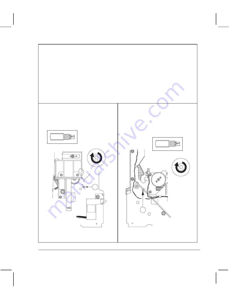
The order in which you replace the screws on the entry platen is important.

If the plotter is attached to a support, detach it.

Turn the plotter on its back.

Reconnect the media sensor to the entry platen (see also page 6Ć26).

Position the entry platen between the two sideplates.

Replace the indicated screw on the

leftĆhand side. (


dogĆpoint screw.)

Tighten this screw, making sure that the

entry platen is aligned tight against the

sideplate.

1

Torx-15

Replace the indicated screw on the

rightĆhand side. (


dogĆpoint screw.)

There must be no space between the entry

platen and the

sideplate. It doesn't

matter if there is a small space between

the entry platen and the

sideplate.

2

Torx-15


Position the top of the entry platen under all of the small pivots on the inside

of both sideplates, except the back pivot. Rest the entry platen against the back pivot.

Position the bottom of the entry platen above the bottom cover of the plotter.

6Ć67 

Removal and Replacement

C3187Ć90000


Содержание DesignJet 200

Страница 1: ... ...

Страница 2: ...The procedures described in this manual are to be performed by HPĆqualified service personnel only Serious shock hazard leading to death or injury may result if you do not take the following precautions Ensure that the ac power outlet mains has a protective earth ground terminal Disconnect the plotter from the power source prior to performing any maintenance Prevent water or other liquids from run...

Страница 3: ... ...

Страница 4: ...nnel only The HP ongoing training course CEV2ĆTIJ provides training for HP Customer Engineers on servicing the complete HP DesignJet series of largeĆformat thermalĆinkjet plotters Part numbers for plotter options accessories and service parts are located in chapter 10 The term refers generically to models C3180A and C3187A The term refers generically to models C3181A and C3188A A small arrow is us...

Страница 5: ...es 1Ć4 Media Margins 1Ć4 Other Plotter Features 1Ć4 Upgrading a DesignJet 200 1Ć4 Power Requirements 2Ć2 Choosing an Interface Cable more User s Guide 2Ć2 Choosing a Suitable Plotter Environment more User s Guide 2Ć3 Environmental Specifications 2Ć3 Plotter Dimensions and Weight 2Ć3 Unpacking and Assembling the Plotter 3Ć2 Inspecting the Plotter for Damage 3Ć3 Repacking the Plotter 3Ć3 Assembling ...

Страница 6: ...Sensing Media Presence 5Ć2 Media Sensor 5Ć2 Gripping the Media 5Ć6 Pinch Arms 5Ć6 PinchĆArm Sensor 5Ć6 Advancing the Media 5Ć7 MediaĆDrive Mechanics 5Ć7 MediaĆDrive Accuracy 5Ć7 Providing a Force on top of the Media 5Ć8 Bail 5Ć8 BailĆLift Mechanics 5Ć8 Bail Sensor 5Ć8 Stretching the Media 5Ć9 Overdrive 5Ć9 Moving the Carriage 5Ć9 CarriageĆDrive Mechanics 5Ć9 Detecting the Media Edges 5Ć10 Line Sen...

Страница 7: ...e Electronics 5Ć18 Fan 5Ć18 System Data Flow 5Ć19 Input Output 5Ć19 Parser 5Ć19 Display List 5Ć19 Converters 5Ć20 Swath Holding Area 5Ć20 Swath Manager 5Ć20 PrintĆEngine Controller 5Ć20 Swath RAM 5Ć20 CartridgeĆInterface ASIC 5Ć20 Carriage ASIC and Cartridge Drivers 5Ć20 Plotter Architecture 5Ć21 Main PCA 5Ć22 Main Processor System 5Ć23 Main Processor 5Ć23 ROM 5Ć23 Processor Support ASIC 5Ć24 Shuf...

Страница 8: ...age Processor 5Ć29 Nozzle Timing ASIC 5Ć30 Servo Processor Interface 5Ć30 A D Converter 5Ć30 Print Cartridges 5Ć30 Line Sensor 5Ć30 Front Panel PCA 5Ć31 LEDs 5Ć31 Key Pad 5Ć31 Power Supply 5Ć32 Safety Precautions 6Ć2 ESD Precautions 6Ć2 Reassembly 6Ć2 Required Tools 6Ć3 Repair Procedures 6Ć5 Removing the ElectronicsĆEnclosure Cover 6Ć5 Removing the Memory Module DRAM SIMM 6Ć7 Removing the Main PCA...

Страница 9: ... the YĆTensioner and Housing 6Ć45 Removing the Cartridge Carriage and Main Drive Belt 6Ć48 Removing the Bail Sensor 6Ć55 Removing The Bail 6Ć56 Removing the Service Station 6Ć57 Removing the Overdrive Roller 6Ć60 Removing the Overdrive Enclosure 6Ć62 ReĆinstalling the Overdrive Enclosure 6Ć63 Removing the Entry Platen 6Ć65 ReĆinstalling the Entry Platen 6Ć67 Removing the Drive Roller 6Ć69 Removing...

Страница 10: ...ibrate 8Ć11 Print Quality 8Ć11 Diagnosing Problems 8Ć11 Other Tips 8Ć11 Servo ControlĆSystem Failures 8Ć12 MediaĆAxis XĆAxis Shutdown 8Ć12 CarriageĆAxis YĆAxis Shutdown 8Ć12 Frequent Cartridge Failure 8Ć12 Remove Tape and Align Cartridges 8Ć12 Damaged Encoder Strip 8Ć12 Incompatibility between Carriage and Firmware 8Ć12 Misaligned Cartridge Caps 8Ć13 Function of the Cartridge Caps 8Ć13 What can Ca...

Страница 11: ...Test 8Ć19 Service Configuration Plot 8Ć19 Service Monitor Data Display 8Ć19 Servo Encoder Test 8Ć19 StepperĆMotor Test 8Ć20 WindowĆSensor Test 8Ć20 Which Service Test to Perform 8Ć21 Performing the Service Tests 8Ć22 Bail Cycle Test 8Ć22 BailĆSensor Test 8Ć22 Electrical Test 8Ć22 Input Output Test 8Ć23 MediaĆSensor Test 8Ć23 PinchĆArmĆSensor Test 8Ć23 Service Configuration Plot 8Ć23 Service Monito...

Страница 12: ...Support 9Ć11 Change in Trailing Cable 9Ć13 Change in Carriage 9Ć14 Change in Bail and Overdrive Parts 9Ć14 Exchange Assemblies 10Ć2 Replacement Parts 10Ć3 Part Lists and ExplodedĆView Diagrams Legs and Media Bin 10Ć4 Window Center and Bottom Covers 10Ć6 Electronics Enclosure 10Ć8 Left Endcover and Trim 10Ć10 Right Endcover and Trim 10Ć12 CarriageĆAxis Drive Left End 10Ć14 Service Station 10Ć16 Car...

Страница 13: ...l as providing protection against electrical shock in case of a fault A terminal marked with this symbol must be connected to ground in the manner described in the installation operating manual and before operating the equipment Frame or chassis terminal A connection to the frame chassis of the equipment which normally includes all exposed metal Alternating current Direct current Alternating or di...

Страница 14: ... ...

Страница 15: ... ...

Страница 16: ... Printer Job Language PJL The plotters support HPĆGL 2 with both the Japanese Kanji and the Roman character sets The plotters operate with a number of computer systems and graphic terminals using either RSĆ232ĆC or Centronics BiĆTronics interfaces More chapter 5 w Input Output Interfaces Customers can connect their plotters to a network through an optional HP JetDirect EX external network interfac...

Страница 17: ...0 dpi The plotting time for one plot on paper is as follows Plot Print Quality HP DesignJet 200 HP DesignJet 220 D A1 size plot E A0 size plot D A1 size plot E A0 size plot Draft approx 3 8 min approx 7 5 min approx 2 3 min approx 3 9 min Final approx 5 0 min approx 10 0 min approx 3 1 min approx 5 3 min Enhanced approx 6 5 min approx 10 6 min The plotter legs and media bin are optional Media type...

Страница 18: ...following maxima and minima The media margins define the real available plotting area on the media Automatic mediaĆedge sensing Automatic cartridge alignment testing and servicing BuiltĆin diagnostic and demonstration plots Users can order an upgrade kit to upgrade a DesignJet 200 to a DesignJet 220 The kit should be installed by HPĆqualified service personnel only 210 625 mm 8 3 24 6 in 210 1625 ...

Страница 19: ... ...

Страница 20: ... power cord supplied with the plotter should meet the plug requirements for the geographical area However different power cords international options are available Cable part numbers chapter 10 Choosing an Interface Cable Instructions User s Guide chapter 1 w Choosing an interface cable A short cable less than 15 meters or 50 feet is recommended for the RSĆ232ĆC interface A longer cable is permiss...

Страница 21: ...environment Plotter media Cartridges Temperature Relative Humidity 40 to 70_C 40 to 158_F 5 95 40 to 60_C 40 to 140_F Acoustics Operating Idle Sound Pressure Sound Power 54 dB Acoustic 6 5 bels A 20 dB A 3 6 bels A These specifications are typical sound pressures at a oneĆmeter bystander position Idle specification assumes fan is off Plotter Dimensions and Weight Plotter Model C3180A C3187A C3181A...

Страница 22: ...2Ć4 Site Planning and Requirements C3187Ć90000 ...

Страница 23: ... ...

Страница 24: ... for damage If the shipping container shows signs of damage retain it until you have checked the contents of the shipment and verified the performance of the plotter Unpack and assemble the plotter following the series of illustrations below The packaging is due to change in late 1994 Part number of future unpacking instructions Chapter 10 1 2 3 4 5 6 7 8 ...

Страница 25: ...er and the nearest HP Sales and Support Office Retain the shipping container and insulation material for the carrier s inspection The Sales and Support Office will arrange for the repair or replacement of the plotter You can order a repacking kit if you need to repack the plotter and don t have the shipping container and insulation material Part numbers chapter 10 9 1 2 10 11 1 2 1 2 A B 12 2 1 2 ...

Страница 26: ...d Configuration C3187Ć90000 Assembling the Legs and Media Bin Optional If the user has purchased the optional legs and media bin for the plotter assemble them following the series of illustrations below 1 2 3 45 kg 99 lb ...

Страница 27: ... 4 1 2 3 4 5 6 mm 0 25 in 5 1 2 3 4 5 B A B A A B A B X X X ...

Страница 28: ... Form Feed Print Quality Media Type Cancel Both ON Both ON Enhanced Film 3Ć6 Installation and Configuration C3187Ć90000 Installing the Plotter Instructions User s Guide chapter 1 Setting up the plotter The power cord supplied with the plotter should meet the plug requirements for the geographical area However different power cords international options are available Cable part numbers Service Manu...

Страница 29: ...re that the plotter is properly functioning and to help identify problems if any are detected Whenever you switch the plotter on it automatically performs a series of internal selfĆtests and mechanical initialization sequences If a failure occurs an error is indicated on the frontĆpanel LEDs You can perform a failure analysis by interpreting the LED error code Details chapter 8 You can check prope...

Страница 30: ...3Ć8 Installation and Configuration C3187Ć90000 The following is a scaled version of a DesignJet 200 setup sheet ...

Страница 31: ... ...

Страница 32: ...olution if necessary Do not use abrasive cleaners on the window 3 Wipe the plotter dry with a soft lintĆfree cloth Cleaning the Drive Roller Due to the ink s reflectance ink spilled on the roller can disrupt the plotter s edgeĆsensing function To remove any ink from the roller perform the following procedure 1 Connect the plotter to the ac power source 2 Switch the plotter ON and wait for it to fi...

Страница 33: ... ...

Страница 34: ...chapter 2 w Loading media Sensing Media Presence The media sensor is an optosensor and is mounted towards the right end of the entry platen Illustration page 10Ć23 Two articulated levers block the optical path between emitter and receiver when media is not loaded When media is loaded both levers are rotated thus clearing the optical path and changing the sensor state from open to closed This doubl...

Страница 35: ...ical sensor optical path closed by both flags Drive roller stopped Front panel Load Media LED on Media inserted Primary flag Secondary flag Photo sensor window Drive roller stopped Media inserted but has not yet reached the secondary flag Primary flag rotated 90 counter clockwise active Secondary flag resting on plastic detector housing idle Optical sensor optical path blocked by secondary flag Dr...

Страница 36: ...e Secondary flag rotated 35 counter clockwise active Optical sensor optical path cleared by both flags Drive roller full speed inwards engaging media Front Panel Load Media LED off Busy LED on Media Length Measurement front edge detected When the secondary flag clears the optical path the roller is activated As the secondary flag is closer to the roller paper skew is minimized allowing a deeper me...

Страница 37: ... in previous position active Optical sensor optical path blocked by falling edge of primary flag Driver roller slows down but still rotating inwards Front Panel Load Media LED off Busy LED on Media Length Measurement rear edge detected As soon as the optical sensor detects that the primary flag is back in it s original position the roller motion slows down but needs some time to overcome the syste...

Страница 38: ...ag clears the sensor The rear edge s position is located when the primary flag pushed by the rear media edge clears the optical path If you pull the media parallel to the plotter length while attempting to clear a media jam you could break the flags Gripping the Media When you load media it is gripped by the pinchĆarms Illustration page 10Ć27 The pinchĆarm sensor is an optical sensor that is attac...

Страница 39: ...print quality is maintained The mediaĆdrive accuracy endĆpoint accuracy or XĆaxis accuracy specifies how accurately a plotter can draw a line of a given length Specifications chapter 1 The configuration plot draws crossĆhairs 500mm apart that you can use to measure the plotter s accuracy Details chapter 7 w Accuracy Calibration All the above components of the media drive system contribute to the m...

Страница 40: ...ar and cam gear which are always in contact engage the driveĆroller gear on the left end of the drive roller The mediaĆdrive system drives the drive roller and also the cam and engagingĆlever gears The autoĆcam which is attached to the cam gear turns with the gear The autoĆcam contacts the left bail bracket and pushes up on the bracket As the bracket is pushed the bail lifts The bailĆsensor switch...

Страница 41: ...peedĆratio gear overdrive gear cluster and drives the overdrive roller in the forward direction only Moving the Carriage The Carriage YĆaxis drive consists of a DC motor driving the carriage by means of a dual kevlar belt system incorporating three pulleys and two tensioner assemblies Part illustrations pages 10Ć19 and 10Ć21 A gear pinion pressed onto the carriageĆmotor shaft drives a small belt t...

Страница 42: ...ia edge The media is advanced and the sensor checks for media skew crooked loading The line sensor on the cartridge carriage is also used to D Detect and measure lines drawn on media when performing cartridge alignment D Detect and measure lines drawn on media when performing accuracy calibration D Scan the setup sheet HardĆclip side margins provide protection against writing on the drive roller d...

Страница 43: ...ink from flowing out through the nozzles The print head flex circuit located on the cartridge contains the cartridge interface interconnect and nozzles Inkjet cartridges invoke a thermal dropĆonĆdemand technology A voltage is applied to a resistive area on the head superheating the bottom layer of the ink droplet and causing nucleation similar to boiling water The ink boils producing a bubble of w...

Страница 44: ...o make the electrical contact between the plotter and the cartridges The elastomer spring pads behind each flex circuit ensure the dimples contact the tab circuits with enough pressure The carriage PCA is part of the carriage assembly It connects to the main PCA through the trailing cable which passes through a split torroid to reduce radioĆfrequency interference The Carriage PCA contains D Line s...

Страница 45: ...long one of two orthogonal axes refers to the ability of the plotter to print a single dot at every location on a grid is the ability of the plotter to selectivity position dots on a grid finer than the trueĆdpi grid It is used to produce higher print quality output 600 addressable dpi Enhanced Mode 300 dpi Final Mode Both DesignJet 200 and DesignJet 220 plotters use two 300Ćdpi print cartridges H...

Страница 46: ... the 300Ćdpi grid in draft mode but to increase plotting speed Dot size is not varied in any of the print modes is fast and uses half the ink of true 300Ćdpi resolution Special algorithms control dot placement creating a virtual 300Ćdpi image rather than skipping every other dot The image appears considerably lighter than the true 300Ćdpi print quality uses true 300Ćdpi resolution Plotters set to ...

Страница 47: ...rriage Speed Swath Delay Pass Density Paper Draft 300x300 1 24ips 0 50 Final 300x300 1 16 7ips 1sec 100 Enhanced addressable 600x600 2 16 7ips 0 5sec 50 Vellum Transl Draft 300x300 1 24ips 0 50 Final 300x300 2 16 7ips 1sec 50 Enhanced addressable 600x600 4 16 7ips 0 5sec 25 Film Final 300x300 2 16 7ips 3sec 50 Enhanced addressable 600x600 4 16 7ips 1 5sec 25 A is the amount of data printed in one ...

Страница 48: ...s realignments are done by varying the firing timing of each nozzle resistor The stepper motor presses up on the lower link of the three adjustmentĆlinkage pieces by means of the plastic actuator pressed onto the motor shaft This action lowers the top link of the adjustment linkage The carriage moves and the adjustment cam which comes into contact with the top link is rotated The cam action causes...

Страница 49: ... removed this buildup can affect nozzle directionality and lead to nozzle failure Periodically during operation of the cartridge this buildup is removed by dragging a wiper across the nozzle plate Illustration page 10Ć15 The stepper motor presses down on the lower link of the wiper assembly by means of the plastic actuator pressed onto the motor s shaft As the lower link is pushed down the upper l...

Страница 50: ...hes X and Y alignment A flat feature on the sled butts against the carriage to establish the Z alignment Checking correct alignment chapter 8 w Frequent Cartridge Failure Sealing the Nozzles The cartridge cap creates a closed volume of air around the nozzles which is humidified by firing one drop per nozzle The air volume in the cap is compressed resulting in a positive pressure at the nozzles Thi...

Страница 51: ... the I O buffer The parser removes data from the I O buffer one byte at a time interprets the data and transforms it into graphic objects which are mapped onto the display list The parser can interpret either raster or vector data It adds positional information to the data indicating where it is placed on the display list It continues building the display list until the entire plot has been sent o...

Страница 52: ...o the physical swath RAM area The plotter s microprocessor has a feature called burst mode enabling data to be copied from one area of memory to another very quickly The printĆengine controller uses the variables calculated by the swath manager to determine the stop and start positions of the swath and thus control the carriage movement The swath RAM is dedicated RAM memory and not part of the DRA...

Страница 53: ...RAM I O Centronics RS 232 Shuffler ASIC Swath RAM 256 KB Support ASIC Encoders Motor Drivers Nozzle Timing ASIC Carriage Processor 8051 Servo Processor 8052 EEPROM 256 Cartridge Drivers Line Detector Sensors Front Panel Plotter Architecture The plotter electronics besides sensors and cables consist of the following assemblies Main PCA Carriage PCA FrontĆPanel PCA Power Supply These are described o...

Страница 54: ...32 Media axis encoder Front panel PCA Bail sensor Window sensor Media sensor Pinch arm sensor Media motor Carriage motor MAIN PCA Carriage PCA Stepper motor Fan Power supply SIMM socket The main PCA contains most of the plotter electronics that is D Main processor system D Servo processor subsystem D Some power components ...

Страница 55: ... ASIC Shuffler ASIC with swath memory Input output interfaces DRAM Main Processor System The main processor interprets graphicsĆlanguage commands received through the input output I O prepares a bit map of the data to be printed and issues commands to the servo processor to synchronize the carriage and roller movements for each swath printed The firmware code is contained in either two masked ROMs...

Страница 56: ...re able to operate with the plotter as they do with standard Centronics devices BiĆTronics is a signaling method for a speedĆadaptive fully interlocked bidirectional parallel communications channel between a peripheral and a host The features of BiĆTronics are Provides the capability to send data from the host computer to the plotter at a higher speed by shortening the signal timing values Provide...

Страница 57: ...ter and the baudĆrate select register using the configuration data from the EEROM Two MBytes of DRAM for system use and I O data storage reside permanently on the Main PCA In addition a 72Ćpin socket for the industryĆstandard DRAM SIMM is provided for optional memory The socket supports a DRAM SIMM of 2 MB 4 MB or 8 MB PowerĆon reset signals are used to initialize the processorĆsupport ASIC shuffl...

Страница 58: ...r Sensors 8052 Servo Processor Servo Processor System The servo processor controls all of the plotter actuators Executing the commands issued by the main processor it reads the carriage and roller position from the processor support ASIC and writes the needed control data to the PWM Pulse Width Modulation generators in that ASIC Through a serial link the servo processor sends nozzleĆtiming data to...

Страница 59: ...hether the pinchĆarms have been raised The servo processor uses the sensor to determine the pinchĆarm position during the initialization sequence D The detects whether the bail has been raised The servo processor uses the sensor to determine the bail position during the initialization sequence A serial EEROM is used as nonvolatile storage for calibration and configuration data This data is typical...

Страница 60: ...artridge resistors an active sense circuit on the carriage PCA feeds back an error signal to the main PCA On the carriage PCA the cartridge supply voltage is sensed by a precision resistor divider and compared with 2 5V reference This error is amplified buffered and transmitted to the main PCA through the trailing cable The voltage is regulated by a regulator on a heatsink The plotter electronics ...

Страница 61: ...lator for the 20ĆV supply is located on the main PCA but an active sense circuit on the carriage PCA senses the voltage at the highĆfrequency bulk charge source capacitors The carriage processor system consists of the following Carriage processor Nozzle timing ASIC Servo processor interface AnalogĆtoĆDigital A D Converter Print cartridges Line sensor The carriage processor s primary task is to con...

Страница 62: ...cessor to determine whether each print cartridge is inserted properly A thermistor mounted on the carriage PCA allows the carriage processor to sense ambient temperature The processor can adjust the amount of energy delivered to a print cartridge by changing the nozzle firing time though the nozzle timing ASIC The plotters compensate for changes in ambient temperature and self heating of the print...

Страница 63: ...The LED layout is shown below led 1 led 4 led 7 led 2 led 5 led 8 led 3 led 6 led 9 Front Panel LEDs The keypad layout is shown below led 2 led 3 led 6 led 7 key 0 key 1 Switch 1 Switch 2 Switch 3 Switch 4 Switch 5 Switch 6 Switch 7 Switch 8 Front Panel Key Pad The switches are connected as a 4x2 matrix The switch matrix when scanned is driven by the four LED control signals led 2 led 3 led 6 and ...

Страница 64: ...Fan power and RS 232 driver 12 V RS 232 driver 5 V IC power and sensors The primary portion of the supply contains fusing and input protection circuitry line filters and a rectifier The primary output is converted to a pulseĆwidthĆmodulated PWM unidirectional current by a flyback dcĆtoĆdc converter The secondary portion of the power supply contains the four secondary windings of the transformer th...

Страница 65: ... ...

Страница 66: ...remove an IC or a printed circuit assembly PCA from its conductive foam pad or conductive packaging until you are ready to install it Ground your body while disassembling and working on the plotter After removing a cover from the plotter attach a clip lead between the PCA common and earth ground Touch all tools to earth ground to remove static charges before using them on the plotter After removin...

Страница 67: ...equired Tools The following are the tools required to disassemble and repair the plotters D Long Torx screwdriver with the indicated attachments T8 T9 T10 T20 T15 T25 D 90d TorxĆ15 key D Pozidriv PZ1 screwdriver D Small flatĆblade screwdriver ...

Страница 68: ...oval and Replacement C3187Ć90000 D Nut driver with indicated attachments 3 16 inch 5 5 mm and D NeedleĆnose pliers D Cutting pliers D Spring hook D Loopback connector HP Part Number 07440Ć60302 D 10X Magnifier ...

Страница 69: ... that the two small wire clamps of the parallel port are positioned vertically Power inlet cord not connected Remove the screws that attach the electronicsĆenclosure cover to the electronics enclosure Gently lift open the electronicsĆenclosure cover to an angle of 45d Torx 20 or Flat 6Ć5 Removal and Replacement C3187Ć90000 Repair Procedures ...

Страница 70: ... Push the cover up so that its tabs can slide out of the slots at the top of the electronics enclosure Carefully pull the cover clear of the plotter Tab 6Ć6 Removal and Replacement C3187Ć90000 ...

Страница 71: ... springs apart at the ends of the slot tilt the outer edge of the DRAM SIMM downwards Once the DRAM SIMM is released from the springs gently pull it clear of the slot Slot for DRAM SIMM 6Ć7 Removal and Replacement C3187Ć90000 The user may have installed an optional DRAM SIMM in the plotter Perform the following procedure if you need to remove it ...

Страница 72: ...you and the notch to your left Tilt the nonĆmetallic edge downwards and firmly push the module into the slot Gradually tilt the module upwards and push it in until it clicks into place 6Ć8 Removal and Replacement C3187Ć90000 To reinstall the SIMM perform the following procedure ...

Страница 73: ... Remove the two screws from the serial RSĆ232ĆC connector Remove the two screws from the parallel connector D A1Ćsize plotters only Open the flexible DANGER HIGH VOLTAGE insulation cover Pozidriv PZ1 3 16 inch 6Ć9 Removal and Replacement C3187Ć90000 ...

Страница 74: ...AIN PCA Carriage PCA Stepper motor Fan Power supply Disconnect all 12 cable connectors from the main PCA C A U T I O N Make sure to connect all cables in the correct orientation and to the correct sockets Remove the five screws that secure the main PCA to the electronics enclosure Temporarily leave the screws loose tighten the serial and parallel connector screws first then tighten the PCA screws ...

Страница 75: ...s installed on the original PCA remove it and install it on the new PCA EPROMs Masked ROMs Empty Empty After having installed a new main PCA perform the following calibrations in the given order Details chapter 7 1 Bail calibration 2 MediaĆsensor calibration 3 Cartridge alignment 4 Accuracy calibration 5 SetupĆsheet calibration Empty pair of holes U28 U9 U29 U4 U28 U9 U29 U4 Part numbers chapter 1...

Страница 76: ...owerĆdistribution connector from the powerĆsupply PCA Remove the electronicsĆenclosure cover page 6Ć5 Open the flexible DANGER HIGH VOLTAGE insulation cover dc power distribution connector ac connector 6Ć12 Removal and Replacement C3187Ć90000 ...

Страница 77: ... Remove the six screws that secure the powerĆsupply PCA to the electronics enclosure Lift the powerĆsupply PCA clear of the plotter Torx 10 6Ć13 Removal and Replacement C3187Ć90000 ...

Страница 78: ... cover page 6Ć5 Fan connector Open the flexible DANGER HIGH VOLTAGE insulation cover Disconnect the fan connector from the main PCA and holding clip Remove the two screws that secure the fan to the electronics enclosure Torx 20 6Ć14 Removal and Replacement C3187Ć90000 ...

Страница 79: ...the right endcover and the window apart far enough to lift the window up so that the right pivot just clears its socket Move the window to the right so that the left pivot slides out of its socket and lift the window clear of the plotter Torx 15 6Ć15 Removal and Replacement C3187Ć90000 ...

Страница 80: ... page 6Ć15 Loosen the two latch screws on the underside of the center cover Slide the two latches horizontally towards the center of the plotter clear of the two endcovers Torx 15 6Ć16 Removal and Replacement C3187Ć90000 ...

Страница 81: ...Torx 15 Remove the screws from the back of the center cover Slide the center cover vertically upwards and lift it clear of the plotter 6Ć17 Removal and Replacement C3187Ć90000 ...

Страница 82: ...hten the screws Remove the three screws from the left side of the left endcover Remove the window page 6Ć15 and the center cover page 6Ć16 Remove the two screws on the left front trim and the two screws on the left back trim C A U T I O N Torx 15 Torx 15 If the plotter is mounted on legs the two leftĆhand screws that attach the plotter to the legs Maintaining an even pressure on the top and bottom...

Страница 83: ...e right side of the right endcover Remove the window page 6Ć15 and the center cover page 6Ć16 Remove the two screws on the right front trim and the two screws on the right back trim C A U T I O N Torx 15 Torx 15 If the plotter is attached to a plotter stand the two rightĆhand screws that attach the plotter to the stand Maintaining an even pressure on the top and bottom of the endcover pull it to t...

Страница 84: ...nsioner bracket Reassembling Remove the two shoulder screws that attach the automatic cartridgeĆadjust linkage to the left sideplate and lift the linkage clear of the plotter C A U T I O N Do not crossĆthread or overĆtighten the screws Reassembling Stepper motor shaft Bottom arm of linkage Torx 15 6Ć20 Removal and Replacement C3187Ć90000 ...

Страница 85: ...r page 6Ć18 Open the flexible DANGER HIGH VOLTAGE insulation cover Disconnect the stepperĆmotor cable connector from the main PCA and the holding clip Stepper motor connector Remove the bottom shoulder screw on the cartridgeĆadjust linkage and lower the lever arm below the stepper motor Torx 15 6Ć21 Removal and Replacement C3187Ć90000 ...

Страница 86: ... not crossĆthread or overĆtighten the screws Move the stepper motor toward the rear of the plotter Pull the stepperĆmotor cable gently out from the electronics enclosure through the hole in the left side of the electronics enclosure and lift it and the stepper motor clear of the plotter Torx 10 6Ć22 Removal and Replacement C3187Ć90000 ...

Страница 87: ...sensor cable connector from the main PCA and from the ferrite on the right sideplate Pinch arm sensor connector Remove the two screws that attach the pinchĆarm sensor to the right sideplate Lift the pinchĆarm sensor with cable clear of the plotter Torx 10 Pinch arm sensor KEEP THIS AREA FREE OF CABLES ÉÉÉÉ ÉÉÉÉ Reassembling Ferrite 6Ć23 Removal and Replacement C3187Ć90000 ...

Страница 88: ...ht endcover page 6Ć19 Disconnect the windowĆsensor cable connector from the main PCA Window sensor connector Clip Clip Ferrite Carefully feed the windowĆsensor cable out from the electronics enclosure and from under the motor assemblies unclipping it from the holding clips and ferrite 6Ć24 Removal and Replacement C3187Ć90000 ...

Страница 89: ...nt trim Fastener Remove the screw that attaches the window sensor to the right front trim Lift the sensor with cable clear of the plotter Sensor C A U T I O N Do not crossĆthread or overĆtighten the screw Torque 3 lb in 0 35 Nm Torx 8 6Ć25 Removal and Replacement C3187Ć90000 ...

Страница 90: ...he right endcover page 6Ć19 Disconnect the mediaĆsensor cable connector from the main PCA and from the holding clip and ferrite on the right sideplate Torx 15 Place the plotter on a flat surface and turn it on its back It requires two people to lift the plotter The ferrite holder opens from the top Reassembling The cable goes through the same ferrite as for the window sensor page 6Ć24 6Ć26 Removal...

Страница 91: ...llowing procedure Pull the media sensor straight out towards you freeing it from the underside of the entry platen Cut the plastic tie that fastens the mediaĆsensor cable to the underside of the entry platen Lift the media sensor and cable clear of the plotter Take care not to cut the mediaĆsensor cable itself C A U T I O N Calibration After having reassembled the plotter perform the mediaĆsensor ...

Страница 92: ...n the indicated position Let the tĆshaped flag rotate to its correct position Insert the bellĆshaped flag in the indicated position Let the bellĆshaped flag rotate to its correct position 6Ć28 Removal and Replacement C3187Ć90000 ...

Страница 93: ...om the main PCA Remove the two screws that attach the toroid to the rear of the electronics enclosure Flex the cover to open it Do not detach the cover from the plotter Trailing cable connector Pull off the two endcaps of the toroid and remove the toroid from the trailing cable Torx 10 If you are installing a new trailing cable make sure the main PCA is compatible with it Details chapter 9 6Ć29 Re...

Страница 94: ...et Free the cable from the rear tray and bracket pulling it up through the slot at the top of the electronics enclosure assembly Rear tray Plastic ties Bracket Trailing cable connector Cartridge carriage PCA Use the old trailing cable as a template to bend and crease the new trailing cable to exactly match the creases in the old trailing cable 6Ć30 Removal and Replacement C3187Ć90000 ...

Страница 95: ... enclosure Carefully remove the rightĆhand cartridge spring from the cartridge carriage Remove the trailingĆcableĆbracket screw from the cartridge carriage Pull the trailing cable up through the slot at the top of the electronics enclosure assembly and lift it with rear tray and bracket from the plotter Rear tray Rear tray Bracket Torx 20 Torx 10 6Ć31 Removal and Replacement C3187Ć90000 ...

Страница 96: ...rect positioning of the frontĆpanel cable for reassembling Incorrect positioning could cause obstruction of the cartridge carriage or motor gears Unclip the windowĆsensor cable and frontĆpanel cable from their holding clip on the underside of the frontĆpanel assembly Release the frontĆpanel cable from its clamp on the main PCA and from its holding clip on the right side of the plotter C A U T I O ...

Страница 97: ... flat ferrite on the right sideplate and out from under the motor assemblies Remove the two screws and washers that attach the frontĆpanel assembly to the right sideĆplate and lift the frontĆpanel assembly with cable clear of the plotter Torx 20 6Ć33 Removal and Replacement C3187Ć90000 ...

Страница 98: ...emove the center cover page 6Ć16 Remove the right endcover page 6Ć19 Remove the frontĆpanel assembly page 6Ć32 On the underside of the frontĆpanel assembly press the four transparent plastic tabs inwards and remove the PCA and LED assembly 6Ć34 Removal and Replacement C3187Ć90000 ...

Страница 99: ...Disconnect the carriageĆmotor cable from the main PCA connector labelled Y and from the lowest ferrite holder on the rightĆhand side of the plotter Pressing the small drive belt against the tensioner wheel in the belt tensioner to loosen the belt slide the belt off of the motor gear then carefully release your hand from the the tensioner wheel Loosen the two carriageĆmotor screws about 1 2 cm abou...

Страница 100: ...Rotate Pull Rotate the motor in the indicated direction Pull the motor down clear of its bracket 6Ć36 Removal and Replacement C3187Ć90000 ...

Страница 101: ...the carriage motor page 6Ć35 Disconnect the mediaĆmotor cable from the main PCA connector labeled X and from the uppermost ferrite holder on the rightĆhand side of the plotter Paper motor connector Remove the two screws that secure the driveĆroller gear to the driveĆroller shaft Torx 10 Reassembling Remove the driveĆroller gear from the driveĆroller shaft 6Ć37 Removal and Replacement C3187Ć90000 ...

Страница 102: ...ter Torx 15 Calibration After having reassembled the plotter perform the accuracy calibration Details chapter 7 Reassembling The worm pinion and driveĆroller gear mesh slightly during use Don t install a new motor and an old gear or vice versa install the gear that comes with the motor Apply the grease that comes with the new motor to the worm pinion and driveĆroller gear 6Ć38 Removal and Replacem...

Страница 103: ... strip is fragile Do not damage it Lay it on a flat surface when it is not in the plotter Remove the nut and washer that secure the encoder strip to the encoder springĆbracket on the right side of the plotter 5 5 mm Remove the nut and washer that secure the encoder strip to the service station on the left side of the plotter 5 5 mm 6Ć39 Removal and Replacement C3187Ć90000 ...

Страница 104: ...carefully release the encoder strip from the service station Compress Release 1 2 Service station Encoder strip Spring bracket Carefully pull the encoder strip through and out of the carriage assembly Lay the encoder strip on a flat surface 6Ć40 Removal and Replacement C3187Ć90000 ...

Страница 105: ...pertures in the cartridgeĆcarriage assembly With washer and nut secure the encoder strip to the service station Press the forward end of the encoder springĆbracket slightly inward and place the encoder strip between the tabs and over the threaded post on the encoder springĆbracket 5 5 mm Compress Spring bracket Threaded post Tabs 6Ć41 Removal and Replacement C3187Ć90000 ...

Страница 106: ...ith washer and nut secure the encoder strip to the encoder springĆbracket Slide the carriage back and forth the length of its travel to ensure free movement 5 5 mm 6Ć42 Removal and Replacement C3187Ć90000 ...

Страница 107: ...nsioner housing Trailing cable guide Torx 15 C A U T I O N Exercise care to avoid damaging the ferrite ring when carrying out the following instructions Cut the plastic tie on the spring in the ferrite ring located where the trailingĆ cable guide attaches to the YĆdrive bracket Ferrite ring Spring and tie Trailing cable guide Using a screwdriver compress and release the spring from between the ins...

Страница 108: ...the rear of the plotter rotate it to clear the arm of the cartridgeĆadjustment cam on the cartridge carriage and lift the trailingĆcable guide clear of the plotter C A U T I O N Be careful not to scrape the cartridgeĆcarriage PCA with the trailingĆcable guide if you are sliding the guide under the trailing cable 6Ć44 Removal and Replacement C3187Ć90000 ...

Страница 109: ...he window page 6Ć15 Remove the center cover page 6Ć16 Remove the left endcover page 6Ć18 Slide the cartridge carriage towards the center of the plotter in order to access the tensioner Remove the screw that attaches the trailingĆcable guide to the tensioner housing Remove the tensionerĆplate screw Tensioner housing Trailing cable guide Torx 15 Torx 15 C A U T I O N 6Ć45 Removal and Replacement C31...

Страница 110: ...e right end of the tensioner plate up and clear of the retaining tab Tensioner plate Tab Decompress the tensioner spring by allowing the tensioner plate to move toward the rear of the plotter Tensioner plate Tensioner spring Remove the YĆtensioner spring and YĆtensioner from the housing 6Ć46 Removal and Replacement C3187Ć90000 ...

Страница 111: ...lide the YĆtensioner housing out from the YĆtensioner bracket Y tensioner bracket Y tensioner housing Release the main idler from the cartridgeĆcarriage belt Lift the YĆtensioner housing clear of the plotter 6Ć47 Removal and Replacement C3187Ć90000 ...

Страница 112: ...Ćstrip bracket to the serviceĆ station housing Encoder strip bracket Service station housing Torx 15 Lift the encoderĆstrip bracket clear of the plotter Remove the three screws that secure the serviceĆstation cover to the serviceĆstation housing Torx 15 Cover If you are installing a new cartridge carriage or a new carriage PCA ensure that the plotter firmware is compatible with it Incompatibilitie...

Страница 113: ...position with one hand tilt the forward edge of the serviceĆstation cover up and lift the cover clear of the serviceĆstation housing Sled Cover 1 2 Lift the serviceĆstation sled up slightly and release the sled spring from the serviceĆstation housing 6Ć49 Removal and Replacement C3187Ć90000 ...

Страница 114: ...e plotter Pressing the small drive belt against the tensioner wheel to loosen the belt slide the belt off of the motor gear then carefully release your hand from the the tensioner wheel Small drive belt Remove the screw and washer that attach the encoderĆstrip spring to the spring bracket Encoder strip spring Torx 15 6Ć50 Removal and Replacement C3187Ć90000 ...

Страница 115: ...ing this keep the palm of one hand beneath the double pulley to catch the doubleĆpulley bushing Bracket Double pulley Bushing Washer Disconnect the trailingĆcable connector from the cartridgeĆcarriage PCA Trailing cable connector Cartridge carriage PCA 6Ć51 Removal and Replacement C3187Ć90000 ...

Страница 116: ...at attaches the trailingĆcable bracket to the carriage assembly Torx 10 Lift the trailingĆcable and bracket clear of the carriage assembly Bracket Trailing cable Slide the cartridge carriage to the left side of the plotter Cartridge carriage 6Ć52 Removal and Replacement C3187Ć90000 ...

Страница 117: ...arriage rear preload bushing rides on the rear slider rod and move the carriage to the left and free of the slider rods Cartridge carriage Rear preload bushing Slider rods Separate the rear bushing and preload spring from the carriage assembly and carefully remove the carriage assembly and main drive belt from the plotter Main drive belt Cartridge carriage Preload spring Rear bushing 6Ć53 Removal ...

Страница 118: ...t clamp Remove the main drive belt from the carriage assembly Main drive belt C A U T I O N Be careful not to damage the clamps Calibration After having reassembled the plotter perform the cartridgeĆalignment routine chapter 7 Reassembling Correctly install the clamps so that they don t fall out during plotter operation 6Ć54 Removal and Replacement C3187Ć90000 ...

Страница 119: ...ctor from the main PCA and from its ferrite and holding clip on the right sideplate Carefully feed the bailĆsensor cable out from the electronics enclosure and from under the motor assemblies Unclip the bail sensor from its holder and lift it with cable clear of the plotter Calibration After having reassembled the plotter perform the bail calibration chapter 7 The ferrite holder opens from the top...

Страница 120: ... the extreme left Cartridge carriage Push both of the plastic ends of the bail towards each other to release them from the holes in the sideplates and lift the bail up and clear of the plotter 1 1 2 Push Push 6Ć56 Removal and Replacement C3187Ć90000 ...

Страница 121: ...t and washer that attach the encoder strip to the encoderĆstrip bracket 5 5 mm Loosen the two screws that attach the encoderĆstrip bracket to the serviceĆstation assembly until tension can be relieved on the encoder strip and it can be detached from the bracket 1 1 2 Bracket Encoder strip Remove the encoderĆstrip bracket from the service station 6Ć57 Removal and Replacement C3187Ć90000 ...

Страница 122: ...out 1 cm or about 1 2 inch to the left of its normal position with one hand tilt the forward edge of the serviceĆstation cover up and lift the cover clear of the serviceĆstation housing Sled Cover 2 1 Lift the serviceĆstation sled slightly up and release the sled spring from the serviceĆstation housing 6Ć58 Removal and Replacement C3187Ć90000 ...

Страница 123: ...g the wiper up Wiper Remove the screw and washer that secure the wiper rod and rocker to the left sideplate and lift the rod and rocker clear of the plotter wiper rod wiper rocker Torx 15 Remove the three screws that attach the serviceĆstation housing to the left sideplate Torx 20 Lift the serviceĆstation housing slightly up and pull it clear of the left sideplate 6Ć59 Removal and Replacement C318...

Страница 124: ...ervice station The service station is not shown in the diagram Note the position and orientation of the overdrive clutch When correctly installed the overdrive roller can be manually rotated forward only While flexing the media separator upwards slide the overdrive roller horizontally to the right until the overdrive clutch and sideplate bushing can drop free of the roller 1 3 Media separator Over...

Страница 125: ...ared the left sideplate but not entered the hole in the right sideplate Release the overdrive roller from the overdrive bushing small black clips underneath the media separator and lift the overdrive roller clear of the plotter 6Ć61 Removal and Replacement C3187Ć90000 ...

Страница 126: ...Remove the overdrive roller page 6Ć60 Remove the three indicated screws from the left sideplate 1 2 3 Torx 15 Torx 20 LEFTĆHAND SIDE Remove the two indicated screws from the right sideplate 1 2 Torx 15 Torx 20 RIGHTĆHAND SIDE Lift the overdrive enclosure clear of the plotter Overdrive enclosure 6Ć62 Removal and Replacement C3187Ć90000 ...

Страница 127: ...between the two sideplates Replace the two indicated screws dogĆpoint screws 1 2 Torx 15 Take care not to damage the mediaĆsensor flags The overdrive enclosure should not touch them C A U T I O N 6Ć63 Removal and Replacement C3187Ć90000 ...

Страница 128: ...4 Torx 20 Replace the indicated screw and tighten it thus aligning the overdrive enclosure with the left sideplate LEAVE LOOSE LEFTĆHAND SIDE RIGHTĆHAND SIDE 5 Tighten the two screws you inserted in step 3 Torx 15 LEFTĆHAND SIDE Torx 15 6Ć64 Removal and Replacement C3187Ć90000 ...

Страница 129: ...ar of the entry platen taking care not to damage the window sensor Remove the overdrive enclosure page 6Ć62 Remove the three indicated screws from the left sideplate 1 2 3 Torx 15 Torx 20 1 2 Torx 15 Remove the two indicated screws from the right sideplate Underneath the plotter remove the screws from the of the bottom cover Unscrew the power switch from the left sideplate Torx 20 Torx 20 Torx 20 ...

Страница 130: ...e underside of the entry platen by pulling the holder straight out Cut the plastic tie that fastens the mediaĆsensor cable to the underside of the entry platen Lift the entry platen clear of the plotter Plastic tie Take care not to cut the mediaĆsensor cable itself C A U T I O N 6Ć66 Removal and Replacement C3187Ć90000 ...

Страница 131: ...e entry platen is aligned tight against the sideplate 1 Torx 15 Replace the indicated screw on the rightĆhand side dogĆpoint screw There must be no space between the entry platen and the sideplate It doesn t matter if there is a small space between the entry platen and the sideplate 2 Torx 15 Position the top of the entry platen under all of the small pivots on the inside of both sideplates except...

Страница 132: ... plotters have four screws E A0Ćsize plotters have five screws Before reĆinstalling the overdrive enclosure ensure that both flags on the media sensor move freely when you pass a sheet of media over them Turn the plotter to its correct position After having reassembled the plotter perform the mediaĆsensor calibration 6Ć68 Removal and Replacement C3187Ć90000 ...

Страница 133: ...e following step take care not to damage the bail sensor C A U T I O N Remove the three screws that attach the mediaĆmotor mount to the right sideplate Press down on the media mount as you replace the three screws This is to ensure correct spacing between the drive roller and the cartridge nozzles Details chapter 9 Torx 20 Unclip the cables from the holding clip underneath the mediaĆmotor mount Li...

Страница 134: ...ing assembly at the right end of the drive roller is seated in the right sideplate and completely on the right side of the axial bias plate Calibration Perform the accuracy calibration after installing the drive roller Details chapter 7 6Ć70 Removal and Replacement C3187Ć90000 ...

Страница 135: ...gagingĆlever spring Reinstalling Connect the spring to the upper rung on the leg of the YĆtensioner bracket Connecting to one of the lower rungs overtightens the spring and can cause failure of the bailĆlift mechanism Remove the two screws from the camĆgear support Torx 15 Reinstalling a Remove the screw from the front leg of the YĆtensioner bracket Torx 20 b Reinstall the two screws on the camĆge...

Страница 136: ...lever located on the right side of the entry platen into the vertical position Remove the screws on the entry platen page 6Ć65 and pull it slightly forward On the right side of the plotter disconnect the rockerĆplate tension spring to relieve any remaining tension on the pinchĆarm lift mechanism ...

Страница 137: ...owards the center of the plotter Torx 8 Repeat the previous step and try to pull the cam journal and rear wire link to the right and clear of the bar cam Do not overtighten the camĆjournal screw Doing so could break the journal cause the bar cam to enter the sideplate hole and thus restrict the action of the pinchĆarm lever C A U T I O N ...

Страница 138: ...begin to slide out of the left sideplate Cam journal Bar cam Left sideplate While pressing the rightĆmost pinchĆarm assembly towards the rear of the plotter against its spring tension slide the bar cam left until it clears that pinchĆarm assembly Remove the pinchĆarm assembly and spring from the chassis Pinch arm Spring Bushing PinchĆarm assembly Repeat the previous two steps until all of the pinc...

Страница 139: ... ...

Страница 140: ...Bail failures occur during media loading Bail Calibration Bail sensor is removed or replaced Bail Calibration Bail lift mechanism is removed or replaced Bail Calibration Media sensor is removed or replaced Media Sensor Calibration Leading and trailing margins of a plot are greater than 17 mm 0 67 in Media Sensor Calibration Problems occur scanning a setup sheet Setup Sheet Calibration EEROM is cle...

Страница 141: ... Read Input Output Test Stepper Motor Test Bail Sensor Test Bail Cycle Test Bail Calibration Servo Encoder Test Setup Sheet Calibration Media Sensor Calibration Service Monitor with Shift Alt To check whether a DesignJet 220 plotter is in service mode press the ALT and SHIFT keys together and then release them If the plotter is in service mode four LEDs Draft Final Paper and Transl Vellum flash Pr...

Страница 142: ...idge carriage used to find the left and right media edges during media loading This calibration is independent of the setupĆsheet calibration The setupĆsheet calibration calibrates the same LED but the values stored are used only for scanning a setup sheet and are separate from the values strored during the cartridge alignment Aligning Cartridges With the plotter ensure the mediaĆjam lever pinchĆa...

Страница 143: ...ations C3187Ć90000 Left cartridge Right cartridge Gap If any of the leftĆcartridge or rightĆcartridge lines includes gaps then the corresponding print cartridge should be either cleaned or replaced as appropriate ...

Страница 144: ...lotters is 0 38 mm 0 015 in or 0 2 of the specified vector length whichever is greater at 23dC 73dF at 50Ć60 relative humidity on HP special polyester film Use the following formula to calculate the plotter s accuracy Measured length Desired length Desired length x 100 Error What can Affect the EndĆPoint Accuracy Various part tolerances inside the plotter affect the accuracy in particular the driv...

Страница 145: ...al conditions Use a sheet approximately 61 x 91 cm 24 x 36 in 5 Select the appropriate Media Type on the front panel 6 Load the media in portrait orientation into the plotter If using inkjet polyester film load the film with the matte dull side down 7 When the Ready LED lights up hold down the SHIFT key and press Accuracy Calib Print The LED lights up and the plotter plots a calibration plot The p...

Страница 146: ...ibration In this procedure the up position of the bail assembly is calibrated A value is stored in the EEROM when the procedure is completed Perform the bail calibration whenever the D EEROM is cleared D Main PCA is replaced D Bail falls during media loading D Bail switch is replaced D BailĆlift mechanism is removed or replaced To calibrate the bail perform the following procedure Enter service mo...

Страница 147: ...s cleared D The main PCA is replaced D The media sensor is removed or replaced D The leading and trailing margins of a plot are greater than 17 mm 0 67 in To calibrate the media sensor perform the following procedure Enter service mode D page 7Ć2 Hold down the ALT key and press Media Calibration Any loaded media is ejected by the plotter When the Load Media LED begins to flash load a sheet of medi...

Страница 148: ...eplaced D Problems frequently occur with setupĆsheet scanning To calibrate the LED perform the following procedure Enter service mode D page 7Ć2 Load a blank sheet of paper Hold down the ALT key and press Setup Sheet Calibration To verify that the calibration has been performed correctly plot a service configuration plot D page 8Ć23 and look at the field entitled Setup Sheet LED Calibration formul...

Страница 149: ...8Ć0 8 Troubleshooting ...

Страница 150: ... this chapter PowerĆOn Self Test The powerĆon self test does the following 1 Initializes the servo processor 2 Initializes the main processor 3 Tests communication between the main processor and the servo processor 4 Tests the ROM checksum 5 Causes the main processor to initialize certain firmware modules and communicate with the carriage processor 6 Tests the EEROM checksum 7 Tests the servoĆproc...

Страница 151: ...hese circuits control the media and carriage motors Tests the swath RAM A Tests the communication link between the cartridgeĆinterface ASIC and the carriage ASIC 4 Tests the available DRAM not being used by the system The length of this test is dependent on how much DRAM is installed 5 Begins mechanical initialization of the plotter Mechanical Initialization The automatic mechanical initialization...

Страница 152: ...n access it the Cartridges LED lights up indicating that you have to load reseat or replace the cartridges Instructions User s Guide 8 The cartridges are cleaned in the service station on the leftĆhand side of the plotter During the cleaning process the carriage moves slightly a number of times for the wiper to wipe the nozzles 9 The carriage then parks in the service station on the leftĆhand side...

Страница 153: ...routine 1 Remove the cartridges 2 Ensure that the protective tape has been removed and that the contacts are clean 3 Replace the cartridges 4 If the LEDs do not stop flashing when you lower the window replace both cartridges with new ones See also D later in chapter w An error was detected while scanning a setup sheet 1 Check the quality of the media and print of the setup sheet 2 If the quality a...

Страница 154: ...ter is ignoring the plotter s handshake signals If the computer is using hardware handshake ensure that the serialĆinterface cable has a handshake wire Error and Load Media flashing Possible Causes Corrective Action The media does not advance around the roller when loaded Remove the media and reload it You loaded the media too far from the right side Remove the media and reload it aligning the rig...

Страница 155: ...nd steady Error Number and Description Corrective Options 336 RSĆ232ĆC data overflow Data byte was not read before another was entered into the UART At the time of printing of this manual this error should be solved by replacing the main PCA If the problem remains consult recent service notes for a possible solution If no service note deals with this error report the problem to the HP Response Cen...

Страница 156: ...ll test Replace main PCA 49 Failure of Swath RAM test Replace main PCA 113 Failure of EEROM test Replace main PCA 53 DRAM SIMM failure Replace DRAM SIMM If problem remains replace main PCA 117 Sensor structure firmware failure At the time of printing of this manual this error should not occur If it does occur consult recent service notes for a possible solution If no service note deals with this e...

Страница 157: ...18 Bail sensor indicates the bail is up when it should be down or vice versa or the bail drops suddenly missing the notch on the auto cam See D later in this chapter w Use the bailĆsensor test to help troubleshoot Check for mechanical problems Perform the bail calibration 146 AccuracyĆcalibration error Did you load the media in the correct orientation Ensure that the marks are visible on the plot ...

Страница 158: ...n PCA 120 ServoĆprocessor communication error Replace main PCA 60 Failed communications between the carriage and main processors Check trailing cable connections and continuity If needed replace trailing cable main PCA or carriage assembly 124 The optical sensor on the carriage has failed to locate lines drawn during the cartridge calibration routine Reduce ambient light If media is not clean and ...

Страница 159: ...onstration plot is given in the User s Guide Diagnosing Problems You can use the service configuration plot to help diagnose problems The procedure for plotting the configuration plot is given on page 8Ć23 Other Tips On the following pages are tips about solving the following problems D Servo controlĆsystem failures D Frequent cartridge failure D BailĆliftĆmechanism failure D Cartridge carriage ru...

Страница 160: ...y move the carriage along the carriageĆaxis Check for any areas where the carriage may be binding D Ensure that the double pulley small drive belt small belt tensioner main belt main idler and carriage bushings are in correct working order D Perform the servo encoder service test to check for problems with the servoĆfeedback and motor drive systems Frequent Cartridge Failure Remove Tape and Align ...

Страница 161: ...ap Misalignment The most common cause is that the cap is not seated properly on the serviceĆstation sled Any of the serviceĆstation parts could cause misalignment if defective or installed incorrectly Checking CartridgeĆCap Alignment The following tools are recommended for this procedure D Soft lintĆfree wipes D NonĆpermanent ink marker dry erase type works best D 10X magnifier D Print cartridges ...

Страница 162: ...he engaging lever This can happen due to excessive part tolerances or wear D The engaging lever spring is installed on the lower rung of the YĆdrive bracket creating too much spring tension Excessive spring tension accentuates any looseness in the bail lift parts Install the spring on the upper rung D The carriage does not properly locate the engagement lever preventing the gears from engaging Any...

Страница 163: ...er Loosen the top and bottom screws of the adjustable encoderĆspring bracket Manually move the bottom of the bracket about the bracket s top screw until the encoder strip is centered in the carriage then tighten the screws Premature Wearing of Drive Belts The main belt or the small YĆdrive belt may wear prematurely if the plotter is placed near a diazo copier that uses ammonia to produce blueĆline...

Страница 164: ...lotted at all In this case you need to choose an HPĆGL Timeout period Instructions D User s Guide The timeout tells the plotter how long to wait before assuming a plot is complete Short timeout period A timeout setting that is too short results in incomplete plots Long timeout period If the plotter has finished receiving the plot data Busy LED stops flashing and remains on and is waiting for the t...

Страница 165: ...mware Details D chapter 9 w Translucent Media doesn t Load Some DesignJet 200 carriage PCAs have problems sensing translucent media The solution is to install a new cartridge carriage Further Information D chapter 9 w Binding or Missing Sensor Flags MediaĆload failures can also occur due to binding in the mediaĆaxis mechanics or missing mediaĆsensor flags Clear any binding in the mediaĆaxis mechan...

Страница 166: ...restored D Cartridge interface ASIC test Verifies the functionality of the cartridge interface ASIC D Cartridge ASIC carriage ASIC link test D EEROM checksum D On board SIMM RAM test D ROM CRC test Performs a ROM checksum and compares it to a checksum value previously stored D Swath RAM test Tests the RAM used by the cartridge interface ASIC to store the swath Input Output Test The input output te...

Страница 167: ...mportant EEROM parameters including a mileage monitor and information on the last system error D Designation of front panel keys for service tests Service Monitor Data Display Use the service monitor to compare the code sent by the computer with that received by the plotter Instead of plotting the drawing that you send the plotter prints part of the code that would otherwise have been used to plot...

Страница 168: ...er motor test continuously cycles the stepper motor thus raising and lowering the wiper and the lever mechanism It tests the following D Stepper motor D Main PCA D Cartridge adjust linkage D Wiper linkage Window Sensor Test This tests the following D Window sensor D Window sensor cable D ...

Страница 169: ...ive roller Servo encoder test EEROM Electrical test Main belt Servo encoder test Main idler Servo encoder test Main PCA Electrical test Input output test Stepper motor test Servo encoder test Bail sensor test Media sensor test Window sensor test Pinch arm sensor test Bail cycle test Mechanical interference Bail sensor test Media axis encoder motor Servo encoder test Media axis encoder cable Servo ...

Страница 170: ...ycle Test Enter service mode see page 7Ć2 Hold down the ALT key and press Bail Cycle Test Busy A Press the ALT Cancel key when you want to stop the test BailĆSensor Test Enter service mode see page 7Ć2 Hold down the ALT key and press Bail Sensor Test Busy A Open the window within 120 seconds Busy 4 Manually raise the bail Ready 5 Press the ALT Cancel key when you want to stop the test and lower th...

Страница 171: ...aĆjam lever pinchĆarm lever forward This raises the pinch arms The Ready LED should flash 2 Push the mediaĆjam lever back to its original vertical position This lowers the pinch arms The Ready LED should stop flashing and the Load Media LED should light up again Service Configuration Plot 1 Enter service mode see page 7Ć2 2 Set the Plot Quality to Final on the front panel 3 Load a sheet of A1Ćsize...

Страница 172: ...ain PJL universal exit language 6 Compare the code printed with the code sent from the computer to check if communication between the computer and the plotter is functioning correctly Servo Encoder Test 1 Enter service mode see page 7Ć2 2 Hold down the ALT key and press Servo Encoder Test The LED lights up and the carriage moves to the center of the plotter Both the carriage and the roller then mo...

Страница 173: ...ts are not being fired straight are due to nozzle imperfections and cannot be fixed Others may be caused by nozzle contamination You can sometimes correct these by cleaning the nozzles D User s Guide Use the fifth and sixth bars to detect D Banding D Problems with nozzle firing direction D Misalignment between the cartridges In the following two diagrams F denotes a dot and f denotes a white space...

Страница 174: ...ormula The values in the formula are calculated during the setupĆsheet calibration Reading the EEROM Text Block The contents of the EEROM integrated circuit are printed in hexadecimal form in a text block on the service configuration plot To read the EEROM text block perform the following procedure Examine the EEROM memory map in Table 8Ć1 to find the memory address of the data you want to read Us...

Страница 175: ...ge alignment flag 1 alignment performed OK 39 PWM for carriage LED calculated during cartridge alignment 3d Byte 1 of media axis alignment distance Positions engagement lever 3e Byte 0 of media axis alignment distance Constants at address locations 3F through 4D are loaded when the cartridge alignment routine is performed 3f Value used to correct position of carriage LED relative to media axis 40 ...

Страница 176: ... 2a 2b 2c 2d 2e 2f 30 30 31 32 33 34 35 36 37 38 39 3a 3b 3c 3d 3e 3f 40 40 41 42 43 44 45 46 47 48 49 4a 4b 4c 4d 4e 4f 50 50 51 52 53 54 55 56 57 58 59 5a 5b 5c 5d 5e 5f 60 60 61 62 63 64 65 66 67 68 69 6a 6b 6c 6d 6e 6f 70 70 71 72 73 74 75 76 77 78 79 7a 7b 7c 7d 7e 7f 80 80 81 82 83 84 85 86 87 88 89 8a 8b 8c 8d 8e 8f 90 90 91 92 93 94 95 96 97 98 99 9a 9b 9c 9d 9e 9f a0 a0 a1 a2 a3 a4 a5 a6 ...

Страница 177: ... ed b 3a 16 0 0 0 2 0 0 ca c 4 39 0 70 0 0 0 0 0 0 0 0 0 0 0 0 0 0 0 c9 80 ff ff ff ff ff ff ff ff ff ff ff ff ff ff ff ff 90 ff ff ff ff ff ff ff ff ff ff ff ff ff ff ff ff a0 ff ff ff ff ff ff ff ff ff ff ff ff ff ff ff ff b0 ff ff ff ff ff ff ff ff ff ff ff ff ff ff ff ff c0 ff ff ff ff ff ff ff ff ff ff ff ff ff ff ff ff d0 ff ff ff ff ff ff ff ff ff ff ff ff ff ff ff ff e0 ff ff ff ff ff ff f...

Страница 178: ...8Ć30 Removal and Replacement C3187Ć90000 ...

Страница 179: ...9Ć0 9 Product History and Service Notes ...

Страница 180: ... the plotter The letter A identifies the original version of the plotter The next revision would have the letter B and so on All DesignJet 200 plotters have revision letter A The original version of the DesignJet 220 also has revision letter A D In the fourth position is the last digit of the year of manufacture This is 4 for plotters made in 1994 as in the example above D In the fifth position is...

Страница 181: ...ith the letter A If the master artwork for a printed circuit board is revised in order to alter performance or manufacture the revision letter is changed to the next letter in the alphabetical sequence The firmware revision code is printed on the EPROMs or masked ROMs on the main PCA for example B 02 01 This code is also printed by the plotter on the setup sheet and on the service configuration pl...

Страница 182: ... this part and to provide a cartridgeĆtoĆroller distance specification for the DesignJet 200 Solution Action 1 Impact of CartridgeĆtoĆRoller Distance on Print Quality This distance is a critical parameter that dramatically impacts the print quality of the DesignJet 200 The acceptable height range is from 0 9 mm 0 035 in to 1 3 mm 0 05 in Values below the lower limit are likely to cause inkĆsmearin...

Страница 183: ...e figure 1 b 0 6 mm 0 025 in gauge should enter without any effort 0 7 mm 0 027 in gauge rubs slightly 0 8 mm 0 031 in gauge may enter but the carriage is lifted when you insert the gauge If the results are as described above the distance is within specifications b Figure 1 90d Right Side Cover Cartridge Front View Cartridge Chute a b c Drive Roller Surface a Insert the gauges centered below the l...

Страница 184: ...port d Loosen one turn the three screws holding the mediaĆmotor mount in place e Retighten them while applying a downward pressure as shown in the figure 2 Apply pressure while tightening screws 1 2 3 Figure 2 1 2 3 f Check the carriage height as in 3 above g If the value is within specs reassemble the unit If still out of specs redo steps b to f h Verify proper operation of the unit by plotting a...

Страница 185: ...f the DesignJet 200 exhibits the following problems 1 The unit is not able to load 1 6 m cutĆsheet media 2 In the absence on an IN command in the plot files the resulting line widths are not consistent with the selected values 3 Carriage startĆup pulses may damage the print cartridges causing early cartridge failures Solution Action Whenever a unit exhibits a problem as described above replace fir...

Страница 186: ...crap Used Parts Scrap HP Responsible Until 15ĆJuneĆ96 Author Entity PP F900 Problems that will be Corrected by Firmware Release A 01 02 Date 29 July 1994 Bug Fixing RTL Fix bitmap on negative YĆcoordinates Jail effect STARSHIP PJL enter language HPGL 2 was going back to HPGL now goes to HPGL 2 REPLOT Replot clips last swath When doing replot same size as the original plot sometimes the last swath ...

Страница 187: ...180Ć18009 cd 0 C3180Ć18006 cd 7 C3180Ć18007 cd 8 1818Ć5971 cd 0 C3187Ć18016 cd 6 U28 U9 U29 U4 DesignJet 220 EPROMs Firmware code B 02 00 obsolete Empty Empty U28 U9 U29 U4 DesignJet 220 Masked ROMs Firmware code B 02 00 obsolete C3187Ć18017 cd 7 C3187Ć18014 cd 4 C3187Ć18015 cd 5 1818Ć5972 cd 1 1818Ć6016 cd 6 Empty Empty U28 U9 U29 U4 DesignJet 220 Masked ROMs Firmware code B 02 01 1818Ć6017 cd 7 ...

Страница 188: ...en in case you need to reassemble the plotter while you wait for these parts to arrive Problems can occur if the bailĆlift mechanism is too loose or too tight Typically the number of teflon washers to install is two However the ideal reassembly procedure is as follows ReĆinstall the lift mechanism using washers With the engagingĆlever spring installed press down on the lever and slowly let it rise...

Страница 189: ...ausing the cam to rotate As the cam rotates it pushes against the left bail pivot raising the bail The teflon washers are installed between the autoĆcam and the sideĆplate to act as shims which reduce looseness between the different parts of the assembly Typically the number of Teflon Washers to install on a DesignJet 200 is two However problems can occur if the bail lift is too loose or too tight...

Страница 190: ...teflon washers 6 Using needleĆnose pliers remove the teflon washers IMPORTANT Ensure that you have removed all the teflon washers and that you are not leaving any fragment between the sideĆplate and the autoĆcam If you are not able to remove them perform the following additional steps a Disassemble the plotter to access the automatic bailĆlift mechanism following the procedure described in chapter...

Страница 191: ...nĆSite Availability Product Support Life Author Entity EV F900 Change in Trailing Cable Early DesignJet 200 plotters were manufactured with the following trailing cable and associated parts D Unshielded Trailing Cable C3180Ć60007 colored white on both sides D TrailingĆCable Rear Tray C3180Ć00006 D Four Ferrites 9170Ć1535 two inside electronics enclosure two on trailingĆcable rear tray D Four Ferri...

Страница 192: ...er firmware revisions can be installed with either carriage Change in Bail and Overdrive Parts DesignJet 200 plotters and early DesignJet 220 plotters were manufactured with 9 starwheel mounts on D A1Ćsize models and 13 starwheel mounts on E A0Ćsize models To reduce the risk of the mediaĆpath geometry sometimes causing media to cockle and ink to smear later DesignJet 220 plotters include an extra ...

Страница 193: ...10Ć1 10 Parts and Diagrams ...

Страница 194: ...aired and tested assemblies that you can order they are listed in the following table Exchange assemblies are available only on a tradeĆin basis therefore you must return the defective assemblies for credit Exchange Assemblies HP Part Number CD Qty Description C3180 69102 1 1 Main PCA Rebuilt ...

Страница 195: ... with the same number in the parts list for information on that part The total quantity for each part on the drawing is given as well as the part number and check digit To obtain replacement parts address an inquiry to the nearest HP Support Office You must include the part number check digit and part description in the order you send Also include the plotter model and serial number ...

Страница 196: ...0 Size 3 C2847 60061 7 1 Hardware Kit 4 1492 0145 8 4 Caster Assembly 5 C2847 00006 4 1 Media Bin Front D A1 Size C1633 00020 2 1 E A0 Size 6 C2847 00012 2 1 Media Bin Adjust D A1 Size C1633 00044 0 1 E A0 Size 7 C2847 00005 3 1 Media Bin Back D A1 Size C1633 00019 9 1 E A0 Size 8 no part number 4 M3 Thread Forming Screw Part Number C3185A Complete legs and media bin for D A1Ćsize plotters Part Nu...

Страница 197: ...10Ć5 Parts and Diagrams C3187Ć90000 Legs and Media Bin 1 2 3 3 4 5 6 7 1 3 4 3 3 3 3 3 8 8 ...

Страница 198: ...2 Screw D A1 Size 4 E A0 Size 8 C3180 60033 9 1 Shielded Trailing Cable D Not compatible with main PCAs C3180 60101 C3180 68101 C3180 69101 D DesignJet 200 D chapter 9 C3180 60064 6 Shielded Trailing Cable Assembly Includes shielded trailing cable three plastic ties and trailing cable bracket 9 C3180 00040 2 1 Trailing Cable Rear Tray DesignJet 200 D chapter 9 10 1400 0577 7 2 Trailing Cable Tie 1...

Страница 199: ...10Ć7 Parts and Diagrams C3187Ć90000 Window Center and Bottom Covers To Carriage ...

Страница 200: ...1 E A0 Size Associated part 8160 0770 RFI strip attaches to the enclosure to improve electromagnetic compatibility of the plotter 8 1400 1648 5 1 Cable Clip 9 3160 0814 7 1 Tubeaxial Fan 10 0515 2405 6 2 Tapite Fan Screw 11 0950 2417 2 1 Power Supply 12 C3180 60006 6 1 AC Power Receptacle Assembly 13 0515 2149 5 4 Screw M3 0X0 5X8 14 0515 2278 1 1 Torx 20 Screw 15 C2847 60005 9 1 Cable Assembly Po...

Страница 201: ...6 7 8 9 10 11 12 13 14 15 16 17 18 19 21 4 13 2 Empty Empty 1818 6016 cd 6 1818 6017 cd 7 DesignJet 220 Masked ROMs Firmware code B 02 01 Empty pair of holes C3180 18007 cd 8 C3180 18008 cd 9 DesignJet 200 EPROMs Firmware code A 01 01 C3180 18009 cd 0 C3180 18006 cd 7 20 ...

Страница 202: ... 1 Left Endcover 2 C3187 00015 8 1 Serial Number Label 3 C3180 40005 3 1 Rear Left Trim 4 0624 0771 6 4 Torx 15 Screw 5 C3180 00010 6 1 Nameplate 6 0515 2282 7 1 Tapite Screw 7 C3180 40012 2 1 Switch Mount 9 5041 1203 0 1 Power Key Cap 10 C3180 60006 6 1 AC Power Receptacle Assembly 11 C3180 40008 6 1 Front Left Trim 12 0515 2337 3 3 Endcover Lower Screw ...

Страница 203: ...10Ć11 Parts and Diagrams C3187Ć90000 Left Endcover and Trim ...

Страница 204: ...0 40014 4 1 Front Panel Bezel 12 0515 2282 7 2 Tapite Screw 13 C3180 40015 5 1 Front panel Door 14 C3180 60010 2 1 Keyboard Assembly 15 C3180 40016 6 1 Help Cards Lock 16 and 17 see below 1 Overlay and Help Cards 18 C3180 00033 3 1 Media Load Label Front Panel Overlay and Help Cards DesignJet 200 Check DesignJet 220 Check Chinese C3180 60030 6 C3187 60010 9 English C3180 60021 5 C3187 60001 8 Fren...

Страница 205: ...10Ć13 Parts and Diagrams C3187Ć90000 Right Endcover and Trim ...

Страница 206: ...Trailing Cable Front Tray Guide D A1 Size C1633 00056 4 1 E A0 Size 9 0515 2248 5 3 Torx 20 Screw 10 C2847 00051 9 1 Y Tensioner Bracket 11 1400 1021 8 3 Cable Clip 12 C1633 80016 4 1 Linkage Spring 13 C1633 20021 5 1 Shoulder Screw 14 C1633 60033 3 1 Automatic Cartridge Adjust Linkage 15 0624 0647 5 2 Torx 10 Screw 16 C3180 60005 5 1 Stepper Motor Assembly 17 3050 1415 3 1 Washer 18 C3180 60014 6...

Страница 207: ...10Ć15 Parts and Diagrams C3187Ć90000 Carriage Axis Drive Left End ...

Страница 208: ...ber Check Digit Quantity Description 1 0624 0704 5 12 Plastite Screw 6 19x 375 2 C1633 40003 5 1 Service Station Cover 3 C1633 40005 7 2 Service Station Cap 4 C1633 40001 3 1 Service Station Housing 5 C1633 80002 8 1 Sled Spring 6 C1633 40004 6 2 Cap Fitting 7 C2847 40011 5 1 Service Station Sled ...

Страница 209: ...10Ć17 Parts and Diagrams C3187Ć90000 Service Station 1 2 3 3 4 5 7 6 6 ...

Страница 210: ... Tensioner Spring 10 0515 1349 5 1 M3 Machine Screw 11 07575 40125 8 1 Drive Tensioner Bracket 12 C1633 00132 7 1 Encoder Spring Bracket 13 C1633 60029 7 1 Y Drive Assembly Bracket 14 C1633 00002 0 1 Encoder Spring 15 C2858 60208 7 1 Encoder Strip D A1 Size C2859 60208 8 1 E A0 Size 16 3050 0026 0 3 Washer 3 2mm 17 0535 0031 2 2 Nut Hex W LKWR M3 18 C1633 20034 0 1 Double Pulley Bushing 19 1500 08...

Страница 211: ... End Reference 24 Ferrite Assemblies HP Part Number Check Digit Quantity Description 9170 1400 6 1 Flat Ferrite 9170 1594 9 2 Large Ferrite 9170 1593 8 4 Small Ferrite 9170 1596 1 1 Large Ferrite Holder 9170 1595 0 2 Small Ferrite Holder 0515 2299 6 3 Holder Screw ...

Страница 212: ...just Cam 6 1460 2061 4 2 Cartridge Adjust Tensioner Spring 7 C1633 40055 7 1 Cam Base 8 0624 0647 5 5 Tapping Screw 4 20 9 C3180 40025 7 1 Rear Bushing 10 C1633 80014 2 1 Carriage Spring 11 C1633 40066 0 2 Front Bushing 12 1990 1615 5 1 Hi Intensity Red Led 13 C2847 00029 1 1 Main Drive Belt D A1 Size 1500 0856 7 1 E A0 Size 14 07575 40014 4 1 Right Belt Clamp 15 07575 40013 3 1 Left Belt Clamp 16...

Страница 213: ...10Ć21 Parts and Diagrams C3187Ć90000 1 2 3 4 5 6 7 8 9 10 11 12 13 14 15 16 17 18 19 6 8 11 17 21 20 Carriage Assembly ...

Страница 214: ... 40011 1 1 Media Sensor Holder 5 0515 2337 3 4 Torx 15 Screw 6 C3180 60001 1 1 Media Sensor Assembly 7 0515 2278 1 1 Torx 20 Screw 8 C1633 00009 7 1 Axial Bias Plate 9 C2847 60019 5 1 Media Axis Encoder Cable Assembly 10 C2848 60003 8 1 Media Motor Assembly includes item 15 11 0515 2248 5 4 Torx 20 Screw 12 1400 1021 8 1 Cable Clip 13 C1633 20006 6 1 Media Motor Mount 14 0515 0382 4 4 Torx 15 Scre...

Страница 215: ...10Ć23 Parts and Diagrams C3187Ć90000 Media Drive Assemblies ...

Страница 216: ...10Ć24 Parts and Diagrams C3187Ć90000 Parts List Bail and Overdrive Assemblies pages 10Ć24a and 10Ć24b ...

Страница 217: ...8 C1633 60030 0 1 Overdrive Gear Assembly Includes item 7 9 C3180 40024 6 1 Sideplate Bushing 10 C1633 20021 5 5 Shoulder Screw 11 C1633 40019 3 1 Overdrive Gear Cluster 12 3050 1415 3 1 Washer 13 0515 2337 3 2 Torx 15 Screw 14 C2847 00051 9 1 Y Tensioner Bracket 15 C1633 40052 4 1 Auto Cam 16 0624 0520 3 5 Screw 6 19 0 50 17 C3180 40013 3 1 Bail Switch Holder 18 0515 2278 1 1 Torx 20 Screw 19 C31...

Страница 218: ...1 60035 2 for 14 starwheel mounts E A0 Size 27 Overdrive Enclosure includes items 25 27 29 C3180 60015 7 1 for 9 starwheel mounts D A1 Size C3180 60061 3 1 for 10 starwheel mounts D A1 Size C3181 60015 8 1 for 13 starwheel mounts E A0 Size C3181 60061 4 1 for 14 starwheel mounts E A0 Size 28 C3180 40002 0 2 Overdrive Bushing D A1 Size 3 E A0 Size 29 C3180 40018 8 2 Media Guide D A1 Size C3181 4001...

Страница 219: ...10Ć25 Parts and Diagrams C3187Ć90000 Bail and Overdrive Assemblies ...

Страница 220: ... 6 E A0 Size 7 C1633 40082 0 4 Pinch Arm Bushing D A1 Size 6 E A0 Size 8 0515 0380 2 21 Torx 15 Screw 9 C1633 00100 9 1 Media Director 10 C1633 00076 8 1 Rear Wire Link 11 C1633 40079 5 1 Rocker Plate 12 C1633 80007 3 1 Rocker Spring 13 C1633 20021 5 1 Torx 15 Shoulder Screw 14 0624 0647 5 11 Torx 10 Screw 15 C3180 60034 0 1 Pinch Arm Sensor 16 C1633 00075 7 1 Front Wire Link 17 0515 2414 7 1 Pinc...

Страница 221: ...10Ć27 Parts and Diagrams C3187Ć90000 Pinch Arm Assembly ...

Страница 222: ...DesignJet 220 Chinese C3180 90010 C3187 90010 English C3180 90001 C3187 90001 French C3180 90005 C3187 90005 German C3180 90004 C3187 90004 Italian C3180 90007 C3187 90007 Japanese C3180 90008 C3187 90008 Korean C3180 90002 C3187 90002 Portuguese C3180 90009 C3187 90009 Spanish C3180 90006 C3187 90006 Taiwanese C3180 90003 C3187 90003 AutoCAD Driver 3 5 inch Disk Documentation Chinese C3187 60060 ...

Страница 223: ...s C3187 90080 Print Cartridge 51626A Supplies Source booklet USA 5091 7378EUS Elsewhere 5091 7690E Supplies Source Update USA 5091 9802EUS Elsewhere 5091 9799E Upgrade Kit DesignJet 200 to DesignJet 220 C3189A includes User s Guide Drivers Help Cards Overlay and Upgrade Instructions C3187 90028 Nameplate C3187 00011 Upgrade Label C3189 00001 ROM Memory Kit C3189 60001 Plug In Memory DRAM SIMM 2 Mb...

Страница 224: ...cord options table below ăLine or Active Conductor also called live or hot ăNeutral or Identified Conductor ăEarth or Ground Plug Type Country HP Part Number E L N NEMA 5 15P Latin America North America Korea Philippines Taiwan 8120 1378 MITI 41 9692 Japan 8120 4753 CEE 7 VII E L N Continental Europe Egypt India Saudi Arabia 8120 1689 BS 1363A E L N Hong Kong Ireland United Kingdom 8120 1351 ASC11...

Страница 225: ...10Ć31 Parts and Diagrams C3187Ć90000 Plug Type HP Part Number Country SEV 1011 N E L Switzerland 8120 2104 L N DHCR 107 E Denmark 8120 2956 E N L SABS Republic of South Africa 8120 4211 ...

Страница 226: ...face card 9 pin connector HP 9000 workstations using 9 pin connectors IBM AT and compatible computers using 9 pin serial connectors 24542G 3 0 m 9 8 ft 9 pin female HP Vectra PC with HP 24541A B dual serial interface card using the 25 pin connector HP Apollo workstation using an SPE Serial Parallel Expansion option and supplied adapter cable DEC VAX Sun workstation 17255M 1 2 m 3 9 ft 25 pin male ...

Страница 227: ... ...

Страница 228: ...ded Design CAMąComputerĆAided Manufacturing carriage LEDąLine sensor cartridgeąPrint cartridge pen CDąCheck Digit CentronicsąA parallel interface standard cockleąWrinkling of media due to ink saturation CRCąCyclic Redundancy Check D A1Ćsize plottersąModels C3180A and C3187A dcąDirect current display dataąMonitor mode DIPąDual InĆline Package dpiąDots per inch the plotter s resolution of raster ima...

Страница 229: ...embly peną1 Even though the inkjet plotter has no physical pens the lines it draws match the attributes for pens numbered 1 through 8 in the application software See also palette 2 Sometimes used instead of print cartridge pinchĆarm sensorąpinchĆwheel sensor PJLąPrinter Job Language developed by HewlettĆPackard to give software applications more jobĆlevel device control and to provide device statu...

Страница 230: ...TLąsee HPĆRTL RTSąRequest To Send SIMMąSingle InĆline Memory Module SMTąSurfaceĆMount Technology standąPlotter legs and media bin TCP IPąTransmission Control Protocol Internet Protocol Transl ąTranslucent media UARTąUniversal Asynchronous Receiver Transmitter XĆaxisąMedia axis XĆaxis calibrationąAccuracy calibration YĆaxisąCarriage axis ...

Страница 231: ... ...

Страница 232: ...Ćbail bail lift mechanism automatic bail lift mechanism bail lift mechanism automatic cartridgeĆadjust linkage cartridges alignment bail 5Ć8 calibration 7Ć8 change in 9Ć14 cycle test description 8Ć18 performing 8Ć22 lift mechanism 5Ć8 9Ć10 failure 8Ć14 new support 9Ć11 normal sequence 8Ć14 removing 6Ć71 teflon washers 9Ć10 part numbers 10Ć24b removing 6Ć56 sensor 5Ć8 5Ć27 part number 10Ć24a removi...

Страница 233: ... 5Ć15 cartridges 5Ć11 5Ć30 GĆ2 alignment 5Ć16 7Ć4 errors 8Ć5 8Ć12 removing linkage 6Ć20 cartridges cont capping 5Ć18 caps misaligned 8Ć13 part number 10Ć16 carriage carriage distance to roller 9Ć4 drivers 5Ć20 frequent failure 8Ć12 interface ASIC 5Ć20 part number 10Ć29 servicing 5Ć17 spitting 5Ć18 wiping 5Ć17 Cartridge and Error LEDs flashing 8Ć5 lit and steady 8Ć10 caution symbols xi CD GĆ2 cente...

Страница 234: ...s media 1Ć4 plotter 2Ć3 DIP GĆ2 display data See service monitor display list 5Ć19 distance between cartridges and roller 9Ć4 documentation user part numbers 10Ć28 dot depletion 5Ć14 size 5Ć14 dots per inch 1Ć3 5Ć13 5Ć15 double pulley part number 10Ć18 dpi See dots per inch Draft mode 1Ć3 5Ć14 5Ć15 DRAM GĆ2 See memory random access drive belt premature wearing 8Ć15 main part number 10Ć14 small par...

Страница 235: ...ng 6Ć67 part number 10Ć22 removing 6Ć65 environmental specifications 2Ć3 EPROMs 5Ć23 9Ć9 GĆ2 installing 6Ć11 part numbers 10Ć8 EPROM EEROM Error and Busy LEDs flashing 8Ć6 lit and steady 8Ć7 Error and Cartridge LEDs flashing 8Ć5 lit and steady 8Ć10 Error and Load Media LEDs flashing 8Ć6 lit and steady 8Ć9 Error and Ready LEDs flashing 8Ć5 lit and steady 8Ć8 errors indicated by LEDs 8Ć5 input outpu...

Страница 236: ...1Ć2 part numbers 10Ć29 HPĆGL 1Ć2 timeout 3Ć7 8Ć16 HPĆGL 2 1Ć2 GĆ2 HPĆRTL 1Ć2 GĆ2 bug fixed 9Ć8 humidity 2Ć3 I IC GĆ3 idler driveĆpulley part number 10Ć18 main part number 10Ć14 IEEE GĆ3 initialization 8Ć2 mechanical 8Ć3 ink cartridges cartridges smearing 8Ć16 9Ć4 too much 5Ć14 input output interfaces 2Ć2 5Ć19 5Ć24 cables choosing 2Ć2 part numbers 10Ć32 errors 8Ć6 8Ć7 networks 1Ć2 part numbers 10Ć2...

Страница 237: ...nical information 5Ć31 left endcover part number 10Ć10 removing 6Ć18 legs and bin GĆ3 assembly instructions 3Ć4 part numbers 10Ć4 length of plotter 2Ć3 liftĆmechanism bail bail lift mechanism lights front panel LEDs front panel line merging 3Ć7 sensor 5Ć10 5Ć29 5Ć30 GĆ3 widths incorrect 8Ć16 9Ć7 line cord part numbers 10Ć30 linkage cartridge adjust part number 10Ć14 removing 6Ć20 Load Media and Er...

Страница 238: ... removing 6Ć26 test description 8Ć19 performing 8Ć23 sizes 1Ć4 types 1Ć3 5Ć15 memory EEROM 5Ć27 GĆ2 clearing 8Ć29 text block 8Ć26 EPROMs 5Ć23 9Ć9 GĆ2 installing 6Ć11 part numbers 10Ć8 memory cont errors 8Ć5 8Ć8 expansion module memory random access random access RAM 1Ć2 5Ć25 installing 6Ć8 part numbers 10Ć8 removing 6Ć7 swath 5Ć20 5Ć24 merging lines 3Ć7 mirror 3Ć7 monitor service accessing 8Ć24 de...

Страница 239: ...t numbers 10Ć2 10Ć8 pen GĆ3 cartridges pen palette 3Ć7 pinch arms 5Ć6 lift mechanism removing 6Ć72 part numbers 10Ć26 sensor 5Ć6 5Ć27 GĆ3 removing 6Ć23 test description 8Ć19 performing 8Ć23 PJL 1Ć2 GĆ3 bug fixed 9Ć8 planning site 2Ć1 platen roller drive roller plot clipped when replotting 8Ć15 files not plotted 8Ć16 joined 8Ć16 orientation 3Ć7 quality 1Ć3 5Ć14 5Ć15 8Ć11 8Ć25 9Ć4 plotter architectu...

Страница 240: ...ten 6Ć65 fan 6Ć14 removing cont frontĆpanel assembly 6Ć32 frontĆpanel PCA and LED assembly 6Ć34 left endcover 6Ć18 main drive belt 6Ć48 main PCA 6Ć9 media motor 6Ć37 media sensor 6Ć26 memory module DRAM SIMM 6Ć7 overdrive enclosure 6Ć62 overdrive roller 6Ć60 pinchĆarm lift mechanism 6Ć72 pinchĆarm sensor 6Ć23 powerĆsupply PCA 6Ć12 service station 6Ć57 stepper motor 6Ć21 trailing cable 6Ć29 trailin...

Страница 241: ...8Ć24 description 8Ć19 notes chapter 9 tests 8Ć18 performing 8Ć22 service station 5Ć17 caps misaligned 8Ć13 part numbers 10Ć16 removing 6Ć57 servicing cartridges service station servo errors failures 8Ć9 8Ć12 processor 5Ć26 interface 5Ć30 test description 8Ć19 performing 8Ć24 setting up the plotter 3Ć6 setup sheet calibration 7Ć10 error 8Ć5 example of 3Ć8 not read 8Ć17 shuffler ASIC 5Ć24 SIMM GĆ4 m...

Страница 242: ...s reĆinstalling 9Ć10 temperature operating 2Ć3 tensioner main part number 10Ć14 tests service 8Ć18 time plotting 1Ć3 timeout HPĆGL 3Ć7 8Ć16 Token Ring 1Ć2 tools 6Ć3 trailing cable change in 9Ć13 guide part number 10Ć14 removing 6Ć43 part number 10Ć6 removing 6Ć29 Transl Translucent Translucent 5Ć15 troubleshooting chapter 8 true dpi 5Ć13 U UART GĆ4 unpacking instructions 3Ć2 part number 10Ć28 upda...

Страница 243: ... of lines incorrect 8Ć16 9Ć7 window part number 10Ć6 removing 6Ć15 sensor 5Ć27 part number 10Ć12 removing 6Ć24 test description 8Ć20 performing 8Ć24 wiper part number 10Ć14 wiping cartridges 5Ć17 X XĆaxis media drive Y YĆaxis carriage drive YĆtensioner and housing bracket part number 10Ć14 removing 6Ć45 ...

Страница 244: ...IndexĆ04 C3087Ć90000 ...

Страница 245: ... ...

Страница 246: ...s C3180A and C3181A HP DesignJet 220 plotters models C3187A and C3188A For information about using these plotters refer to the corresponding user guides The procedures described in this manual are to be performed by HPĆqualified service personnel only Recycled paper Printed in France 9 94 HP Internal Order Number C3187Ć90000 ...

Отзывы: