a.
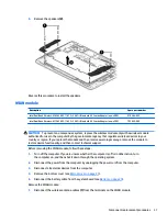
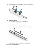
Remove the display panel assembly.
b.
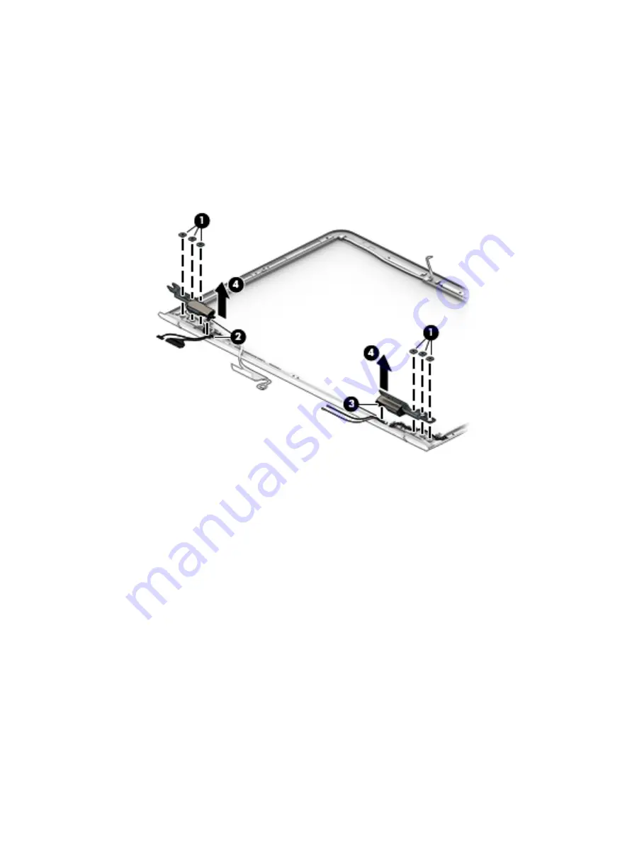
Remove the six Phillips PM2.0×2.4 broad head screws (1) that secure the display hinges to
the display back cover.
c.
Release the display panel cable and the webcam/microphone module cable from the opening (2) in
the display left hinge.
d.
Release the wireless antenna cables from the opening (3) in the display right hinge.
e.
Remove the display hinges (4).
The display hinges are available using spare part number 909631-001.
15.
If it is necessary to replace the wireless auxiliary antenna cable and transceiver:
a.
Remove the display panel assembly.
b.
Remove the display right hinge.
c.
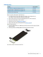
Remove the Phillips PM1.5×2.4 screw (1) that secures the vertical support bracket to
the display back cover.
d.
Release the retention tape (2) that secures the vertical support bracket and the wireless auxiliary
antenna cable to the display back cover.
e.
Remove the vertical support bracket (3).
f.
Detach the wireless auxiliary antenna transceiver (4) from the display back cover. (The wireless
auxiliary antenna transceiver is attached to the display back cover with double-sided adhesive.)
g.
Release the wireless auxiliary antenna cable from the retention clips (5) and routing channel built
into the top, right, and bottom edges of the display back cover.
Component replacement procedures
41
Содержание CTO 13t-ab000
Страница 4: ...iv Safety warning notice ...
Страница 7: ...11 Recycling 66 Index 67 vii ...
Страница 8: ...viii ...
Страница 23: ...Computer major components Computer major components 15 ...


