background image

7–14

437963-001

Service Reference Guide, dc5750

Removal and Replacement Procedures— Small Form Factor (SFF) Chassis

7.7.4 Hard Drive 

A Torx T-15 screwdriver is needed to remove and install the guide screws on a hard drive.

Ä

CAUTION: 

Make sure personal files on the hard drive are backed up to an external storage device 

before removing the hard drive. Failure to do so will result in data loss. After replacing the primary hard 

drive, you will need to run the 

Restore Plus!

 CD to load the HP factory-installed files.

Ä

CAUTION: 

To prevent loss of work and damage to the computer or drive:

If you are inserting or removing a hard drive, shut down the operating system properly, then turn off 

the computer. Do not remove a hard drive while the computer is on or in standby mode.

Before handling a drive, ensure that you are discharged of static electricity. While handling a drive, 

avoid touching the connector. Refer to 

Section 5.2, “Electrostatic Discharge Information”


for more 

information about preventing electrostatic damage.

Handle a drive carefully; do not drop it.

Do not use excessive force when inserting a drive.

Avoid exposing a hard drive to liquids, temperature extremes, or products that have magnetic fields 

such as monitors or speakers.

1. IPrepare the computer for disassembly (

Section 7.1

).

2. Remove the access panel (

Section 7.3

).

3. Remove the front bezel (

Section 7.4

).

4. Remove the optical drive if present (

Section 7.7.2

).

5. Remove the external 3.5-inch drive if present (

Section 7.7.3

).

6. Disconnect the power 

1

 and data 

2

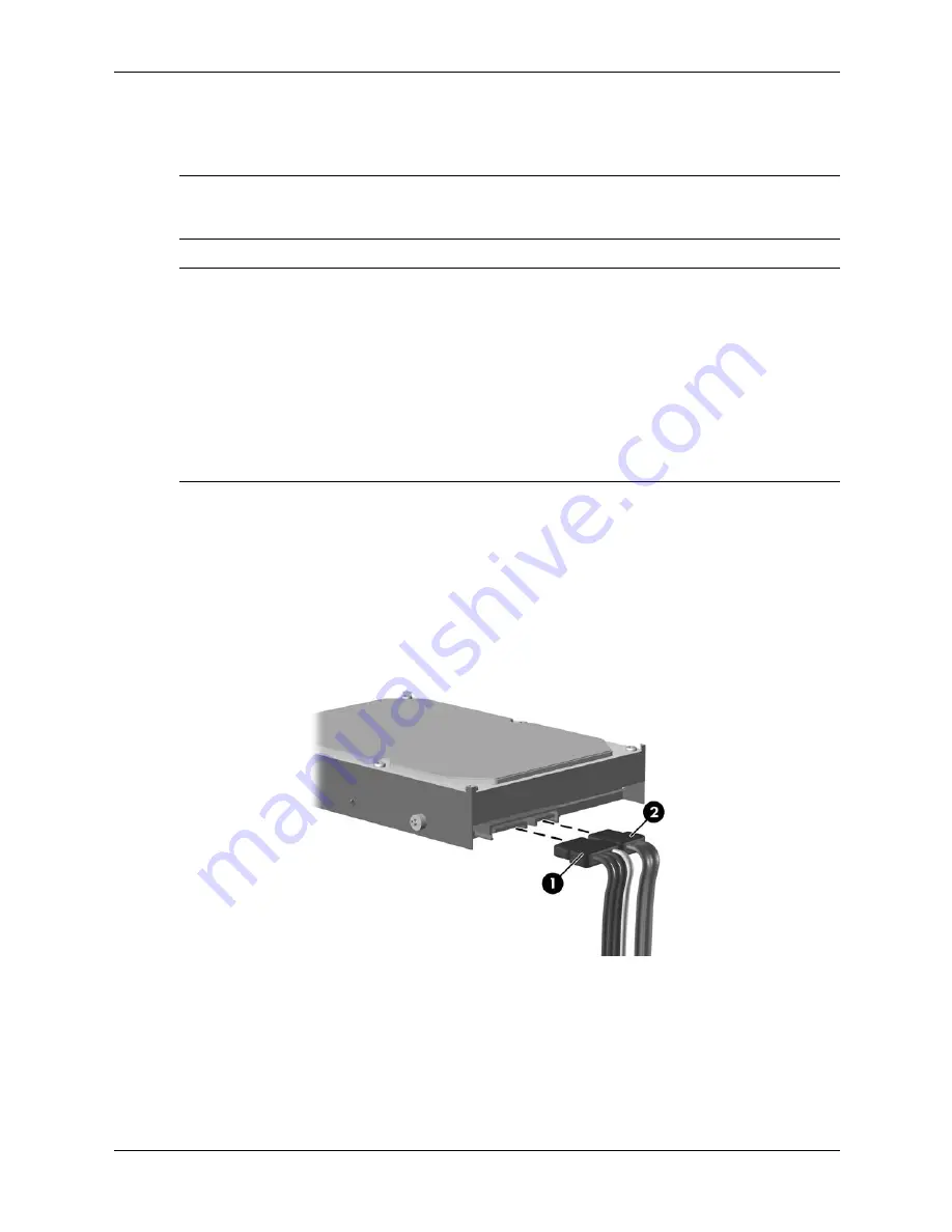
 cables from the back of the hard drive.

Содержание Compaq dc5750 MT

Страница 1: ...provides information on the removal and replacement of all parts as well as information on troubleshooting Desktop Management setup utilities SATA drives safety routine care connector pin assignments POST error messages and diagnostic indicator lights Document Part Number 437963 001 ...

Страница 2: ......

Страница 3: ...Service Reference Guide HP Compaq dc5750 Business PC 1st Edition Document Part Number 437963 001 November 2006 ...

Страница 4: ...warranty HP shall not be liable for technical or editorial errors or omissions contained herein This document contains proprietary information that is protected by copyright No part of this document may be photocopied reproduced or translated to another language without the prior written consent of Hewlett Packard Company ÅWARNING Text set off in this manner indicates that failure to follow direct...

Страница 5: ...Saving and Printing Information in HP Insight Diagnostics 2 18 2 3 8 Downloading the Latest Version of HP Insight Diagnostics 2 18 3 Desktop Management 3 1 Initial Configuration and Deployment 3 1 3 1 1 HP OpenView Agent 3 2 3 1 2 Altiris Deployment Solution Agent 3 2 3 1 3 HP Backup and Recovery Manager 3 2 3 2 Remote System Installation 3 3 3 3 Software Updating and Management 3 3 3 3 1 HP Clien...

Страница 6: ... Serial and Parallel ATA Drive Guidelines and Features 4 1 SATA Hard Drives 4 1 4 2 SATA Hard Drive Cables 4 2 4 2 1 SATA Data Cable 4 2 4 2 2 SATA Power Cable 4 2 4 3 PATA Device Information 4 3 4 4 ATA SMART Drives 4 3 4 5 Hard Drive Capacities 4 3 5 Identifying the Chassis Routine Care and Disassembly Preparation 5 1 Chassis Designations 5 1 5 1 1 Small Form Factor SFF 5 1 5 1 2 Microtower MT 5...

Страница 7: ... Drive Positions 6 15 6 9 2 Removing an External Drive 6 16 6 9 3 Installing an External Drive 6 18 6 9 4 Replacing an Internal Hard Drive 6 20 6 10Chassis Fan 6 25 6 11Front Shroud 6 26 6 12Front I O Panel Housing Assembly 6 27 6 13Heatsink 6 28 6 14Processor 6 29 6 15Speaker 6 31 6 16Power Supply 6 32 6 17System Board 6 33 6 18Battery 6 34 6 18 1Type 1 Battery Holder 6 35 6 18 2Type 2 Battery Ho...

Страница 8: ... 12Front I O Device 7 23 7 13Chassis Fan 7 24 7 14Power Switch Assembly 7 25 7 15Speaker 7 27 7 16Heatsink 7 28 7 17Processor 7 29 7 18System Board 7 31 7 19Battery 7 32 7 19 1Type 1 Battery Holder 7 33 7 19 2Type 2 Battery Holder 7 34 7 19 3Type 3 Battery Holder 7 35 A Connector Pin Assignments B Power Cord Set Requirements C POST Error Messages D Troubleshooting Without Diagnostics E System Boar...

Страница 9: ...ed with a Microsoft operating system some portions of this documentation do not apply For complete operating system installation and configuring instructions refer to the operating system documentation Additional information is available in online help Microsoft security updates are available on the Microsoft Web site 1 1 Installing or Upgrading Device Drivers To install optional hardware devices ...

Страница 10: ...izard then click Next 2 Select Create factory software recovery CDs or DVDs to recover the system 3 Follow the instructions in the wizard The HP Backup and Recovery Manager can be used to back up data and system files to the hard drive to network drives or to removable media such as CDs DVDs or flash media If data or system files are lost deleted or corrupted Backup and Recovery Manager allows you...

Страница 11: ...ish and manage passwords and other security features Establish and manage energy saving timeouts All features identified in this chapter may not be available on all HP products 2 1 Power On Self Test POST POST is a series of diagnostic tests that runs automatically when the system is turned on POST checks the following items to ensure that the computer system is functioning properly Keyboard Memor...

Страница 12: ...ayed regardless of the mode selected To manually switch to Post Messages Enabled during POST press any key except F1 through F12 Establish an Ownership Tag the text of which is displayed each time the system is turned on or restarted Enter the Asset Tag or property identification number assigned by the company to this computer Enable the power on password prompt during system restarts warm boots a...

Страница 13: ...guage from the list and press the Enter key 4 A choice of five headings appears in the Computer Setup Utilities menu File Storage Security Power and Advanced 5 Use the arrow left and right keys to select the appropriate heading Use the arrow up and down keys to select the option you want then press Enter To return to the Computer Setup Utilities menu press Esc 6 To apply and save changes select Fi...

Страница 14: ...to Removable Media Saves system configuration including CMOS to a formatted 1 44 MB diskette a USB flash media device or a diskette like device a storage device set to emulate a diskette drive Restore from Removable Media Restores system configuration from a diskette a USB flash media device or a diskette like device Default Setup Save Current Settings as Default Saves the current system configura...

Страница 15: ...ion Allows you to select a drive emulation type for a certain storage device For example a Zip drive can be made bootable by selecting diskette emulation Drive Type Emulation Options ATAPI Zip drive None treated as Other Diskette treated as diskette drive Legacy diskette No emulation options available CD ROM drive No emulation options available ATAPI LS 120 None treated as Other Diskette treated a...

Страница 16: ...ly when User translation mode is selected Allows you to specify the parameters logical cylinders heads and sectors per track used by the BIOS to translate disk I O requests from the operating system or an application into terms the hard drive can accept Logical cylinders may not exceed 1024 The number of heads may not exceed 256 The number of sectors per track may not exceed 63 These fields are on...

Страница 17: ...only applies when SATA emulation IDE Advanced operating systems like Windows may reenable the channel SATA 1 and 3 Allows you to enable or disable DOS and boot accesses to the Secondary channel of the first SATA controller This feature only applies when SATA emulation IDE Advanced operating systems like Windows may reenable the channel SATA 4 some models Allows you to enable or disable DOS and boo...

Страница 18: ... this one time Security Smart Card Options some models Allows you to enable disable the Smart Card to be used in place of the Power On Password Setup Password Allows you to set and enables setup administrator password If the setup password is set it is required to change Computer Setup options flash the ROM and make changes to certain plug and play settings under Windows Power On Password Allows y...

Страница 19: ...o identify the owner of the computer Chassis serial number or Universal Unique Identifier UUID number The UUID can only be updated if the current chassis serial number is invalid These ID numbers are normally set in the factory and are used to uniquely identify the system Keyboard locale setting for example English or German for System ID entry DriveLock Security Allows you to assign or modify a m...

Страница 20: ...e load does not require the full capabilities of the processor Idle Power Savings Extended Normal Allows certain operating systems to decrease the processors power consumption when the processor is idle ACPI S3 Hard Disk Reset Enabling this causes the BIOS to ensure hard disks are ready to accept commands after resuming from S3 before returning control to the operating system ACPI S3 PS2 Mouse Wak...

Страница 21: ...e system to attempt booting from the network Option ROM prompt enable disable Enabling this feature will cause the system to display a message before loading options ROMs This feature is supported on some models only Remote wakeup boot source remote server local hard drive After Power Loss off on previous state Set this option to Off causes the computer to remain powered off when power is restored...

Страница 22: ...s Allows you to set resources for or disable onboard system devices diskette controller serial port or parallel port PCI Devices Lists currently installed PCI devices and their IRQ settings Allows you to reconfigure IRQ settings for these devices or to disable them entirely These settings have no effect under an APIC based operating system PCI VGA Configuration Displayed only if there are multiple...

Страница 23: ...mpletely disable the network controller NIC by using the arrow left and right keys to select the Security Device Security menu Set the Network Controller option to Device Hidden This prevents the network controller from being used by the operating system and reduces the power used by the computer in S5 Processor cache enable disable Unique Sleep State Blink Patterns Allows you to choose an LED bli...

Страница 24: ...e current configuration of the computer From the Survey tab there is access to several categories of information about the computer Other tabs provide additional information including diagnostic test options and test results The information in each screen of the utility can be saved as an html file and stored on a diskette or USB HP Drive Key Use HP Insight Diagnostics to determine if all the devi...

Страница 25: ...ey Tab The Survey tab displays important system configuration information In the View level field you can select the Summary view to see limited configuration data or select the Advanced view to see all the data in the selected category In the Category field you can select the following categories of information to display All Gives a listing of all categories of information about the computer Ove...

Страница 26: ...ring tests that require your interaction You may also determine whether the test passed or failed Unattended Mode Does not display prompts and requires no interaction If errors are found they are displayed when testing is complete To begin testing 1 Select the Test tab 2 Select the tab for the type of test to be run Quick Complete or Custom 3 Select the Test Mode Interactive or Unattended 4 Choose...

Страница 27: ... Clear Test Log button will clear the contents of the Test Log The Error Log displays the tests for devices that have failed during the diagnostic testing and includes the following columns of information The Device section displays the device tested The Test section displays the type of test run The Description section describes the error that the diagnostic test found The Recommended Repair will...

Страница 28: ...lick the Save button An html file will be saved to the inserted diskette or USB HP Drive Key Do not remove the diskette or Drive Key until you see a message indicating that the total file has been written to the media 5 Print the information from the storage device used to save it To exit HP Insight Diagnostics click the Exit Diagnostics button in the bottom left corner of the screen then remove t...

Страница 29: ...ed A customized software image may be deployed by Installing additional software applications after unbundling the preinstalled software image Using software deployment tools such as HP OpenView Client Configuration Manager HP OpenView PC Configuration Management Solutions or Altiris Deployment Solution to replace the preinstalled software with a customized software image Using a disk cloning proc...

Страница 30: ...ftware Setup 4 Click Next 5 Scroll down and click on the link to install Altiris AClient 3 1 3 HP Backup and Recovery Manager HP Backup and Recovery Manager can create the Restore Plus CD set This set includes the Restore Plus CD the Operating system CD and any Supplemental Software CDs ÄCAUTION The Restore Plus CD set will not include any system settings or user data created after the initial sys...

Страница 31: ...o PXE boot 3 3 Software Updating and Management HP provides several tools for managing and updating software on desktops workstations and notebooks HP Client Manager Interface HP System Software Manager HP Client Manager HP ProtectTools Security Manager HP Client Premium Suite HP Client Foundation Suite HP OpenView Client Configuration Manager HP OpenView PC Configuration Management Solutions HP P...

Страница 32: ...ically updates any down revision system software on the networked PCs to the later levels available in the file store Since SSM only allows distribution of SoftPaq updates to the correct client system models administrators can confidently and efficiently use SSM to keep system software updated System Software Manager integrates with enterprise software distribution tools such as Microsoft Systems ...

Страница 33: ...pending on your model For example Embedded Security for ProtectTools requires that the Trusted Platform Module TPM embedded security chip some models only be installed on your computer and Smart Card Security for ProtectTools requires an optional smart card and reader ProtectTools modules may be preinstalled preloaded or available for purchase from the HP Web site Visit http www hp com products se...

Страница 34: ...maangement for HP Thin Clients For more information about the HP OpenView Client Configuration Manager visit http www managementsoftware hp com products ccm index html 3 3 8 HP OpenView PC Configuration Management Solutions HP OpenView Configuration Management solutions automate the management of software such as operating systems applications patches content and configuration settings to ensure t...

Страница 35: ... subhub php 3 3 1 1 Retired Solutions Two software packages Altiris Local Recovery and Dantz Retrospect will no longer be shipping on HP business desktops notebooks or workstations Starting with new business desktops notebooks and workstations released in 2006 all will ship with HP Backup and Recovery Manager 3 4 ROM Flash The computer s BIOS is stored in a programmable flash ROM read only memory ...

Страница 36: ...anagement The computer must be powered on or turned on through Remote Wakeup to take advantage of Remote ROM Flash For more information on Remote ROM Flash refer to the HP Client Manager or System Software Manager at http h18000 www1 hp com im prodinfo html ...

Страница 37: ... the system BIOS image is not valid a failsafe Boot Block BIOS provides enough support to search removable media for BIOS image files If an appropriate BIOS image file is found it is automatically flashed into the ROM When an invalid system BIOS image is detected the system power LED will blink red 8 times one blink every second Simultaneously the speaker will beep 8 times If the portion of the sy...

Страница 38: ...rt it now 3 Turn on the computer 4 As soon as the computer is turned on press F10 when the monitor light turns green to enter Computer Setup Press Enter to bypass the title screen if necessary If you do not press F10 at the appropriate time you must restart the computer and again press F10 when the monitor light turns green to access the utility 5 If you are using a a diskette insert it now 6 Sele...

Страница 39: ...be used 2 Select a setup configuration to copy Turn off the computer If you are in Windows click Start Shut Down Shut Down 3 If you are using a USB flash media device insert it now 4 Turn on the computer 5 As soon as the computer is turned on press F10 when the monitor light turns green to enter Computer Setup Press Enter to bypass the title screen if necessary If you do not press F10 at the appro...

Страница 40: ...COM or FORMAT COM into a diskette drive and turn on the computer to boot to the DOS diskette 4 Run FDISK from the A prompt by typing FDISK and pressing Enter If prompted click Yes Y to enable large disk support 5 Enter Choice 5 to display the drives in the system The USB flash media device will be the drive that closely matches the size of one of the drives listed It will usually be the last drive...

Страница 41: ...SB flash media device you must have USB flash media device Bootable DOS diskette with the FDISK and SYS programs If SYS is not available FORMAT may be used but all existing files on the USB flash media device will be lost PC that is bootable from a USB flash media device ÄCAUTION Some older PCs may not be bootable from a USB flash media device If the default boot order in the Computer Setup F10 Ut...

Страница 42: ...er Computer Setup Press Enter to bypass the title screen if necessary 15 Go to Advanced PCI Devices and re enable the PATA and SATA controllers that were disabled in step 6 Put the SATA controller on its original IRQ 16 Save the changes and exit The computer will boot to the USB flash media device as drive C The default boot order varies from computer to computer and it can be changed in the Compu...

Страница 43: ...OM images needed to run the latest Microsoft Windows operating system on the HP computer 3 4 7 Industry Standards HP management solutions integrate with other systems management applications and are based on industry standards such as Web Based Enterprise Management WBEM Windows Management Interface WMI Wake on LAN Technology ACPI SMBIOS Pre boot Execution PXE support 3 5 Asset Tracking and Securi...

Страница 44: ... the computer locally through the Computer Setup F10 Utilities Security Features Overview Option Description Setup Password Allows you to set and enable setup administrator password If the setup password is set it is required to change Computer Setup options flash the ROM and make changes to certain plug and play settings under Windows Power On Password Allows you to set and enable power on passwo...

Страница 45: ...rial number is invalid These ID numbers are normally set in the factory and are used to uniquely identify the system Keyboard locale setting for example English or German for System ID entry DriveLock some models Allows you to assign or modify a master or user password for certain ATA hard drives When this feature is enabled the user is prompted to provide one of the DriveLock passwords during POS...

Страница 46: ...word is entered 1 Turn on or restart the computer If you are in Windows click Start Shut Down Restart 2 As soon as the computer is turned on press F10 when the monitor light turns green to enter Computer Setup Press Enter to bypass the title screen if necessary If you do not press F10 at the appropriate time you must restart the computer and again press F10 when the monitor light turns green to ac...

Страница 47: ...click Start Shut Down Restart 2 When the key icon appears on the monitor type the current password then press Enter Type carefully for security reasons the characters you type do not appear on the screen If you enter the password incorrectly a broken key icon appears Try again After three unsuccessful tries you must turn off the computer then turn it on again before you can continue Entering a Set...

Страница 48: ... effect the next time you turn on the computer Refer to National Keyboard Delimiter Characters for information about the alternate delimiter characters The power on password and setup password may also be changed using the Security options in Computer Setup Deleting a Power On or Setup Password If the system is equipped with an embedded security device refer to the HP ProtectTools Security Manager...

Страница 49: ...n compared with the damage that could result from unauthorized access to its contents In order to balance this level of security with the practical need to accommodate a forgotten password the HP implementation of DriveLock employs a two password security scheme One password is intended to be set and used by a system administrator while the other is typically set and used by the end user There is ...

Страница 50: ...instructed to cycle power DriveLock Applications The most practical use of the DriveLock security feature is in a corporate environment The system administrator would be responsible for configuring the hard drive which would involve among other things setting the DriveLock master password and a temporary user password In the event that the user forgets the user password or the equipment is passed ...

Страница 51: ... desired security level 4 Before exiting select File Save Changes and Exit Smart Cover Lock The Smart Cover Lock is a software controllable cover lock featured on some HP computers This lock prevents unauthorized access to the internal components Computers ship with the Smart Cover Lock in the unlocked position ÄCAUTION For maximum cover lock security be sure to establish a setup password The setu...

Страница 52: ... F10 at the appropriate time you must restart the computer and again press F10 when the monitor light turns green to access the utility 3 Select Security Smart Cover Cover Lock Unlock 4 Before exiting select File Save Changes and Exit Using the Smart Cover FailSafe Key If you enable the Smart Cover Lock and cannot enter your password to disable the lock you will need a Smart Cover FailSafe Key to ...

Страница 53: ...iled tests 3 6 1 Drive Protection System The Drive Protection System DPS is a diagnostic tool built into the hard drives installed in some HP computers DPS is designed to help diagnose problems that might result in unwarranted hard drive replacement When HP computers are built each installed hard drive is tested using DPS and a permanent record of key information is written onto the drive Each tim...

Страница 54: ...3 26 437963 001 Service Reference Guide dc5750 Desktop Management ...

Страница 55: ...ication of the attach rules a POST error message may be displayed Serial ATA Hard Drive Characteristics Number of pins conductors in data cable 7 7 Number of pins in power cable 15 Maximum data cable length 39 37 in 100 cm Data interface voltage differential 400 700 mV Drive voltages 3 3 V 5V 12 V Jumpers for configuring drive N A Data transfer rate 3 0 Gb s SATA Identification Color Port Attachme...

Страница 56: ...igned to transmit data for only a single drive As shown in the table each cable has 3 grounds and 4 transmit receive pins 4 2 2 SATA Power Cable Pin Number Usage Device Plug Host Plug P1 Ground Ground Ground P2 A Transmit data Receive data P3 A Transmit data Receive data P4 Ground Ground Ground P5 B Receive data Transmit data P6 B Receive data Transmit data P7 Ground Ground Ground P2 and P3 differ...

Страница 57: ...ies The combination of the file system and the operating system used in the computer determines the maximum usable size of a drive partition A drive partition is the largest segment of a drive that may be properly accessed by the operating system A single hard drive may therefore be subdivided into a number of unique drive partitions in order to make use of all of its space Because of the differen...

Страница 58: ...4 4 437963 001 Service Reference Guide dc5750 Serial and Parallel ATA Drive Guidelines and Features ...

Страница 59: ...ence to the procedures and precautions described in this chapter is essential for proper service Ä CAUTION When the computer is plugged into an AC power source voltage is always applied to the system board You must disconnect the power cord from the power source before opening the computer to prevent system board or component damage 5 1 Chassis Designations 5 1 1 Small Form Factor SFF ...

Страница 60: ...5 2 437963 001 Service Reference Guide dc5750 Identifying the Chassis Routine Care and Disassembly Preparation 5 1 2 Microtower MT ...

Страница 61: ...rcuitry design and structure determine the degree of sensitivity The following packaging and grounding precautions are necessary to prevent damage to electric components and accessories To avoid hand contact transport products in static safe containers such as tubes bags or boxes Protect all electrostatic parts and assemblies with conductive or approved containers or packaging Keep electrostatic s...

Страница 62: ...surface and properly grounded tools and equipment Use static dissipative mats foot straps or air ionizers to give added protection Handle electrostatic sensitive components parts and assemblies by the case or PCB laminate Handle them only at static free work areas Turn off power and input signals before inserting and removing connectors or test equipment Use fixtures made of static safe materials ...

Страница 63: ...p unit as this also restricts airflow Occasionally clean the air vents on all vented sides of the computer Lint dust and other foreign matter can block the vents and limit the airflow Be sure to unplug the computer before cleaning the air vents If operating in a dusty environment periodic cleaning of heatsink and fans is recommended t oprevent overheating Never operate the computer with the cover ...

Страница 64: ...computer Lint and other foreign matter can block the vents and limit the airflow 5 4 3 Cleaning the Keyboard Follow all safety precautions in Section 5 4 1 before cleaning the keyboard To clean the tops of the keys or the keyboard body follow the procedures described in Section 5 4 2 When cleaning debris from under the keys review all rules in Section 5 4 1 before following these procedures Ä CAUT...

Страница 65: ...5 4 2 5 5 Service Considerations Listed below are some of the considerations that you should keep in mind during the disassembly and assembly of the computer 5 5 1 Power Supply Fan The power supply fan is a variable speed fan based on the temperature in the power supply Ä CAUTION The cooling fan is always on when the computer is in the On mode The cooling fan is off when the computer is in Standby...

Страница 66: ...aught or snagged by parts being removed or replaced Ä CAUTION When servicing this computer ensure that cables are placed in their proper location during the reassembly process Improper cable placement can damage the computer 5 5 5 Hard Drives Handle hard drives as delicate precision components avoiding all physical shock and vibration This applies to failed drives as well as replacement spares If ...

Страница 67: ...replacement procedures Å WARNING This computer contains a lithium battery There is a risk of fire and chemical burn if the battery is handled improperly Do not disassemble crush puncture short external contacts dispose in water or fire or expose it to temperatures higher than 140ºF 60ºC Do not attempt to recharge the battery N Batteries battery packs and accumulators should not be disposed of toge...

Страница 68: ...5 10 437963 001 Service Reference Guide dc5750 Identifying the Chassis Routine Care and Disassembly Preparation ...

Страница 69: ...rating system 4 Remove any diskette or compact disc from the computer 5 Turn off the computer and any peripheral devices that are connected to it Ä CAUTION Turn off the computer before disconnecting any cables Ä CAUTION Regardless of the power on state voltage is always present on the system board as long as the system is plugged into an active AC outlet In some systems the cooling fan is on even ...

Страница 70: ...edures Microtower MT Chassis 6 2 External Security Devices 6 2 1 Installing a Cable Lock The cable lock may be used to secure the computer access panel to the chassis and at the same time secure the computer to a fixed object Insert the cable lock in the location shown below ...

Страница 71: ...al and Replacement Procedures Microtower MT Chassis 6 2 2 Installing a Padlock A padlock may be used by itself to secure the access panel to the computer chassis A padlock may also be used with a security cable to secure the computer to a fixed object I ...

Страница 72: ... computer is turned off and that the power cord is disconnected from the electrical outlet 2 Loosen the captive thumbscrew 1 that secures the access panel to the computer chassis 3 Slide the access panel 2 back about 1 3 cm 1 2 inch then lift it off the unit You may want to lay the computer on its side to install internal parts Be sure the side with the access panel is facing up To install the acc...

Страница 73: ...ont Bezel 1 Prepare the computer for disassembly Section 6 1 2 Remove the access panel Section 6 3 3 To remove the front bezel press the green latch on the bottom right of the chassis 1 to release the bottom of the bezel then swing the bottom of the bezel away from the chassis 2 to release the top of the bezel ...

Страница 74: ...r MT Chassis To reinstall the front bezel 1 Position the chassis in the upright position 2 Insert the two hooks on the top of the bezel into the rectangular holes on the chassis 1 then rotate the bottom of the bezel onto the chassis 2 so that the bottom two hooks on the bezel snap into place ...

Страница 75: ...g or installing a front drive bezel 1 Prepare the computer for disassembly Section 6 1 2 Remove the access panel Section 6 3 3 Remove the front bezel Section 6 4 4 Press the two retaining tabs on the inside of the bezel towards the outer edge of the bezel 1 and pull the bezel blank inwards to remove it 2 To install a bezel blank reverse the removal procedure ...

Страница 76: ...e flat ribbon cables come prefolded Never change the folds on these cables Do not bend any cable sharply A sharp bend can break the internal wires Never bend a SATA data cable tighter than a 30 mm 1 18 in radius Never crease a SATA data cable Do not rely on components like the drive cage power supply or computer cover to push cables down into the chassis Always position the cables to lay properly ...

Страница 77: ...Diskette drive P9 Cable To PCA Designator Front power button LED System board P5 Speaker System board P6 White Chassis fan System board P9 Red Diskette drive System board P10 FLOPPY Black Second ODD Audio cable System board P1 1 AUX if required Front I O USB System board P24 Yellow Serial port B System board P52 1st SATA Hard drive System board P60 SATA 0 Dark Blue 1st ODD or 2nd Hard drive if no ...

Страница 78: ... Remove the access panel and rotate the computer so the system board is parallel to the table to make it easier to work on Section 6 3 ÅWARNING To reduce risk of personal injury from hot surfaces allow the internal system components to cool before touching 3 Open both latches of the memory module socket 1 and insert the memory module into the socket 2 Refer to Appendix F Memory for the correct seq...

Страница 79: ...ve the access panel and rotate the computer so the system board is parallel to the table to make it easier to work on Section 6 3 3 On the rear of the computer a sliding slot cover lock secures the expansion card brackets and expansion slot covers in place Remove the captive thumbscrew that holds the slot cover lock in place 1 and slide the slot cover lock up and off the chassis 2 ...

Страница 80: ... expansion card in a vacant socket remove the appropriate expansion slot cover on the back of the chassis Pull the slot cover straight up from the socket then away from the inside of the chassis b If removing a standard PCI expansion card hold the card at each end and carefully rock it back and forth until the connectors pull free from the socket Pull the expansion card straight up from the socket...

Страница 81: ...om the inside of the chassis to release it from the chassis frame Be sure not to scrape the card against the other components 5 Store the removed card in anti static packaging 6 If not replacing the old expansion card with a new expansion card install an expansion slot cover to close the open slot Insert the metal slot cover in the opened slot and slide the slot cover lock down to secure the slot ...

Страница 82: ... the system board 2 When installing an expansion card press firmly on the card so that the whole connector seats properly in the expansion card slot 8 If you are replacing an expansion card store the old card in the anti static packaging that contained the new card 9 While holding the expansion card bracket against the chassis slide the slot cover lock down toward the expansion card brackets and s...

Страница 83: ...ure personal files on the hard drive are backed up to an external storage device before removing the hard drive Failure to do so will result in data loss After replacing the primary hard drive you will need to run the Restore Plus CD to load the HP factory installed files 6 9 1 Drive Positions Drive Positions Item Description 1 Two 5 25 inch half height bays for optional drives optical drives show...

Страница 84: ...omputer for disassembly Section 6 1 3 Remove the access panel and rotate the computer so the system board is parallel to the table to make it easier to work on Section 6 3 4 Remove the front bezel Section 6 4 5 Disconnect the power and data cables from the back of the drive as shown in the following illustrations Disconnecting Optical Drive Cables Some products use straight cable connectors while ...

Страница 85: ... Releasing the Drives 6 A latch drive bracket with release tabs secures the drives in the drive bay Lift the release tab on the latch drive bracket 1 for the drive you want to remove then slide the drive from its drive bay 2 7 Remove the four guide screws two on each side from the old drive You will need these screws to install a new drive ...

Страница 86: ... drive Avoid exposing a hard drive to liquids temperature extremes or products that have magnetic fields such as monitors or speakers An optical drive is a CD ROM CD R RW DVD ROM DVD R RW or CD RW DVD Combo drive The system does not support Parallel ATA PATA optical drives 1 Install four guide screws two on each side into the new drive The screws help guide the drive into its proper position in th...

Страница 87: ...uide slots until the drive snaps into place 3 Reconnect the power and data cables to the drive as shown in the following illustrations Refer to Chapter 4 Serial and Parallel ATA Drive Guidelines and Features for information on attaching the cabling to get optimum performance Connecting Optical Drive Cables Some products use straight cable connectors while others use right angle connectors ...

Страница 88: ...or drive If you are inserting or removing a hard drive shut down the operating system properly then turn off the computer Do not remove a hard drive while the computer is on or in standby mode Before handling a drive ensure that you are discharged of static electricity While handling a drive avoid touching the connector Refer to Section 5 2 Electrostatic Discharge Information for more information ...

Страница 89: ...Microtower MT Chassis 4 Remove the front bezel Section 6 4 5 Disconnect the power 1 and data 2 cables from the back of the drive 6 Remove the power cable 1 and primary data cable 2 and secondary data cable if necessary 3 from the cable retainers to make it easier to access the drive ...

Страница 90: ...rew two on each side that were removed from the old drive into the new drive The screws help guide the drive into its proper position in the bay Extra guide screws atre provided on the front of the chassis under the front bezel There are a total of eight extra guide screws on the front of the chassis Four have 6 32 standard threads and four have M3 metric threads Standard screws are used for hard ...

Страница 91: ... upper bay is for the primatry hard drive The bottom bay is for the optional secondary hard drive 11 Connect the power 1 and data 2 cables to the back of the hard drive If you are installing a primary hard drive use the power connector labeled P5 If you are installing a secondary hard drive use the power cable labeled P4 12 If installing a new drive connect the oppposite end of the data cable to t...

Страница 92: ...vailable unpopulated SATA connector in the system board in the following order SATA0 SATA1 SATA3 SATA2 13 Route the power and data cables into their cable retainers 14 Replace the front bezel and computer access panel 15 Reconnect the power cord and any external devices then turn on the computer If you replaced the primary hard drivem use the Restore Plus CD set that was created when starting the ...

Страница 93: ...the access panel and rotate the computer so the system board is parallel to the table to make it easier to work on Section 6 3 3 Disconnect the power cable that connects the chassis fan to the system board 1 4 Remove the four screws from the exterior rear of the chassis that secure the fan 2 5 Remove the fan from the chassis To install the chassis fan reverse the removal procedure ...

Страница 94: ...the access panel and rotate the computer so the system board is parallel to the table to make it easier to work on Section 6 3 3 Remove the hard drive cables from the plastic shroud at the front of the chassis and from the hard drives 4 Lift the shroud straight up 1 about 5 mm 3 16 in before pulling it into the chassis 2 to remove it To install the shroud reverse the removal process ...

Страница 95: ... the plastic shroud at the front of the chassis and from the hard drives 4 Remove the shroud from the chassis Section 6 11 5 Disconnect the power switch LED cable the front USB cable and the front audio cable from the system board 6 Remove the single screw that secure the housing to the chassis 1 then push the housing to the inside of the chassis 2 To install the housing assembly reverse the remov...

Страница 96: ... even the downward forces on the processor This is especially important as the pins on the socket are very fragile and any damage to them may require replacing the system board 5 Lift the heatsink from atop the processor 2 and set it on its side to keep from contaminating the work area with thermal grease When reinstalling the heatsink make sure that its bottom has been cleaned with an alcohol wip...

Страница 97: ...g heatsink go to step 1 If using a new heatsink go to step 4 1 If reusing the existing heatsink clean the bottom of the heatsink with the alcohol pad provided in the spares kit ÄCAUTION Before reinstalling the heatsink you must clean the top of the processor and the bottom of the heatsink with an alcohol pad supplied in the spares kit After the alcohol has evaporated apply thermal grease to the to...

Страница 98: ...t the heatsink on the processor This is especially important as the pins on the socket are very fragile and any damage to them may require replacing the system board After installing a new processor onto the system board always update the system ROM to ensure that the latest version of the BIOS is being used on the computer The latest system BIOS can be found on the Web at http h18000 www1 hp com ...

Страница 99: ...ove the hard drive cables from the plastic shroud at the front of the chassis and from the hard drives 4 Remove the shroud from the chassis Section 6 11 5 Disconnect the speaker wire from the system board connector 6 Remove the two screws 1 that secure the speaker to the chassis 7 Remove the speaker by lifting it up 2 and out of the retaining clips To install the speaker reverse the removal proced...

Страница 100: ... and or the AC outlet before opening the computer 1 Prepare the computer for disassembly Section 6 1 2 Remove the access panel and rotate the computer so the system board is parallel to the table to make it easier to work on Section 6 3 3 Disconnect all power cables from the mass storage devices and from the system board 4 Remove the screws that connect the power supply to the chassis 1 5 Pull the...

Страница 101: ...the system board is parallel to the table to make it easier to work on Section 6 3 3 Remove all PCI expansion cards Section 6 8 4 Disconnect all cables connected to the system board noting their location for reinstallation 5 Remove the six screws that secure the system board to the chassis 1 then slide the system board towards the front of the chassis to remove it 2 To install the system board rev...

Страница 102: ...roduct Ä CAUTION Before replacing the battery it is important to back up the computer CMOS settings When the battery is removed or replaced the CMOS settings will be cleared Refer to the Computer Setup F10 Utility Guide for information on backing up the CMOS settings N Batteries battery packs and accumulators should not be disposed of together with the general household waste In order to forward t...

Страница 103: ...e the replacement battery into position positive side up 3 The battery holder automatically secures the battery in the proper position 4 Replace the computer access panel Section 6 3 5 Plug in the computer and turn on power to the computer 6 Reset the date and time your passwords and any special system setups using Computer Setup Refer to the Computer Setup F10 Utility Guide ...

Страница 104: ...lift it out 1 2 To insert the new battery slide one edge of the replacement battery under the holder s lip with the positive side up 2 Push the other edge down until the clamp snaps over the other edge of the battery 3 Replace the computer cover or access panel Section 6 3 4 Plug in the computer and turn on power to the computer 5 Reset the date and time your passwords and any special system setup...

Страница 105: ... clip 1 that holds the battery in place then remove the battery 2 2 Insert the new battery and position the clip back in place 3 Replace the computer access panel Section 6 3 4 Plug in the computer and turn on power 5 Reset the date and time your passwords and any special system setups using Computer Setup Refer to the Computer Setup F10 Utility Guide ...

Страница 106: ...6 38 437963 001 Service Reference Guide dc5750 Removal and Replacement Procedures Microtower MT Chassis ...

Страница 107: ...ng the computer 4 Remove any diskette or compact disc from the computer 5 Turn off the computer and any peripheral devices that are connected to it Ä CAUTION Turn off the computer before disconnecting any cables Ä CAUTION Regardless of the power on state voltage is always present on the system board as long as the system is plugged into an active AC outlet In some systems the cooling fan is on eve...

Страница 108: ... cable lock may be used to secure the access panel to the chassis and at the same time secure the computer to a fixed object Insert the cable lock in the location shown below 7 2 2 Padlock A padlock may be used by itself to secure the access panel to the computer chassis A padlock may also be used with a security cable to secure the computer to a fixed object I ...

Страница 109: ...ION Before removing the access panel ensure that the computer is turned off and that the power cord is disconnected from the electrical outlet 1 Push down on the button 1 to release the latch that secures the access panel to the computer chassis 2 Slide the access panel back 2 about 1 3 cm 1 2 inch then lift it off the chassis To install the access panel reverse the removal procedure ...

Страница 110: ...ssis 7 4 Front Bezel 1 Prepare the computer for disassembly Section 7 1 2 Remove the access panel Section 7 4 3 Press the green latch behind the upper right side of the bezel 1 and pull the right side of the bezel off the chassis 2 then the left side To install the afront bezel reverse the removal procedure ...

Страница 111: ...ssembly Section 7 1 2 Remove the access panel Section 7 3 3 Remove the drive bezel by pushing the two retaining tabs that hold the bezel in place towards the outer left edge of the bezel 1 and pull the bezel blank inwards to remove it 2 The drive bezel will vary depending on the computer configuration Install a bezel or a bezel blank by pushing the bezel into place ...

Страница 112: ... position When folding a flat ribbon cable never fold to a sharp crease Sharp creases may damage the wires Some flat ribbon cables come prefolded Never change the folds on these cables Do not bend any cable sharply A sharp bend can break the internal wires Never bend a SATA data cable tighter than a 30 mm 1 18 in radius Never crease a SATA data cable Do not rely on components like the drive cage p...

Страница 113: ...upply SATA Optical drive P6 Power Supply Diskette drive P7 Power Supply SATA Optical drive P6 Cable To PCA Designator Front LED Power System board P5 Speaker System board P6 SPKR Chassis fan System board P8 F CHASSIS FAN Diskette drive System board P10 FLOPPY Black Front audio System board P23 FRNT AUD Blue Front I O USB System board P24 FRONT USB Yellow Serial port B System board P52 COM B 1st SA...

Страница 114: ... primary hard drive you will need to run the Restore Plus CD to load the HP factory installed files 7 7 1 Drive Positions To verify the type and size of the storage device installed in the computer run Computer Setup Drive Positions Item Description Item Description 1 5 25 inch external drive bay for optional drives Optical drive shown 3 3 5 inch internal hard drive bay 2 3 5 inch external drive b...

Страница 115: ...puter An optical drive is a CD ROM CD R RW DVD ROM DVD R RW or CD RW DVD Combo drive 1 Prepare the computer for disassembly Section 7 1 2 Remove the access panel Section 7 3 3 Remove the front bezel Section 7 4 4 Disconnect the power 1 cable and data 2 cables from the rear of the optical drive 5 Press down on the lever to the left of the drive 1 slide the drive back until it stops and lift it stra...

Страница 116: ...n the front of the chassis under the front bezel The M3 metric guide screws are black ÄCAUTION Use only 5 mm long scres as guide screws Longer screws can damage the internal components of the drive When replacing the drive transfer the four M3 metric guide screws from the old drive to the new one 7 Align the guide screws on the drive with the slots on the chassis Slide the drive all the way down 1...

Страница 117: ...1 7 1 1 Removal and Replacement Procedures Small Form Factor SFF Chassis 8 Connect the power 1 cable and data 2 cables to the rear of the optical drive 9 Complete the installation of the drive by reversing the remainder of the removal process ...

Страница 118: ... 7 1 2 Remove the access panel Section 7 3 3 Remove the front bezel Section 7 4 4 Remove the optical drive Section 7 7 2 5 Disconnect the data 1 and power 2 cables from the drive The other end of the cables should remain connected to the system board Diskette drive is shown 6 Press down on the lever to the left of the drive 1 slide the drive back until it stops and lift it straight up 2 ...

Страница 119: ...e of the drive down slightly 1 so that the top lip of the guide screws are not caught behind the metal frame the pull the drive out of the drive bay 2 To replace the drive reverse the removal procedure When replacing the drive transfer the four metric screws from the old drive to the new one The screws take the place of drive rails ...

Страница 120: ...urn off the computer Do not remove a hard drive while the computer is on or in standby mode Before handling a drive ensure that you are discharged of static electricity While handling a drive avoid touching the connector Refer to Section 5 2 Electrostatic Discharge Information for more information about preventing electrostatic damage Handle a drive carefully do not drop it Do not use excessive fo...

Страница 121: ...e lever to the left of the hard drive 1 slide the drive back until it stops and lift it straight up 2 8 Tilt the left side of the hard drive down slightly 1 so that the top lips of the guide screws are not caught behind the metal frame then pull the drive out of the drive bay 2 To install a hard drive reverse the removal procedure ...

Страница 122: ...placing the hard drive transfer the four screws from the old drive to the new one You will need a Torx T15 screwdriver to remove and re install the guide screws HP has provided four extra 6 32 standard guide screws on the front of the chassis under the front bezel The 6 32 standard guide screws are silver If you replaced the primary hard drive insert the Restore Plus CD to restore the operating sy...

Страница 123: ...unded metal object Refer to Section 5 2 Electrostatic Discharge Information for more information ÄCAUTION When handling a memory module be careful not to touch any of the contacts Doing so may damage the module 1 Prepare the computer for disassembly Section 7 1 2 Remove the access panel Section 7 3 3 Remove the front bezel Section 7 4 4 Remove the ODD Section 7 7 2 ÅWARNING To reduce risk of perso...

Страница 124: ... socket ensuring that the module is fully inserted and properly seated Make sure the latches are in the closed position 3 8 Repeat steps 4 and 5 for any additional modules that you want to install The computer automatically recognizes the additional memory when the computer is turned on To reassemble the computer reverse the removal procedure If you normally lock the Smart Cover Lock use Computer ...

Страница 125: ... the operating system then turn off any external devices 2 Disconnect the power cord from the power outlet and disconnect any external devices 3 Remove the access panel Section 7 3 4 Remove the slot cover retainer that secures the slot covers by lifting the retainer up then out and away from the chassis 5 Remove the slot cover by pulling it straight up and then back towards the inside of the chass...

Страница 126: ...is to release it from the chassis frame Be sure not to scrape the card against the other components 7 If you are removing a PXCI Express x16 crd pull the retention arm on the back of the expansion socket away from the card and carefully rock it back and forth until the connectors pull free from the socket Pull the card straight up from the socket then back towards the inside of the chassis to rele...

Страница 127: ... disconnected from the computer and or the AC outlet before opening the computer 1 Prepare the computer for disassembly Section 7 1 2 Remove the access panel Section 7 3 3 Disconnect the power cables from all of the drives 4 Disconnect the power cables from the system board 5 Disconnect the data cable from the rear of the optical drive 6 Lift the green locking lever 1 and slide the power supply to...

Страница 128: ...repare the computer for disassembly Section 7 1 2 Remove the access panel Section 7 3 3 Remove all cables that are attached to the fan shroud 1 4 Lift up on the fan shroud 2 to remove it from the computer To replace the shroud reverse the removal procedures When replacing the shroud make sure that it does not get caught on any wires ...

Страница 129: ...tion 7 3 3 Remove the fan shroud Section 7 11 4 Remove the optical drive Section 7 7 2 5 Rotate the optical drive retainer to its upright position to access the memory module sockets 6 Remove the two screws that secure the front I O device to the chassis 1 7 Push the front I O device into the chassis 2 and disconnect the cables from the system board To reinstall the front I O device reverse the re...

Страница 130: ...the computer for disassembly Section 7 1 2 Remove the access panel Section 7 3 3 Remove the fan shroud Section 7 11 4 Disconnect the chassis fan power cable from the system board 5 Remove the four screws that secure the chassis fan to the front of the chassis 1 then remove the fan 2 To install the chassis fan reverse the remocal procedures ...

Страница 131: ... 14 Power Switch Assembly 1 Prepare the computer for disassembly Section 7 1 2 Remove the access panel Section 7 3 3 Remove the fan shroud Section 7 11 4 Remove the optical drive Section 7 7 2 5 Rotate the optical drive retainer to its upright position 6 Disconnect the power switch LED cable from the system board ...

Страница 132: ...cedures Small Form Factor SFF Chassis 7 Squeeze the switch holder retaining clips together at the front of the chassis 1 and push the switch assembly out of the chassis 2 Push the two LEDs out of the chassis 3 To install the power switch and LEDs reverse the removal procedure ...

Страница 133: ...the computer for disassembly Section 7 1 2 Remove the access panel Section 7 3 3 Remove the fan shroud Section 7 11 4 Disconnect the speaker wire from the system board 5 Remove the two screws that secure the speaker to the chassis 1 then lift the speaker up and out of the chassis 2 To install the speaker reverse the removal procedures ...

Страница 134: ...et are very fragile and any damage to them may require replacing the system board 5 Lift the heatsink from atop the processor 2 and set it on its side to keep from contaminating the work area with thermal grease When reinstalling the heatsink make sure that its bottom has been cleaned with an alcohol wipe and fresh thermal grease has been applied to the top of the processor ÄCAUTION Heatsink retai...

Страница 135: ... go to step 1 If using a new heatsink go to step 4 1 If reusing the existing heatsink clean the bottom of the heatsink with the alcohol pad provided in the spares kit ÄCAUTION Before reinstalling the heatsink you must clean the top of the processor and the bottom of the heatsink with an alcohol pad supplied in the spares kit After the alcohol has evaporated apply thermal grease to the top of the p...

Страница 136: ... seat the heatsink on the processor This is especially important as the pins on the socket are very fragile and any damage to them may require replacing the system board After installing a new processor onto the system board always update the system ROM to ensure that the latest version of the BIOS is being used on the computer The latest system BIOS can be found on the Web at http h18000 www1 hp ...

Страница 137: ... system board retaining screws 1 slide the board towards the front of the chassis then lift the board from the chassis 2 To install the system board reverse the removal procedure ÄCAUTION Before reinstalling the heatsink you must clean the top of the processor and the bottom of the heatsink with an alcohol pad supplied in the spares kit After the alcohol has evaporated apply thermal grease to the ...

Страница 138: ...ed for this product Ä CAUTION Before replacing the battery it is important to back up the computer CMOS settings When the battery is removed or replaced the CMOS settings will be cleared Refer to the Computer Setup F10 Utility Guide for information on backing up the CMOS settings N Batteries battery packs and accumulators should not be disposed of together with the general household waste In order...

Страница 139: ...der 2 Slide the replacement battery into position positive side up 3 The battery holder automatically secures the battery in the proper position 4 Replace the computer access panel 5 Plug in the computer and turn on power to the computer 6 Reset the date and time your passwords and any special system setups using Computer Setup Refer to the Computer Setup F10 Utility Guide ...

Страница 140: ...ttery pops up lift it out 1 2 To insert the new battery slide one edge of the replacement battery under the holder s lip with the positive side up 2 Push the other edge down until the clamp snaps over the other edge of the battery 3 Replace the computer access panel 4 Plug in the computer and turn on power to the computer 5 Reset the date and time your passwords and any special system setups using...

Страница 141: ...he clip 1 that holds the battery in place then remove the battery 2 2 Insert the new battery and position the clip back in place 3 Replace the computer access panel 4 Plug in the computer and turn on power to the computer 5 Reset the date and time your passwords and any special system setups using Computer Setup Refer to the Computer Setup F10 Utility Guide ...

Страница 142: ...7 36 437963 001 Service Reference Guide dc5750 Removal and Replacement Procedures Small Form Factor SFF Chassis ...

Страница 143: ...workstation connectors Some of these connectors may not be used on the product being serviced Keyboard Connector and Icon Pin Signal 1 2 3 Data Unused Ground 4 5 6 5 VDC Clock Unused Mouse Connector and Icon Pin Signal 1 2 3 Data Unused Ground 4 5 6 5 VDC Clock Unused Ethernet BNC Connector and Icon Pin Signal 1 Center Data 2 Shield Ground ...

Страница 144: ...llision Negative AUI Differential Transmit 9 10 1 1 12 Positive AUI Differential Receive 12V Ground Ground 5 6 7 8 Positive AUI Differential Transmit Ground Ground Negative AUI Differential Receive 13 14 15 16 Unused Unused Unused Unused Parallel Interface Connector and Icon Pin Signal Pin Signal Pin Signal 1 2 3 Strobe Data Bit 0 Data Bit 1 7 8 9 Data Bit 5 Data Bit 6 Data Bit 7 13 14 15 Select A...

Страница 145: ...d Clear to Send Ring Indicator 5V if powered USB Connector and Icon Pin Signal 1 2 3 4 5 VDC Data Data Ground Microphone Connector and Icon 1 8 miniphone Pin Signal 1 Tip Left audio and power 2 Ring Right audio and power 3 Shield Ground 1 2 3 1 2 3 Headphone Connector and Icon 1 8 miniphone Pin Signal 1 Tip Audio_Left 2 Ring Audio_Right 3 Shield Ground 1 2 3 Line In Audio Connector and Icon 1 8 mi...

Страница 146: ... Infrared Transceiver Connector and Icon Pin Signal Pin Signal Pin Signal 1 2 3 Transmit Receive Ground 4 5 6 5V Mode Not Used 7 8 Not Used Not Used Monitor Connector and Icon Pin Signal Pin Signal Pin Signal 1 2 3 Red Analog Green Analog Blue Analog 6 7 8 Ground Ground Ground 1 1 12 13 Not used DDC Serial Data Horizontal Sync 4 5 Not used Ground 9 10 5V fused Ground 14 15 Vertical Sync DDC Serial...

Страница 147: ...10 DD9 DD5 DD10 DD4 DD1 1 20 21 22 23 24 Key DMARQ Ground DIOW Ground 34 35 36 37 38 PDIAG cable detect DA0 DA2 CS1FX CS3FX 1 1 12 13 14 DD3 DD12 DD2 DD13 25 26 27 28 DIOR Ground IORDY CSEL 39 40 DASP Ground 24 Pin Power CMT and MT models Connector Pin Signal Pin Signal Pin Signal Pin Signal 1 2 3 4 5 6 3 3 V 3 3 V GND 5 V GND 5 V 7 8 9 10 1 1 12 GND POK 5 Vaux 12 V 12 V 3 3 V 13 14 15 16 17 18 3 ...

Страница 148: ...N GND 7 8 9 10 1 1 12 PWRGD 3 3 V 3 3 V Tach GND Fan CMD 13 14 15 16 17 18 12 V 5 V Sense GND 5 V 5 V 3 3 V 19 20 21 22 23 24 GND 3 3 Sense 3 3 V 3 3 V GND 12 V 24 12 13 1 4 Pin Power for CPU MT and CMT models Connector and Icon Pin CMT and MT Signal 1 GND 2 GND 3 12 V CPU 4 12 V CPU 6 Pin Power for CPU USDT SFF and ST models Connector and Icon Pin Signal 1 GND 2 GND 3 GND 4 12 V CPU 5 12 V CPU 6 ...

Страница 149: ...ata and Power Drive Connector Pin Signal Pin Signal Pin Signal Pin Signal S1 S5 Ground B S2 S6 A B S3 S7 A Ground S4 Ground P1 P5 P9 P13 V 3 3 Ground V 5 V 12 P2 P6 P10 P14 V 3 3 Ground Ground V 12 P3 P7 P1 1 P15 V 3 3 V 5 Reserved V 12 P4 P8 P12 Ground V 5 Ground S Data P Power ...

Страница 150: ... GND PERp3 PERn3 31 32 33 34 35 GND RSVD RSVD GND PERp4 36 37 38 39 40 PERn4 GND GND PERp5 PERn5 41 42 43 44 45 GND GND PERp6 PERn6 GND 46 47 48 49 50 GND PERp7 PERn7 GND RSVD 51 52 53 54 55 GND PERp8 PERn8 GND GND 56 57 58 59 60 PERp9 PERn9 GND GND PERp10 61 62 63 64 65 PERn10 GND GND PERp1 1 PERn1 1 66 67 68 69 70 GND GND PERp12 PERn12 GND 71 72 73 74 75 GND PERp13 PERn13 GND GND 76 77 78 79 80 ...

Страница 151: ... GND PETp4 PETn4 GND 36 37 38 39 40 GND PETp5 PETn5 GND GND 41 42 43 44 45 PETp6 PRTn6 GND GND PETp7 46 47 48 49 50 PETn7 GND PRSNT2 GND PETp8 51 52 53 54 55 PETn8 GND GND PETp9 PETn9 56 57 58 59 60 GND GND PETp10 PETn10 GND 61 62 63 64 65 GND PETp1 1 PETn1 1 GND GND 66 67 68 69 70 PETp12 PETn12 GND GND PETp13 71 72 73 74 75 PETn13 GND GND PETp14 PETn14 76 77 78 79 80 GND GND PETp15 PETn15 GND 81 ...

Страница 152: ... Data2 4 Shield T M D S Data4 13 14 15 16 T M D S Data3 5V Power Ground for 5V Hot Plug Detect 5 6 7 8 T M D S Data4 DDC Clock DDC Data No Connect 17 18 19 20 T M D S Data0 T M D S Data0 T M D S Data0 5 Shield T M D S Data5 9 10 11 12 T M D S Data1 T M D S Data1 T M D S Data1 3 Shield T M D S Data3 21 22 23 24 T M D S Data5 T M D S Data Shield T M D S Clock T M D S Clock ...

Страница 153: ...be approved by an acceptable accredited agency responsible for evaluation in the country where the power cord set will be installed 2 The power cord set must have a minimum current capacity of 10A 7A Japan only and a nominal voltage rating of 125 or 250 volts AC as required by each country s power system 3 The diameter of the wire must be a minimum of 0 75 mm2 or 18AWG and the length of the cord m...

Страница 154: ...pe HO5VV F 3 conductor 0 75mm2 conductor size Power cord set fittings appliance coupler and wall plug must bear the certification mark of the agency responsible for evaluation in the country where it will be used 2 The flexible cord must be Type SVT or equivalent No 18 AWG 3 conductor The wall plug must be a two pole grounding type with a NEMA 5 15P 15A 125V or NEMA 6 15P 15A 250V configuration 3 ...

Страница 155: ...ear CMOS 5 If the message disappears there may be a problem with the expansion card 6 Replace the system board 103 System Board Failure DMA or timers 1 Clear CMOS 2 Remove expansion boards 3 Replace the system board 1 10 Out of Memory Space for Option ROMs Recently added PCI expansion card contains an option ROM too large to download during POST 1 If a PCI expansion card was recently added remove ...

Страница 156: ... Run Computer Setup F10 Setup or Windows utilities 2 Make sure memory module s are installed properly 3 If third party memory has been added test using HP only memory 4 Verify proper memory module type 201 Memory Error RAM failure 1 Run Computer Setup F10 Setup or Windows utilities 2 Ensure memory modules are installed correctly 3 Verify proper memory module type 4 Remove and replace the identifie...

Страница 157: ...at none of the keys are depressed 3 Replace keyboard 4 Replace system board 404 Parallel Port Address Conflict Detected Both external and internal ports are assigned to parallel port X 1 Remove any parallel port expansion cards 2 Clear CMOS 3 Reconfigure card resources and or run Computer Setup 410 Audio Interrupt Conflict IRQ address conflicts with another device Enter Computer Setup and reset th...

Страница 158: ...5 Replace the system board 605 Diskette Drive Type Error Mismatch in drive type 1 Run Computer Setup F10 Setup 2 Disconnect any other diskette controller devices tape drives 3 Clear CMOS 610 External Storage Device Failure External tape drive not connected Reinstall tape drive or press F1 and allow system to reconfigure without the drive 61 1 Primary Floppy Port Address Assignment Conflict Configu...

Страница 159: ...nternal serial ports are assigned to COM2 1 Remove any serial port expansion cards 2 Clear CMOS 3 Reconfigure card resources and or run Computer Setup or Windows utilities 1 155 Serial Port Address Conflict Detected Both external and internal serial ports are assigned to same IRQ 1 Remove any serial port expansion cards 2 Clear CMOS 3 Reconfigure card resources and or run Computer Setup or Windows...

Страница 160: ...r more SATA hard drives and they cannot be accessed while the system is configured for RAID mode Either remove the Drivelocked SATA device or disable the Drivelock feature To disable the Drivelock feature enter Computer Setup change Storage Storage Options SATA Emulation to IDE and select File Save Changes and Exit Reenter Computer Setup and select Security Drivelock For each listed Drivelock capa...

Страница 161: ...e Run Computer Setup and diagnostic utilities System will not boot without fan CPU fan not installed or disconnected in VSFF chassis 1 Remove the access panel press the power button and see if the processor fan spins If not spinning make sure the fan cable is plugged onto the system board header Ensure the heatsink is properly seated and installed 2 If the fan is plugged in and the heatsink is pro...

Страница 162: ... codes Recommended actions in the following table are listed in the order in which they should be performed No all diagnostic lights and audible codes are available on all models POST Diagnostic Front Panel LEDs and Audible Codes Activity Beeps Possible Cause Recommended Action Green Power LED On None Computer on None Green Power LED flashes every two seconds None Computer in Suspend to RAM mode s...

Страница 163: ...tte or optical drives and expansion cards Power on the system If the system enters the POST then power off and replace one device at a time and repeat this procedure until failure occurs Replace the device that is causing the failure Continue adding devices one at a time to ensure all devices are functioning properly 3 Replace the power supply 4 Replace the system board Red Power LED flashes five ...

Страница 164: ...owed by a two second pause Beeps stop after fifth iteration but LEDs continue until problem is solved 7 System board failure ROM detected failure prior to video Replace the system board Red Power LED flashes eight times once every second followed by a two second pause Beeps stop after fifth iteration but LEDs continue until problem is solved 8 Invalid ROM based on bad checksum 1 Reflash the ROM wi...

Страница 165: ...tage setting depends on your region 2 Replace the processor 3 Replace the system board Red Power LED flashes ten times once every second followed by a two second pause Beeps stop after fifth iteration but LEDs continue until problem is solved 10 Bad option card 1 Check each option card by removing the card one at a time if multiple cards then power on the system to see if fault goes away 2 Once a ...

Страница 166: ...han 4 seconds If the hard drive LED does not turn on green then 1 Check that the unit is plugged into a working AC outlet 2 Open hood and check that the power button harness is properly connected to the system board 3 Check that both power supply cables are properly connected to the system board 4 Check to see if the 5 V_aux light on the system board is turned on If it is turned on then replace th...

Страница 167: ...ngle monitor the monitor must be plugged into the monitor connector on the source selected as the primary VGA adapter During boot the other monitor connectors are disabled and if the monitor is connected into these ports the monitor will not function You can select which source will be the default VGA source in Computer F10 Setup Press and hold any key If the system beeps then the keyboard is oper...

Страница 168: ...to be replaced Connecting the computer to a live AC outlet prolongs the life of the RTC battery 1 Reset the date and time under Control Panel Computer Setup can also be used 2 Replace the RTC battery Computer appears to pause periodically Network driver is loaded and no network connection is established Establish a network connection or use Computer Setup or Microsoft Windows Device Manager to dis...

Страница 169: ...ry Add more memory Hard drive fragmented Defragment hard drive Program previously accessed did not release reserved memory back to the system Restart the computer Virus resident of the hard drive Run virus protection program Too many applications running 1 Close unnecessary applications 2 Add more memory Some software applications especially games are stressful on the graphics subsystem 1 Lower th...

Страница 170: ...em unable to power on Press and hold the power button for less than 4 seconds If the hard drive LED turns green then 1 Check that the voltage selector located on the rear of the power supply on some models is set to the appropriate voltage Proper voltage setting depends on your region 2 Remove the expansion cards one at a time until the 5V_aux light on the system board turns on 3 Replace the syste...

Страница 171: ...d the Power LED flashes Red two times once every second followed by a two second pause and the computer beeps two times Beeps continue for five iterations after which the LED flashes will continue until the problem is resolved Processor thermal protection activated A fan may be blocked or not turning OR The heatsink fan assembly is not properly attached to the processor 1 Ensure that the computer ...

Страница 172: ...s on the region 2 Open the hood and ensure the 4 or 6 wire power supply cable is seated into the connector on the system board 3 Check if a device is causing the problem by removing ALL attached devices such as hard diskette or optical drives and expansion cards Power on the system If the system enters the POST then power off and replace one device at a time and repeat this procedure until failure...

Страница 173: ...he diskette 1 From Windows Explorer select the disk A drive 2 Right click the drive letter and select Format 3 Select the desired options and click Start to begin formatting the diskette Diskette is write protected Use another diskette or remove the write protection Writing to the wrong drive Check the drive letter in the path statement Not enough space is left on the diskette 1 Use another disket...

Страница 174: ...damaged Replace the diskette with a new one Invalid system disk message is displayed A diskette that does not contain the system files needed to start the computer has been inserted in the drive When drive activity stops remove the diskette and press the Spacebar The computer should start up Diskette error has occurred Restart the computer by pressing the power button Cannot Boot to Diskette Diske...

Страница 175: ...e connections The system may not have automatically recognized a newly installed device 1 See reconfiguration directions in the Solving Hardware Installation Problems section If the system still does not recognize the new device check to see if the device is listed within Computer Setup If it is listed the probable cause is a driver problem If it is not listed the probable cause is a hardware prob...

Страница 176: ...and enable the hard drive entry in the Storage Boot Order list Bootable hard drive is not attached as first in a multi hard drive configuration If attempting to boot from a hard drive ensure it is attached to system board connector labeled P60 SATA 0 Bootable hard drive s controller is not listed first in the Boot Order Run the Computer Setup utility and select Storage Boot Order and ensure the bo...

Страница 177: ...not work in a digital camera after formatting it in Microsoft Windows XP By default Windows XP will format any media card with a capacity greater than 32MB with the FAT32 format Most digital cameras use the FAT FAT16 FAT12 format and can not operate with a FAT32 formatted card Either format the media card in the digital camera or select FAT file system to format the media card in a computer with W...

Страница 178: ... available ports and then recognize whatever media is inserted in the reader After inserting a media card in the reader the computer attempts to boot from the media card The inserted media card has boot capability If you do not want to boot from the media card remove it during boot or do not select the option to boot from the inserted media card during the boot process Computer will not boot from ...

Страница 179: ...tem is running in Boot Block Emergency Recovery Mode indicated by eight red blinks from the power LED and eight simultaneous beeps Reflash the system ROM with the latest BIOS image Fixed sync monitor will not sync at the resolution chosen Ensure that the monitor can accept the same horizontal scan rate as the resolution chosen Computer is in standby mode Press the power button to resume from stand...

Страница 180: ...PCI graphics card is installed Blank screen and the power LED flashes Red five times once every second followed by a two second pause and the computer beeps five times Beeps continue for five iterations after which the LED flashes will continue until the problem is resolved Pre video memory error 1 Reseat DIMMs Power on the system 2 Replace DIMMs one at a time to isolate the faulty module 3 Replac...

Страница 181: ...connected Check that the graphics cable is securely connected to the graphics card and the monitor Blurry video or requested resolution cannot be set If the graphics controller was upgraded the correct video drivers may not be loaded Install the video drivers included in the upgrade kit Monitor is not capable of displaying requested resolution Change requested resolution Graphics card is bad Repla...

Страница 182: ...or Electronic relays have been activated inside the monitor None It is normal for some monitors to make a clicking noise when turned on and off when going in and out of standby mode and when changing resolutions High pitched noise coming from inside a flat panel monitor Brightness and or contrast settings are too high Lower brightness and or contrast settings Fuzzy focus streaking ghosting or shad...

Страница 183: ...mon in many media player applications In Windows XP 1 From the Control Panel select Sounds and Audio Devices 2 On the Audio tab select a device from the Sound Playback list 3 Click the Advanced button and select the Performance tab 4 Set the Hardware acceleration slider to None and the Sample rate conversion quality slider to Good and retest the audio 5 Set the Hardware acceleration slider to Full...

Страница 184: ... set the jack to the desied function External speakers plugged into the wrong audio jack See the sound card documentation for proper speaker connection Digital CD audio is not enabled Enable digital CD audio 1 From the Control Panel select System 2 On the Hardware tab click the Device Manager button 3 Right click on the CD DVD device and select Properties 4 On the Properties tab make sure Enable d...

Страница 185: ...ng make sure there is enough free space on the hard disk You can also try recording the audio file in a compressed format Line in Line out headphone or microphone jacks are not functioning properly Jacks havebeen reconfigured in the audio driver or aplication software In the audio driver or application software reconfigure the jacks or set the jacks to their default values Solving Audio Problems C...

Страница 186: ... of paper Check the paper tray and refill it if it is empty Select online Solving Printer Problems Continued Problem Cause Solution Solving Keyboard and Mouse Problems Problem Cause Solution Keyboard commands and typing are not recognized by the computer Keyboard connector is not properly connected 1 On the Windows Desktop click Start 2 Click Shut Down The Shut Down Windows dialog box is displayed...

Страница 187: ...of the computer 1 Press Ctrl and Esc at the same time or press the Windows logo key to display the Start menu 2 Use the up or down arrow key to select Shut Down and then press Enter 3 Use the up or down arrow key to select the Shut Down option and then press Enter 4 After the shutdown is complete plug the mouse connector into the back of the computer or the keyboard and restart Program in use has ...

Страница 188: ...for more than four seconds Otherwise the computer will shut down and you will lose any unsaved data Mouse will only move vertically or horizontally or movement is jerky Mouse roller ball or the rotating encoder shafts that make contact with the ball are dirty Remove roller ball cover from the bottom of the mouse and clean the internal components with a mouse cleaning kit Solving Keyboard and Mouse...

Страница 189: ...re Installation Problems Problem Cause Solution A new device is not recognized as part of the system Device is not seated or connected properly Ensure that the device is properly and securely connected and that pins in the connector are not bent down Cable s of new external device are loose or power cables are unplugged Ensure that all cables are properly and securely connected and that pins in th...

Страница 190: ...lace DIMMs one at a time to isolate the faulty module 3 Replace third party memory with HP memory 4 Replace the system board Power LED flashes Red six times once every second followed by a two second pause and the computer beeps six times Beeps continue for five iterations after which the LED flashes will continue until the problem is resolved Graphics card is not seated properly or is bad or syst...

Страница 191: ...ller in the operating system via the Device Manager Incorrect network driver Check the network controller documentation for the correct driver or obtain the latest driver from the manufacturer s Web site Network status link light never flashes The network status light should flash when there is network activity No active network is detected Check cabling and network equipment for proper connection...

Страница 192: ...rameters match the configuration of the network controller Make sure the correct network client and protocol is installed The network controller is not configured for this computer Select the Network icon in the Control Panel and configure the network controller Network controller stopped working when an expansion board was added to the computer Network controller interrupt is shared with an expan...

Страница 193: ...fications Install a working industry standard NIC or change the boot sequence to boot from another source Cannot connect to network server when attempting Remote System Installation The network controller is not configured properly Verify Network Connectivity that a DHCP Server is present and that the Remote System Installation Server contains the NIC drivers for your NIC System setup utility repo...

Страница 194: ...t up correctly Use the Device Manager to check memory configuration You have run out of memory to run the application Check the application documentation to determine the memory requirements Memory count during POST is wrong The memory modules may not be installed correctly Check that the memory modules have been installed correctly and that proper modules are used Integrated graphics may use syst...

Страница 195: ...the fans are connected and working properly some fans only operate when needed 3 Make sure the processor heatsink is installed properly Power LED flashes Red three times once every second followed by a two second pause and the computer beeps three times Beeps continue for five iterations after which the LED flashes will continue until the problem is resolved Processor is not seated properly or not...

Страница 196: ... in Storage Boot Order Drive not found identified Cable could be loose Check cable connections The system may not have automatically recognized a newly installed device See reconfiguration directions in the Solving Hardware Installation Problems section If the system still does not recognize the new device check to see if the device is listed within Computer Setup If it is listed the probable caus...

Страница 197: ... The DVD ROM drive takes longer to start because it has to determine the type of media played such as audio or video Wait at least 30 seconds to let the DVD ROM drive determine the type of media being played If the disc still does not start read the other solutions listed for this topic CD or DVD disc is dirty Clean CD or DVD with a CD cleaning kit Windows does not detect the CD ROM or DVD ROM dri...

Страница 198: ...t properly seated before power up Ensure the device is fully inserted into the USB port before applying power to the system System will not boot from USB Drive Key Boot order is not correct Run the Computer Setup utility and change boot sequence in Storage Boot Order Removable Media Boot is disabled in the Computer Setup utility Run the Computer Setup utility and enable booting to removable media ...

Страница 199: ...he device to the front of the computer and restart the computer The device does not have power If the USB device requires AC power be sure one end is connected to the device and one end is connected to a live outlet The correct device driver is not installed 1 Install the correct driver for the device 2 You might need to reboot the computer The cable from the device to the computer does not work 1...

Страница 200: ...nterrupted due to bad weather Try connecting to the Internet at a later time or contact your ISP If the cable DSL service is connected the cable LED light on the front of the cable DSL modem will be on The CAT5 UTP cable is disconnected Connect the CAT5 UTP cable between the cable modem and the computers s RJ 45 connector If the connection is good the PC LED light on the front of the cable DSL mod...

Страница 201: ...our modem uses then click Properties 7 Under Device status verify that the modem is working properly 8 Under Device usage verify the modem is enabled 9 If there are further problems click the Troubleshoot button and follow the on screen instructions Windows 2000 1 Select Start Settings Control Panel 2 Double click System 3 Click the Hardware tab 4 In the Device Manager area click the Device Manage...

Страница 202: ...d follow the on screen instructions Solving Internet Access Problems Continued Problem Cause Solution Solving Software Problems Problem Cause Solution Computer will not continue and no HP logo screen has appeared POST error has occurred Observe the beeps and LED lights on the front of the computer See Appendix C POST Error Messages to determine possible causes See the Restore Kit or the Worldwide ...

Страница 203: ...CMOS header RJ45 jack Stacked RJ45 Dual USB Quad stacked USB First IEEE 1394 connector J12 J13 J14 J20 29 J30 Second IEEE 1394 connector SPDIF input SPDIF output PCI slots PCI extender slot male J31 J35 J37 J38 J39 J40 PCI Express slots Primary SCSI connector Secondary SCSI connector Stacked parallel SCSI connector AGP slot J41 J50 J51 J52 J53 x16 PCI Express slot for graphics First parallel port ...

Страница 204: ...urity card PCI slots on riser card PCI express slots on riser card Clear password header jumper USB front port choke 1st L2 L3 L4 L5 P1 USB rear port choke 1st USB rear port choke 2nd USB rear port choke 3rd USB front port choke 2nd P S connector 20 or 24 pin P2 P3 P4 P5 P6 Second P S connector as required Processor 12V header Secondary Processor 12V header Main Power HDD LED connector Speaker con...

Страница 205: ...tor P67 P68 P69 P70 P71 Sixth Serial ATA SATA connector Seventh Serial ATA SATA connector Eighth Serial ATA SATA connector Primary CPU fan header for fansink Secondary CPU fan header for fansink P80 P81 P82 P83 P84 Primary Serial Attached SCSI SAS connector Second Serial Attached SCSI SAS connector Third Serial Attached SCSI SAS connector Fourth Serial Attached SCSI SAS connector Fifth Serial Atta...

Страница 206: ...al port transceiver VRM controller USB front port power switch First USB rear port power switch Second USB rear port power switch U53 XBT XMM1 XMM2 XMM5 XU1 Third USB rear port power switch Battery retainer Memory slot DIMM1 or RIMM1 populated and tested Following memory slots Primary processor socket XU2 XU15 U15 XU19 U19 Y1 Y2 Secondary processor socket System ROM and Socket Socket XU15 ROM U15 ...

Страница 207: ... DDR2 SDRAM DIMMs must be industry standard 240 pin unbuffered PC2 4300 533 MHz compliant PC2 5300 667 MHz compliant or PC2 6400 800 MHz compliant 1 8volt DDR2 SDRAM DIMMs The DDR2 SDRAM DIMMs must also support CAS latency 4 DDR2 533 MHz and DDR2 667 MHz and CAS latency 5 DDR2 667 MHz and DDR2 800 MHz contain the mandatory JEDEC SPD information In addition the computer supports 256Mbit 512Mbit AND...

Страница 208: ...y of the DIMMs in Channel A is not equal to the total memory capacity of the DIMMs in Channel B In flex mode the channel populated with the least amount of memory describes the total amount of memory assigned to dual channel and the remainder is assigned to single channel For optimal speed the channels should be balanced so that the largest amount of memory is spread between the two channels For e...

Страница 209: ...ons AC power 5 1 adding devices 1 1 cables 5 8 cooling fan 5 7 cover lock security 3 23 electrostatic discharge 5 3 FailSafe Key 3 24 keyboard cleaning 5 6 keyboard keys 5 6 operating system installation 1 1 protecting ROM BIOS 3 7 change notification PCN 3 7 changing password 3 20 chassis MT illustrated 5 2 SFF illustrated 5 1 chassis fan MT removal and replacement 6 25 SFF removal and replacemen...

Страница 210: ...er on password 3 19 setup password 3 19 error messages POST C 1 to C 12 ESD electrostatic discharge materials and equipment 5 4 preventing damage 5 3 Ethernet AUI pin assignments A 2 BNC pin assignments A 1 RJ 45 pin assignments A 2 expansion card MT PCI Express socket removal and replacement 6 13 MT standard socket removal and replacement 6 12 SFF removal and replacement 7 19 expansion card retai...

Страница 211: ...ing 5 7 dim characters D 15 pin assignments A 4 mouse cleaning 5 7 pin assignments A 1 MT access panel removal and replacement 6 4 battery removal and replacement 6 34 to 6 37 cable lock 6 2 cable management 6 8 chassis fan removal and replacement 6 25 chassis illustrated 5 2 disassembly preparation 5 1 6 1 diskette drive cable removal and replacement 6 17 drive bezel removal and replacement 6 7 d...

Страница 212: ...ST 2 1 Preboot Execution Environment PXE 3 3 Proactive Change Notification PCN 3 7 problems solving audio D 17 CD ROM and DVD drives D 30 diskette D 7 display D 13 drive key D 32 front panel components D 33 hard drive D 9 hardware installation D 23 Internet access D 34 keyboard D 20 media card reader D 11 memory D 28 mouse D 20 network D 25 optical drives D 30 power supply D 5 printer D 19 process...

Страница 213: ...T external 6 2 to 6 3 password 3 18 SFF external 7 2 security features overview 3 16 serial interface pin assignments A 3 service considerations 5 7 setup password changing 3 20 deleting 3 20 entering 3 19 setting 3 18 setup Windows 1 1 SFF access panel removal and replacement 7 3 battery removal and replacement 7 32 to 7 35 cable connections 7 7 cable lock removal and replacement 7 2 cable manage...

Страница 214: ... 3 7 updating and management 3 3 spare part number tamper resistant wrench 5 7 Torx T 15 screwdriver 5 7 speaker MT removal and replacement 6 31 SFF removal and replacement 7 27 static electricity 5 3 Subscriber s Choice 3 7 surge tolerant power supply 3 25 system board MT removal and replacement 6 33 reference designators E 1 SATA connectors 4 1 SFF removal and replacement 7 31 T tamper proof scr...

Отзывы: