


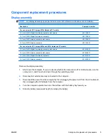
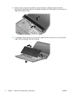
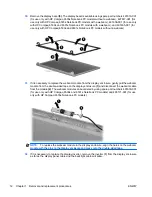

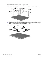


27.
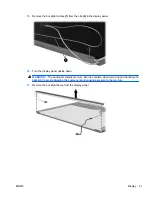
Remove the following:
CAUTION:
The display assembly will be unsupported when the following screws are removed.
To prevent damage to the display assembly, support it before removing the screws.
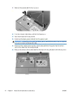
(1)
Four slotted Torx ST8M2.5×7.0 screws that secure the display assembly to the computer.
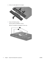
CAUTION:
There is a ground loop off the display panel cable
(2)
that is secured to the left hinge.
Be sure you do not pull or damage the cable.
(3)
Lift the display assembly straight up and remove it.
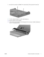
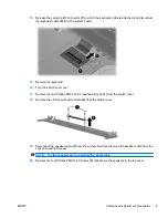
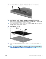
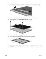
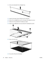
28.
If it is necessary to replace the display bezel, display inverter, or display hinges, remove the eight
rubber screw covers
(1)
and the eight Torx T8M2.5×6.0 screws
(2)
that secure the display bezel
to the display assembly. The rubber screw covers are available in the Rubber Kit, spare part
numbers 497622-001 (for use only with HP Compaq 6535s Notebook PC models) and 491654-001
(for use only with HP Compaq 6530s and 6531s Notebook PC models).
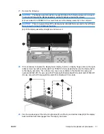
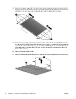
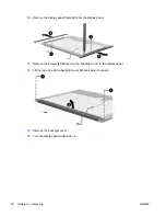
29.
Flex the inside edges of the left and right sides
(1)
and the top and bottom sides
(2)
of the display
bezel until the bezel disengages from the display enclosure.
ENWW
Component replacement procedures
11
Содержание Compaq 6530s
Страница 4: ...iv Safety warning notice ENWW ...
Страница 6: ...vi ENWW ...
Страница 7: ...1 Removal and replacement procedures ENWW 1 ...
Страница 22: ...16 Chapter 1 Removal and replacement procedures ENWW ...
Страница 30: ...24 Index ENWW ...
Страница 31: ......
Страница 32: ......


