background image

A–4

336492-003

Service Reference Guide, d300

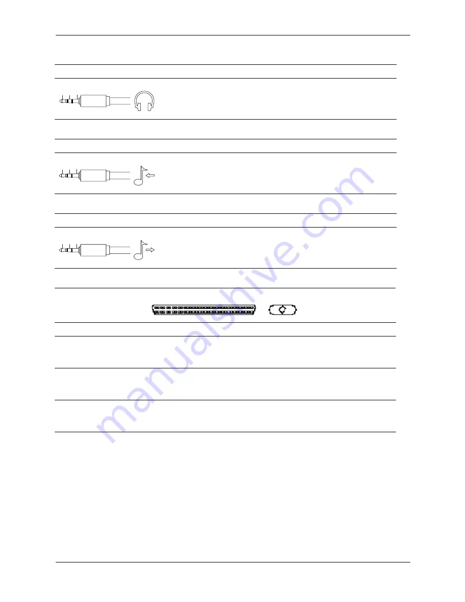
Connector Pin Assignments

Headphone

Connector and Icon (1/8” miniphone)

Pin

Signal

1 (Tip)

Audio_Left

2 (Ring)

Audio_Right

3 (Shield)

Ground

Line-In Audio

Connector and Icon (1/8” miniphone)

Pin

Signal

1 (Tip)

Audio_In_Left

2 (Ring)

Audio_In_Right

3 (Shield)

Ground

Line-Out Audio

Connector and Icon (1/8” miniphone)

Pin

Signal

1 (Tip)

Audio_Out_Left

2 (Ring)

Audio_Out_Right

3 (Shield)

Ground

SCSI Low Voltage Differential/Single Ended (LVD/SE)

Connector and Icon

Pin

Signal

Pin Signal

Pin

Signal

Pin

Signal

1-16


17-18


19

Ground


TERMPWR


Reserved

40


41


42

-D0


-D1


-D1

49-50


51-52


53

Ground


TERMPW


Reserved

60


61


62

-MSG


-SEL


-C/D

20-34


35


36

Ground


-D12


-D13

43


44


45

-D3


-D4


-D5

54


55


56

Ground


-ATN


Ground

63


64


65

-REQ


-I/O


-D

37


38


39

-D14


-D15


-DP1

46


47


48

-D6


-D7


-DP0

57


58


59

-BSY


-ACK


-RST

66


67


68

-D


-D


-D

1 2 3

1 2 3

1 2 3

Содержание Business Desktop d500 Series

Страница 1: ...es information on the removal and replacement of all parts as well as information on troubleshooting Desktop Management setup utilities SATA and PATA drives safety routine care connector pin assignments POST error messages and diagnostic indicator lights Document Part Number 336492 003 ...

Страница 2: ......

Страница 3: ...Service Reference Guide Business Desktop d500 Series 3rd Edition Document Part Number 336492 003 October 2003 ...

Страница 4: ... use of this material The information in this document is provided as is without warranty of any kind including but not limited to the implied warranties of merchantability and fitness for a particular purpose and is subject to change without notice The warranties for HP products are set forth in the express limited warranty statements accompanying such products Nothing herein should be construed ...

Страница 5: ...cs for Windows 2 13 2 3 3 Using Categories in Diagnostics for Windows 2 14 2 3 4 Running Diagnostic Tests in Diagnostics for Windows 2 16 2 4 Configuration Record 2 17 2 4 1 Installing Configuration Record 2 17 2 4 2 Running Configuration Record 2 17 2 5 Remote Diagnostics Enabling Agent 2 18 2 5 1 Installing or Upgrading Remote Diagnostics Enabling Agent 2 18 2 5 2 Running the Remote Diagnostics ...

Страница 6: ...urge Tolerant Power Supply 3 19 3 5 3 Thermal Sensor 3 19 4 Serial and Parallel ATA Drive Guidelines and Features 4 1 PATA and SATA Device Information 4 1 4 2 ATA Cables 4 1 4 2 1 SATA Data Cable 4 1 4 2 2 SATA Power Cable 4 2 4 2 3 PATA Data Cable 4 2 4 2 4 PATA Power Cable 4 2 4 2 5 PATA Cable Layout 4 3 4 3 PATA Drive Installation Guidelines 4 3 4 3 1 PATA Device Classes 4 4 4 3 2 PATA Attach S...

Страница 7: ...ry 5 8 6 Removal and Replacement Procedures Convertible Minitower CMT Chassis 6 1 Preparation for Disassembly 6 1 6 2 Unlocking the Smart Cover Lock 6 2 6 3 Hood Sensor 6 3 6 4 External Security Devices 6 4 6 4 1 Cable Lock 6 4 6 4 2 Padlock 6 5 6 5 Computer Access Panel 6 6 6 6 Front Bezel 6 7 6 7 Front Drive Bezels 6 8 6 7 1 5 25 Drive Bezel Blank 6 8 6 7 2 Diskette Drive Bezel or Bezel Blank 6 ...

Страница 8: ... Card Cage 7 11 7 9 1 Riser Card 7 12 7 9 2 Expansion Card 7 13 7 9 3 AGP Card 7 15 7 10Drives 7 17 7 10 1Drive Positions 7 17 7 10 2Cable Routing 7 18 7 10 3Optical Drive 7 19 7 10 4External 3 5 inch Drive 7 22 7 10 5Primary Hard Drive 7 25 7 11Front I O Devices 7 27 7 12Power Switch Assembly 7 28 7 13System Board 7 29 7 14Chassis Fan 7 30 7 15Battery 7 31 7 15 1Type 1 Battery Holder 7 32 7 15 2T...

Страница 9: ... 11Front I O Device 8 19 8 12Power Switch Assembly 8 20 8 13Processor and Heatsink 8 21 8 14Power Supply 8 22 8 15Battery 8 23 8 15 1Type 1 Battery Holder 8 24 8 15 2Type 2 Battery Holder 8 25 8 16Drive Cage Assembly 8 26 8 17Speaker 8 27 8 18Chassis Fan 8 28 8 19System Board 8 29 A Connector Pin Assignments B Power Cord Set Requirements C POST Error Messages D Troubleshooting Without Diagnostics ...

Страница 10: ...viii 336492 003 Service Reference Guide d500 Contents ...

Страница 11: ...een to complete the installation During this process do not turn off your computer unless you are directed to do so 1 0 1 Installing or Upgrading Device Drivers To install hardware devices such as a printer a display adapter or network adapter after the operating system installation is completed the operating system needs access to the appropriate software drivers for the devices The I386 director...

Страница 12: ...ofessional operating system is preinstalled on the computer and will be configured automatically the first time the computer is turned on The following HP software will also be installed at that time on selected models Computer Setup Utilities and diagnostic features HP Support Software including device drivers Configuration Record Online Safety Comfort Guide HP Intelligent Manageability Enhanced ...

Страница 13: ...sh and manage passwords and other security features Establish and manage energy saving timeouts All features identified in this chapter may not be available on all HP products 2 1 Power On Self Test POST POST is a series of diagnostic tests that runs automatically when the system is turned on POST checks the following items to ensure that the computer system is functioning properly Keyboard Memory...

Страница 14: ...suppresses most POST messages such as memory count product name and other non error text messages If a POST error occurs the error is displayed regardless of the mode selected To manually switch to POST Messages Enabled during POST press any key except F1 through F12 Establish an Ownership Tag the text of which is displayed each time the system is turned on or restarted Enter the Asset Tag or prop...

Страница 15: ...ist and press the Enter key 4 A choice of four headings appears in the Computer Setup Utilities menu File Storage Security and Advanced 5 Use the arrow left and right keys to select the appropriate heading Use the arrow up and down keys to select the option you want then press Enter To return to the Computer Setup Utilities menu press Esc 6 To apply and save changes select File Save Changes and Ex...

Страница 16: ...any established passwords Ignore Changes and Exit Exits Computer Setup without applying or saving any changes Save Changes and Exit Saves changes to system configuration and exits Computer Setup Storage Device Configuration Lists all installed non SCSI storage devices SCSI storage drives will not be listed in Computer F10 Setup When a device is selected detailed information and options are display...

Страница 17: ...Translation Parameters IDE disks only Allows you to specify the parameters logical cylinders heads and sectors per track used by the BIOS to translate disk I O requests from the operating system or an application into terms the hard drive can accept Logical cylinders may not exceed 1024 The number of heads may not exceed 256 The number of sectors per track may not exceed 63 These fields are only v...

Страница 18: ...ption Up to 4 PATA and 2 SATA devices may be accessed in this mode The SATA and PATA controllers appear as two separate IDE controllers Use this option with Win 2K and Win XP SATA 0 is seen as SATA Primary Device 0 SATA 1 if present is seen as SATA Secondary Device 0 Replace Primary IDE Controller is the other option Up to 2 PATA and 2 SATA devices may be accessed in this mode The SATA and PATA co...

Страница 19: ...er Setup options flash the ROM and make changes to certain plug and play settings under Windows See the Troubleshooting Guide for more information Power On Password Allows you to set and enable power on password See the Troubleshooting Guide for more information Password Options This selection will appear only if a power on password is set Allows you to specify whether the password is required for...

Страница 20: ...ust know the setup password if one is set Disable MBR Security before intentionally changing the formatting or partitioning of the current bootable disk Several disk utilities such as FDISK and FORMAT attempt to update the MBR If MBR Security is enabled and disk accesses are being serviced by the BIOS write requests to the MBR are rejected causing the utilities to report errors If MBR Security is ...

Страница 21: ...ilable on NIC models only the network controller must reside on the PCI bus or be embedded on the system board System IDs Allows you to set Asset tag 18 byte identifier and ownership Tag 80 byte identifier displayed during POST See Chapter 3 Desktop Management in this Guide Chassis serial number or Universal Unique Identifier UUID number The UUID can only be updated if the current chassis serial n...

Страница 22: ...his feature prevents the text from being displayed but pressing F10 will still access the Setup screen F12 prompt enable disable Enabling this feature will display the text F12 Network Service Boot during POST Disabling this feature prevents the text from being displayed but pressing F12 will still force the system to attempt booting from the network Option ROM prompt enable disable Enabling this ...

Страница 23: ...t work properly when USB buffers are at top of memory AND the system has 64 KB or less of RAM NIC Option ROM Download enable disable The BIOS contains an embedded NIC option ROM to allow the unit to boot through the network to a PXE server This is typically used to download a corporate image to a hard drive The NIC option ROM takes up memory space below 1MB commonly referred to as DOS Compatibilit...

Страница 24: ...I S3 options ACPI S3 Video REPOST AXPI S3 Hard disk Reset and ACPI S3 PS2 Mouse Wakeup will not be available ACPI S3 Video REPOST enable disable This feature reruns the video option ROM on a boot from the S3 state ACPI S3 Hard Disk Reset enable disable Resets the hard disk on a boot from the S3 sleep state ACPI S3 PS2 Mouse Wakeup enable disable Allows the mouse to wake the system from the S3 slee...

Страница 25: ...computer are recognized by the system and functioning properly Running tests is optional but recommended after installing or connecting a new device Third party devices not supported by HP may not be detected Save print or display the information generated by the utility 2 3 1 Detecting Diagnostics for Windows Some computers ship with the Diagnostics for Windows preloaded but not preinstalled To d...

Страница 26: ...dows To use categories 1 Click Start HP Information Center Diagnostics for Windows You can also select the Diagnostics for Windows icon located in the Control Panel The screen displays the overview of the computer hardware and software In Windows 2000 Professional select Start Settings Control Panel then select Diagnostics for Windows In Windows XP Home and Windows XP Professional select Start Con...

Страница 27: ...and Memory Map Health Status of system temperature and hard drives Miscellaneous CMOS DMI BIOS System Product Name and Serial Number Navigation Previous Category F5 Next Category F6 Level Less F7 More F8 information on the screen Tab Overview Displays general information about the computer This window is displayed when first starting the utility The left side of the window shows hardware informati...

Страница 28: ...to test a subsystem will be indicated by an error message under the subsystem name in the Test window or by shaded boxes that cannot be checked 4 Select Interactive Mode or Unattended Mode In Interactive Mode the diagnostic software will prompt you for input during tests that require it Some tests require interaction and will display errors or halt testing if selected in conjunction with Unattende...

Страница 29: ...zing the computer availability The information obtained by the utility is useful in troubleshooting system problems and streamlines the service process by enabling quick and easy identification of system configurations The utility displays it findings in a Now log file If the original Base log file is present in the cpqdiags directory the Base log file is displayed next to the Now log file in a sp...

Страница 30: ...e Diagnostics Enabling Agent only works if Diagnostics for Windows is also installed The Remote Diagnostics Enabling Agent is pre loaded on some computers and is available through a SoftPaq at http www hp com under Support and Drivers 2 5 1 Installing or Upgrading Remote Diagnostics Enabling Agent 1 Visit http www hp com support files and click on the applicable product 2 Locate the appropriate so...

Страница 31: ... 19 Setup Utilities and Diagnostics Features 2 7 Restoring the Software The Windows operating system and software can be restored to its original state by using the Restore CD See the Restore CD for complete instructions on using this feature ...

Страница 32: ...2 20 336492 003 Service Reference Guide d500 Setup Utilities and Diagnostics Features ...

Страница 33: ...f software unbundling process the computer is ready to be used A customized software image may be deployed by Installing additional software applications after unbundling the preinstalled software image Using software deployment tools such as Altiris Deployment Solutions to replace the preinstalled software with a customized software image Using a disk cloning process to copy the contents from one...

Страница 34: ...ng and Management HP provides several tools for managing and updating software on desktops and workstations Altiris PC Transplant Pro HP Client Manager Software an Altiris solution System Software Manager HP Proactive Notification and ActiveUpdate 3 3 1 HP Client Manager Software HP Client Manager Software HP CMS tightly integrates HP Intelligent Manageability technology within Altiris to provide ...

Страница 35: ... more information visit http www hp com go easydeploy 3 3 3 Altiris PC Transplant Pro Altiris PC Transplant Pro allows you to preserve old settings preferences and data and migrate them to the new environment quickly and easily For more information visit http www hp com go easydeploy 3 3 4 System Software Manager System Software Manager SSM lets you update system level software on multiple systems...

Страница 36: ...graded ROMPaq diskette from HP Download the latest ROMPaq images from http www hp com support ÄCAUTION For maximum ROM protection be sure to establish a setup password The setup password prevents unauthorized ROM upgrades System Software Manager allows the system administrator to set the setup password on one or more PCs simultaneously For more information visit http www hp com go ssml 3 3 8 Remot...

Страница 37: ...tup password has been established the Caps Lock light will turn on and you will be prompted to enter the password 6 Enter the setup password 7 If the system successfully starts from the diskette and successfully reprograms the ROM then the three keyboard lights will turn on A rising tone series of beeps also signals successful completion 8 Remove the diskette and turn the power off 9 Turn the powe...

Страница 38: ...n off power but instead causes the computer to enter a low power standby This allows you to quickly power down without closing applications and to quickly return to the same operational state without any data loss To change the power button s configuration complete the following steps 1 In Windows 2000 left click on the Start Button then select Settings Control Panel Power Options In Windows XP le...

Страница 39: ...for the monitor To access Display Properties right click on the Windows Desktop then choose Properties 3 3 13 World Wide Web Site When making the transition to new or revised operating systems it is important to implement the support software designed for that operating system If you plan to run a version of Microsoft Windows that is different from the version included with your computer you must ...

Страница 40: ...ettings on your HP computer Locally using the Computer Setup Utilities See the Computer Setup F10 Utility Guide included with the computer for additional information and instructions on using the Computer Setup Utilities Remotely using HP Client Manager or System Software Manager This software enables the secure consistent deployment and control of security settings from a simple command line util...

Страница 41: ... May prevent unintentional or malicious changes to the Master Boot Record of the current bootable disk and provides a means of recovering the last known good MBR From the Computer Setup Utilities F10 menu Memory Change Alerts Detects when memory modules have been added moved or removed notifies user and system administrator For information on enabling Memory Change Alerts refer to the online Intel...

Страница 42: ... in Windows click Start Shut Down Restart the Computer 2 Press the F10 key as soon as the monitor light turns green Press Enter to bypass the title screen if necessary If you do not press the F10 key at the appropriate time you must turn the computer off then on again and press the F10 key again to access the utility 3 Select Security then select Setup Password and follow the instructions on the s...

Страница 43: ...the following steps 1 Turn on or restart the computer If you are in Windows click Start Shut Down Restart the Computer 2 When the key icon appears on the monitor type your current password then press Enter Type carefully for security reasons the characters you type do not appear on the screen If you enter the password incorrectly a broken key icon appears Try again After three unsuccessful tries y...

Страница 44: ... the next time you turn on the computer Refer to the National Keyboard Delimiter Characters section in this chapter for information about the alternate delimiter characters The power on password and setup password may also be changed using the Security options in Computer Setup Deleting a Power On or Setup Password 1 Turn on or restart the computer If you are in Windows click Start Shut Down Resta...

Страница 45: ...mploys a two password security scheme One password is intended to be set and used by a system administrator while the other is typically set and used by the end user There is no back door that can be used to unlock the drive if both passwords are lost Therefore DriveLock is most safely used when the data contained on the hard drive is replicated on a corporate information system or is regularly ba...

Страница 46: ... things setting the DriveLock master password In the event that the user forgets the user password or the equipment is passed on to another employee the master password can always be used to reset the user password and regain access to the hard drive HP recommends that corporate system administrators who choose to enable DriveLock also establish a corporate policy for setting and maintaining maste...

Страница 47: ...efore exiting click File Save Changes and Exit Smart Cover Lock The Smart Cover Lock is a software controllable cover lock featured on select HP computers This lock prevents unauthorized access to the internal components Computers ship with the Smart Cover Lock in the unlocked position ÄCAUTION For maximum cover lock security be sure to establish a setup password The setup password prevents unauth...

Страница 48: ...key as soon as the monitor light turns green Press Enter to bypass the title screen if necessary If you do not press the F10 key at the appropriate time you must turn the computer off then on again and press the F10 key again to access the utility 3 Select Security Smart Cover Unlocked 4 Before exiting click File Save Changes and Exit Using the Smart Cover FailSafe Key If you enable the Smart Cove...

Страница 49: ... Save Changes and Exit When MBR Security is enabled the BIOS prevents any changes being made to the MBR of the current bootable disk while in MS DOS or Windows Safe Mode Most operating systems control access to the MBR of the current bootable disk the BIOS cannot prevent changes that may occur while the operating system is running Each time the computer is turned on or restarted the BIOS compares ...

Страница 50: ...lowing steps 1 Turn on or restart the computer If you are in Windows click Start Shut Down Restart the Computer 2 Press the F10 key as soon as the monitor light turns green Press Enter to bypass the title screen if necessary If you do not press the F10 key at the appropriate time you must turn the computer off then on again and press the F10 key again to access the utility 3 Select Security Master...

Страница 51: ...to help diagnose problems that might result in unwarranted hard drive replacement When HP computers are built each installed hard drive is tested using DPS and a permanent record of key information is written onto the drive Each time DPS is run test results are written to the hard drive Your service provider can use this information to help diagnose conditions that caused you to run the DPS softwa...

Страница 52: ...3 20 336492 003 Service Reference Guide d500 Desktop Management ...

Страница 53: ... data cable 40 80 7 7 Number of pins in power cable 4 15 Maximum data cable length 18 in 45 7 cm 39 37 in 100 cm Data interface voltage differential 5 V 600 mV Drive motor voltages 5 V 12 V 3 3 V 12 V Jumpers for configuring drive Required N A Data transfer rate up to 100 MB s 150 MB s Pin Number Usage Device Plug Host Plug P1 Ground Ground Ground P2 A Transmit data Receive data P3 A Transmit data...

Страница 54: ...d P5 Ground P13 V 12 12 V power P6 Ground P14 V12 12 V power P7 V5 5 V power P15 V12 12 V power P8 V5 5 V power Pin Signal Pin Signal Pin Signal 1 2 3 4 5 Reset Ground DD7 DD8 DD6 15 16 17 18 19 DD1 DD14 DD0 DD15 Ground 29 30 31 32 33 DMAK Ground INTRQ IOCS16 DA1 6 7 8 9 10 DD9 DD5 DD10 DD4 DD11 20 21 22 23 24 Key DMARQ Ground DIOW Ground 34 35 36 37 38 PDIAG cable detect DA0 DA2 CS1FX CS3FX 11 12...

Страница 55: ...he system board connector Some cables may be labeled Drive 0 instead of Device 0 and Drive 1 instead of Device 1 4 3 PATA Drive Installation Guidelines Most computer system boards have two ATA IDE channels with a dedicated connector for each channel One channel is designated as the primary and the other as the secondary channel Each of the two channels can have up to two devices attached to it Eac...

Страница 56: ...termined by the device class of the drives and by specific attach sequence rules 4 3 1 PATA Device Classes In order to determine the best drive attach sequence ATA ATAPI drives are segregated into four different classes based upon the bandwidth demands they place on an ATA channel The most demanding devices are in Class 1 and the least demanding are in Class 4 General Attach Guidelines The lower t...

Страница 57: ...ives and removable media drives on separate channels to maximize compatibility Keeping the hard drive and the writable optical drive on separate channels to maximize optical drive reliability General Attach Sequence Rule Sequence Description 1 The lowest class drive bootable hard drive recommended 2 If only two drives the last drive goes here otherwise the lowest class of the remaining drives 3 If...

Страница 58: ...r obtaining optimum system performance when setting up a computer with multiple drives Use the General Attach Sequence Rule to determine the best drive installation sequence Two examples of how to use the worksheet are Three device installation Four device installation Attach Sequence Worksheet Device Name Device Class Position Number Channel Name Device Number ...

Страница 59: ...e in Section 4 3 1 the devices may be identified as Ultra ATA 100 hard drive Class 1 DVD drive Class 2 CD ROM drive Class 3 Cable lengths may restrict drive usage Attach Sequence Worksheet Three Device Installation Sample Device Name Device Class Position Number Channel Name Device Number Ultra ATA 100 hard drive 1 1 Primary 0 DVD drive 2 2 Secondary 0 CD ROM drive 3 3 Secondary 1 1 2 4 3 Primary ...

Страница 60: ...wing the General Attach Sequence Rule Cable lengths may restrict drive usage 4 3 4 PATA Additional Drive Application Notes When replacing a hard drive the replacement should be of the same type Ultra ATA 33 66 or 100 as that being removed to retain the same level of performance When Ultra ATA and SCSI hard drives are mixed in the same system the Ultra ATA drive will become the boot drive unless th...

Страница 61: ...sed by the operating system A single hard drive may therefore be subdivided into a number of unique drive partitions in order to make use of all of its space Because of the differences in the way that drive sizes are calculated the size reported by the operating system may differ from that marked on the hard drive or listed in the computer specification Drive size calculations by drive manufacture...

Страница 62: ...annel Command block 170h 177h Control block 376h IRQ 15 4 6 2 Native Mode The native mode is used to access devices attached to add in cards and is not supported by many legacy operating systems Addresses are assigned by PCI Plug n Play BIOS and the IRQ is shared with multiple controllers Base Address Registers for the Command and Control Block are found in the PCI Configuration Space Offset 10h P...

Страница 63: ...1 SATA 0 B2 SATA 1 Add as a separate channel Used with Windows 2000 and XP A Integrated SATA B Integrated IDE A1 SATA 0 A2 SATA 1 B1 IDE Primary Device 0 B2 IDE Primary Device 1 B3 IDE Secondary Device 0 B4 IDE Secondary Device 1 Replace primary IDE channel Used with Windows 9x NT and Linux A Integrated IDE B Integrated SATA A1 IDE Secondary Device 0 A2 IDE Secondary Device 1 B1 SATA 0 B2 SATA 1 R...

Страница 64: ...4 12 336492 003 Service Reference Guide d500 Serial and Parallel ATA Drive Guidelines and Features ...

Страница 65: ...e to the procedures and precautions described in this chapter is essential for proper service Ä CAUTION When the computer is plugged into an AC power source voltage is always applied to the system board You must disconnect the power cord from the power source before opening the computer to prevent system board or component damage 5 1 Chassis Designations 5 1 1 Convertible Minitower CMT ...

Страница 66: ...5 2 336492 003 Service Reference Guide d500 Identifying the Chassis Routine Care and Disassembly Preparation 5 1 2 Small Form Factor SFF 5 1 3 Ultra Slim Desktop USDT ...

Страница 67: ...rcuitry design and structure determine the degree of sensitivity The following packaging and grounding precautions are necessary to prevent damage to electric components and accessories To avoid hand contact transport products in static safe containers such as tubes bags or boxes Protect all electrostatic parts and assemblies with conductive or approved containers or packaging Keep electrostatic s...

Страница 68: ...urface and properly grounded tools and equipment Use static dissipative mats foot straps or air ionizers to give added protection Handle electrostatic sensitive components parts and assemblies by the case or PCB laminate Handle them only at static free work areas Turn off power and input signals before inserting and removing connectors or test equipment Use fixtures made of static safe materials w...

Страница 69: ... 4 Always unplug the computer before cleaning the keyboard mouse or air vents 5 Disconnect the keyboard before cleaning it 6 Wear safety glasses equipped with side shields when cleaning the keyboard 5 3 2 Cleaning the Computer Case Follow all safety precautions in Section 5 3 1 before cleaning the computer To clean the computer case follow the procedures described below To remove light stains or d...

Страница 70: ...emove a wide leveled key like the space bar from the keyboard If these keys are improperly removed or installed the keyboard may not function properly Cleaning under a key may be done with a swab moistened with isopropyl alcohol and squeezed out Be careful not to wipe away lubricants necessary for proper key functions Use tweezers to remove any fibers or dirt in confined areas Allow the parts to a...

Страница 71: ...d the following Torx T 15 screwdriver Compaq screwdriver with bits PN 161946 001 Torx T 15 screwdriver with small diameter shank for certain front bezel removal Flat bladed screwdriver may sometimes be used in place of the Torx screwdriver Phillips 2 screwdriver Diagnostics software Compaq tamper resistant T 15 wrench Smart Cover FailSafe Key PN 166527 001 or Compaq tamper resistant bits Smart Cov...

Страница 72: ...r protective packaging until they are actually mounted in the CPU Avoid dropping drives from any height onto any surface If you are inserting or removing a hard drive turn off the computer Do not remove a hard drive while the computer is on or in standby mode Before handling a drive ensure that you are discharged of static electricity While handling a drive avoid touching the connector For more in...

Страница 73: ...ultiBay device from the computer 5 Turn off the computer and any peripheral devices that are connected to it Ä CAUTION Turn off the computer before disconnecting any cables Ä CAUTION Regardless of the power on state voltage is always present on the system board as long as the system is plugged into an active AC outlet In some systems the cooling fan is on even when the computer is in the Standby o...

Страница 74: ...need to remove the locking solenoid by using the Smart Cover FailSafe Key Spare part number 166527 001 or 166527 002 Once the solenoid has been deactivated or removed the access panel can be removed The Smart Cover FailSafe Key will be needed in any of the following circumstances Power outage Startup failure Processor or power supply failure Lost password 1 Using the Smart Cover FailSafe Key remov...

Страница 75: ...Hood Sensor 1 Prepare the computer for disassembly Section 6 1 2 Remove the access panel Section 6 5 3 Disconnect the hood sensor cable from the system board 4 Slide the hood sensor switch towards the front of the computer 1 and lower it down through the slot 2 To install the hood sensor reverse the removal procedure ...

Страница 76: ...oval and Replacement Procedures Convertible Minitower CMT Chassis 6 4 External Security Devices 6 4 1 Cable Lock The cable lock may be used to secure the computer access panel to the chassis and at the same time secure the computer to a fixed object ...

Страница 77: ...l and Replacement Procedures Convertible Minitower CMT Chassis 6 4 2 Padlock A padlock may be used by itself to secure the access panel to the computer chassis A padlock may also be used with a security cable to secure the computer to a fixed object I ...

Страница 78: ...r for disassembly Section 6 1 ÄCAUTION Before removing the computer access panel ensure that the computer is turned off and that the power cord is disconnected from the electrical outlet 2 Lift up on the access panel handle 1 slide the access panel back about 1 inch 2 5 cm then lift it off the unit 2 To install the computer cover reverse the removal procedure ...

Страница 79: ...nitower CMT Chassis 6 6 Front Bezel 1 Prepare the computer for disassembly Section 6 1 2 Remove the computer access panel Section 6 5 3 Push up on the two release tabs 1 then rotate the front bezel away from the chassis to release it 2 To reinstall the front bezel reverse the removal procedure ...

Страница 80: ...el blanks secured in it away from the front bezel then remove the desired bezel blank ÄCAUTION Hold the subpanel straight when pulling it away from the front bezel Pulling the subpanel away at an angle could damage the pins that align it with the front bezel To install a bezel blank reverse the removal procedure When replacing the subpanel ensure that the aligning pins and any remaining bezel blan...

Страница 81: ...hassis 6 7 2 Diskette Drive Bezel or Bezel Blank Press up on the two small retaining clips 1 on the bottom of the bezel insert press down on the two small retaining clips 2 on the top of the insert and push the cover out of the front bezel 3 To install a bezel or a bezel blank reverse the removal procedure ...

Страница 82: ...cts Doing so may damage the module 1 If you have locked the Smart Cover Lock use Computer Setup to unlock the lock Section 6 2 2 Prepare the computer for disassembly Section 6 1 3 Remove the computer access panel Section 6 5 ÅWARNING To reduce risk of personal injury from hot surfaces allow the internal system components to cool before touching 4 Open both latches of the memory module socket 1 and...

Страница 83: ...ible Minitower CMT Chassis The computer automatically recognizes the additional memory when the computer is turned on To reassemble the computer reverse the removal procedure If you normally lock the Smart Cover Lock use Computer Setup to relock the lock and enable the Smart Cover Sensor ...

Страница 84: ...e computer access panel Section 6 5 4 Locate the correct vacant expansion socket on the system board and the corresponding expansion slot on the back of the computer chassis 5 Push down and out on the two green thumb tabs inside the chassis and rotate the expansion card retention latch up 6 If you are installing an expansion card in a vacant socket remove the appropriate expansion slot cover on th...

Страница 85: ...ard expansion socket hold the card at each end and carefully rock it back and forth until the connectors pull free from the socket Lift the expansion card straight up to release it from the chassis frame Be sure not to scrape the card against other components Before removing an installed expansion card disconnect any cables that may be attached to the expansion card ...

Страница 86: ... toward the center of the chassis to release it from the chassis frame Be sure not to scrape the card against other components 9 Store the removed card in anti static packaging 10 If you are not installing a new expansion card install an expansion slot cover to close the open slot and continue with step 12 If you are installing a new expansion card continue with step 11 ÄCAUTION After removing an ...

Страница 87: ...ole connector seats properly in the expansion card socket on the system board 12 Close the expansion slot latch making sure that it snaps firmly into place 13 Connect external cables to the installed card and internal cables to the system board as needed 14 Replace the computer access panel 15 If you normally lock the Smart Cover Lock use Computer Setup to relock the lock and enable the Smart Cove...

Страница 88: ...ly Section 6 1 2 Remove the computer access panel Section 6 5 3 Locate the correct vacant expansion socket on the system board and the corresponding expansion slot on the back of the computer chassis 4 Push down and out on the two green thumb tabs inside the chassis and rotate the expansion card retention latch up 5 Use a thin flat blade screwdriver to pry up on the broken plastic latches 1 then c...

Страница 89: ...1 then lift the left end 2 to remove it from the chassis To replace the bar slide it into the socket on the right 1 lower it into position 3 and slide it to the left 4 to secure it in place 7 With the bar in a slightly rotated position install the latches through the openings in the back of the chassis and press them firmly in place on the rotating bar ...

Страница 90: ...1 Drive Positions To verify the type and size of the storage device installed in the computer run Computer Setup Drive Positions Item Description Item Description 1 Three 5 25 inch half height bays for optional drive 3 Two internal 3 5 inch one third height bay for hard drives 2 One standard 3 5 inch one third height bay 1 44 MB diskette drive shown The bottom 5 25 inch drive bay has a shorter dep...

Страница 91: ...While handling a drive avoid touching the connector For more information about preventing electrostatic damage refer to Chapter 5 for more information Handle a drive carefully do not drop it Do not use excessive force when inserting a drive Avoid exposing a hard drive to liquids temperature extremes or products that have magnetic fields such as monitors or speakers 1 If you have locked the Smart C...

Страница 92: ... 1 for that drive and slide the drive from the drive bay 2 7 Remove the four guide screws two on each side from the old drive and install them in the replacement drive Extra guide screws are provided on the chassis on the side of the fourth drive bay Optical drives use M3 metric screws The HP supplied metric screws are black The HP supplied standard screws are silver ...

Страница 93: ...eplacement Procedures Convertible Minitower CMT Chassis 8 Store the removed drive in anti static packaging 9 Install the new drive by sliding it into the appropriate drive bay on the front of the chassis The drivelock automatically secures the drive in the bay ...

Страница 94: ... 5 4 Remove the front bezel Section 6 6 If you are adding a drive in a bay that was previously empty you must remove the corresponding bezel blank from the front bezel 5 Disconnect the audio power and data cables on the back of the drive Install four guide screws in the lower holes on each side of the drive ÄCAUTION When removing cables pull the tab or connector instead of the cable itself to prev...

Страница 95: ...t specific drive and slide the drive from the drive bay 2 9 Remove the four guide screws two on each side from the old drive and install them in the lower set of holes on the optical drive Extra guide screws are provided on the chassis on the side of the fourth drive bay Optical drives use M3 metric screws The HP supplied metric screws are black The HP supplied standard screws are silver ...

Страница 96: ...n damage to the drive 11 When installing an optical drive the default audio solution is digital audio If analog audio is preferred connect the audio cable from the drive to the embedded audio connector on the system board 12 Connect the data and power cables on the to the drive Refer to Chapter 4 Serial and Parallel ATA Drive Guidelines and Features for information on attaching the cabling to get ...

Страница 97: ...n each side of the drive Extra guide screws are provided on the side of the drive bay under the access panel The diskette drive use M3 metric screws The HP supplied metric screws are black The HP supplied standard screws are silver 7 Insert the diskette drive into the bay from the front of the chassis Push it in until it locks into place ÄCAUTION Make sure the guide screws line up with the guide s...

Страница 98: ... off the chassis 3 7 Carefully pull the cables from the front of the chassis making sure that they do not snag on the lower drive cage To reinstall the I O device 1 Thread the cables through the opening and down the space in front of the lower drive cage This step may be easier if you thread a single cable at a time through the opening ÄCAUTION Be careful when threading the cables in the chassis s...

Страница 99: ...ction 6 5 3 Disconnect the power switch LED cable from the system board 4 Squeeze the switch holder retaining clips together at the front of the chassis 1 and push the switch assembly out of the chassis 2 To install the power switch assembly reverse the removal procedure When installing the power switch cable it may be necessary to disconnect a data cabe from one of the drives to make it easier to...

Страница 100: ...s Section 6 9 4 Remove the AGP graphics card Section 6 9 5 Disconnect all cables connected to the system board noting their location for reinstallation 6 Compress the system board tray handle 1 to release the latch and slide the system board tray towards the front of the computer 2 to free it from the back of the chassis To install the system board with its tray press down on the board to ensure i...

Страница 101: ...ery only with the HP Compaq spare designated for this product Ä CAUTION Before replacing the battery it is important to back up the computer CMOS settings When the battery is removed or replaced the CMOS settings will be cleared Refer to the Troubleshooting Guide for information on backing up the CMOS settings N Batteries battery packs and accumulators should not be disposed of together with the g...

Страница 102: ... 2 Slide the replacement battery into position positive side up 3 The battery holder automatically secures the battery in the proper position 4 Replace the computer cover or access panel 5 Plug in the computer and turn on power to the computer 6 Reset the date and time your passwords and any special system setups using Computer Setup Refer to the Computer Setup F10 Utility Guide ...

Страница 103: ...ft it out 2 To insert the new battery slide one edge of the replacement battery under the holder s lip with the positive side up 2 Push the other edge down until the clamp snaps over the other edge of the battery After the battery has been replaced use the following steps to complete this procedure 3 Replace the computer access panel 4 Plug in the computer and turn on power to the computer Reset t...

Страница 104: ... 6 16 1 Type 1 1 Release the tension from the heatsink 1 and 2 2 Remove the retaining clips 3 3 Remove the heatsink from atop the processor 4 4 Open the ZIF socket lever 5 5 Remove the processor 6 To install the processor and heatsink 1 Insert the processor into the ZIF socket 2 Press down on the processor while rotating and locking the ZIF socket handle in place 3 Refresh the thermal grease betwe...

Страница 105: ... 4 Open the ZIF socket lever 5 5 Remove the processor 6 To install the processor and heatsink 1 Insert the processor into the ZIF socket 2 Press down on the processor while rotating and locking the ZIF socket handle in place 3 Refresh the thermal grease between the heatisnk and processor if necessary 4 Install the heatsink and latch it in place 5 Connect the heatsink fan control to the system boar...

Страница 106: ...Open the ZIF socket lever 4 5 Remove the processor 5 To install the processor and heatsink 1 Insert the processor into the ZIF socket 2 Press down on the processor while rotating and locking the ZIF socket handle in place 3 Refresh the thermal grease between the heatisnk and processor if necessary 4 Install the heatsink and latch it in place 5 Connect the heatsink fan control to the system board 6...

Страница 107: ...er 1 Prepare the computer for disassembly Section 6 1 2 Remove the computer access panel Section 6 5 3 Disconnect the speaker wire from the system board 4 Remove the four screws from the inside of the chassis 1 that secure the speaker to the chassis 5 Remove the speaker 2 To install the speaker reverse the removal procedures ...

Страница 108: ...is Fan 1 Prepare the computer for disassembly Section 6 1 2 Remove the computer access panel Section 6 5 3 Disconnect the fan control cable from the system board 4 Remove the four screws that secure the fan assembly to the chassis 1 and then remove the fan assembly 2 To install the fan assembly reverse the removal procedure ...

Страница 109: ... power cord should be disconnected from the computer and or the AC outlet before opening the computer 1 Prepare the computer for disassembly Section 6 1 1 Remove the computer access panel Section 6 5 2 Disconnect all power cables from the mass storage devices and from the system board 3 Remove the four screws that connect the power supply to the chassis 1 4 Slide the power supply toward the front ...

Страница 110: ...up to unlock it 2 Prepare the computer for disassembly Section 6 1 3 Remove the computer access panel Section 6 5 4 Remove the front bezel Section 6 6 5 Disconnect all power and data cables from the back of the drives in the 5 25 inch drive bays 6 To release the drives from the 5 25 inch drive bay press down on the short yellow drivelock as shown While pressing the drivelock pull the drives out of...

Страница 111: ...supports a drive that is no more than 6 7 inches in depth including the cables that attach to the back of the drive Do not try to force a larger drive such as an optical drive or MultiBay drive into the bottom bay This could cause damage to the drive and the system board The use of unnecessary force when installing any drive into the drive bay may result in damage to the drive 9 Reconnect all powe...

Страница 112: ...6492 003 Service Reference Guide d500 Removal and Replacement Procedures Convertible Minitower CMT Chassis 12 Reposition the subpanel rotate it 180 with the logo at the bottom then snap it back into the bezel ...

Страница 113: ...computer for disassembly Section 6 1 3 Remove the computer access panel Section 6 5 4 Remove the front bezel Section 6 6 5 Disconnect all power and data cables from the back of the drives in the 5 25 inch drive bays 6 To release the drives from the 5 25 inch drive bay lift the release tab on the green latch drive bracket for the drive While lifting the release tab slide the drive from its drive ba...

Страница 114: ...orts a drive that is no more than 6 7 inches in depth including the cables that attach to the back of the drive Do not try to force a larger drive such as an optical drive or MultiBay drive into the bottom bay This could cause damage to the drive and the system board The use of unnecessary force when installing any drive into the drive bay may result in damage to the drive 9 Reconnect all power an...

Страница 115: ...sis 12 Reposition the subpanel rotate it 180 with the logo at the bottom then snap it back into the bezel 13 Replace the front bezel and computer access panel 14 Reconnect the external equipment 15 If you normally lock the Smart Cover Lock use Computer Setup to relock the lock and enable the Smart Cover Sensor ...

Страница 116: ...6 44 336492 003 Service Reference Guide d500 Removal and Replacement Procedures Convertible Minitower CMT Chassis ...

Страница 117: ...ve any diskette compact disc or MultiBay device from the computer 5 Turn off the computer and any peripheral devices that are connected to it Ä CAUTION Turn off the computer before disconnecting any cables Ä CAUTION Regardless of the power on state voltage is always present on the system board as long as the system is plugged into an active AC outlet In some systems the cooling fan is on even when...

Страница 118: ...Spare part number 166527 001 or 166527 002 Once the solenoid has been deactivated or removed the access panel can be removed The Smart Cover FailSafe Key will be needed in any of the following circumstances Power outage Startup failure Processor or power supply failure Lost password 1 Using the Smart Cover FailSafe Key remove the two tamper proof screws that secure the Smart Cover Lock to the insi...

Страница 119: ...er for disassembly Section 7 1 2 Remove the computer access panel Section 7 5 3 Remove the front bezel Section 7 6 4 Raise the drive cage to its upright position 1 5 Slide the hood sensor switch towards the inside of the computer 2 6 Disconnect the hood sensor cable from the system board 3 To install the hood sensor reverse the removal procedure ...

Страница 120: ...le lock may be used to secure the computer access panel to the chassis and at the same time secure the computer to a fixed object As shown there are two acceptable methods for using the cable lock While both methods work for added security HP recommends that you use the method shown on the left where the cable lock penetrates both the access panel and the chassis ...

Страница 121: ...val and Replacement Procedures Small Form Factor SFF Chassis 7 4 2 Padlock A padlock may be used by itself to secure the access panel to the computer chassis A padlock may also be used with a security cable to secure the computer to a fixed object I ...

Страница 122: ...y Section 7 1 ÄCAUTION Before removing the computer access panel ensure that the computer is turned off and that the power cord is disconnected from the electrical outlet 2 Pull up and hold open the latch on the top of the computer 1 3 Slide the computer cover 2 back about 0 5inch 1 3 cm then lift it off the unit To install the computer cover reverse the removal procedure ...

Страница 123: ... SFF Chassis 7 6 Front Bezel 1 Prepare the computer for disassembly Section 7 1 2 Remove the computer access panel Section 7 5 3 Pull up on the three release tabs 1 on the top of the bezel then pull the front bezel away from the chassis 2 To reinstall the front bezel reverse the removal procedure ...

Страница 124: ...puter for disassembly Section 7 1 2 Remove the computer access panel Section 7 5 3 Remove the front bezel Section 7 6 7 7 1 Diskette Drive Bezel or Bezel Blank Press the large retaining tab 1 on the left side of the bezel insert to the left and push the cover out of the front bezel 2 To install a bezel or a bezel blank reverse the removal procedure ...

Страница 125: ...s Doing so may damage the module 1 If you have locked the Smart Cover Lock use Computer Setup to unlock the lock Section 7 2 2 Prepare the computer for disassembly Section 7 1 3 Remove the computer access panel Section 7 5 ÅWARNING To reduce risk of personal injury from hot surfaces allow the internal system components to cool before touching 4 Open both latches of the memory module socket 1 and i...

Страница 126: ... Form Factor SFF Chassis The computer automatically recognizes the additional memory when the computer is turned on To reassemble the computer reverse the removal procedure If you normally lock the Smart Cover Lock use Computer Setup to relock the lock and enable the Smart Cover Sensor ...

Страница 127: ...r Setup to unlock the lock Section 7 2 2 Prepare the computer for disassembly Section 7 1 3 Remove the computer access panel Section 7 5 4 Disconnect all cables attached to the expansion cards 5 Grasp the expansion card cage by the green labels the cage in the computer has two spots marked 1 and pull it straight up from the chassis To install the card cage reverse the removal procedures ...

Страница 128: ...Cover Lock use Computer Setup to unlock the lock Section 7 2 2 Prepare the computer for disassembly Section 7 1 3 Remove the computer access panel Section 7 5 4 Remove the expansion card cage Section 7 9 5 Remove the three screws that secure the riser card to the expansion card cage then remove the card To install the riser card reverse the removal procedure ...

Страница 129: ...cess panel Section 7 5 4 Remove the expansion card cage Section 7 9 5 If you are installing a card for the first time go to step 6 If you are removing an existing card open the release latch as described in step 6 then go to step 8 6 If you are installing an expansion card in a vacant socket release the slot cover retention latch 1 that secures the PCI slot covers by rotating the latch outwards th...

Страница 130: ... Form Factor SFF Chassis 8 To remove an expansion card hold the card at each end and carefully rock it back and forth until the connectors pull free from the socket Lift the expansion card straight up to release it from the carrier Be sure not to scrape the card against other components ...

Страница 131: ... sure you press firmly on the card so that the whole connector seats properly in the expansion card socket on the system board 8 Close the expansion slot retention bracket by rotating it toward the chassis 1 and pressing down on the thumb tabs 2 so that they snap firmly into place 9 To remove an AGP card pull the retention arm away from the socket then carefully rock the card back and forth until ...

Страница 132: ... and internal cables to the system board as needed 12 Replace the computer cover 13 If you normally lock the Smart Cover Lock use Computer Setup to relock the lock and enable the Smart Cover Sensor 14 Reconfigure the computer if necessary Refer to the Computer Setup F10 Utility Guide on the Documentation Library CD for instructions about using Computer Setup ...

Страница 133: ... type and size of the storage device installed in the computer run Computer Setup Drive Positions Item Description Item Description 1 One standard 3 5 inch one third height bay 1 44 MB diskette drive shown 3 Internal 3 5 inch one third height bay for hard drive 2 5 25 inch drive bay for optional drives If the computer has a 1 44 MB diskette drive installed it will be configured with a diskette dri...

Страница 134: ...o the floor of the chassis Keep the cable clear of the power supply fan 3 Fold the diskette drive flat ribbon data cable 3 near the connector on the drive Route the cable up high on the drive cage near the cable connectors then folding again to lay beneath the optical drive data cable Be sure the diskette drive cable does not rest on the power supply and does not interfere with the power supply fa...

Страница 135: ...on 7 6 5 Raise the Easy Access drive bay to the upright position 6 Disconnect the audio signal and drive power cables from the drive The other end of the cables should remain connected to the system board 7 Make sure the drive cables are routed properly Section 7 10 2 8 Return the Easy Access drive bay to the down position 9 Push the drive release latch 1 toward the rear of the chassis and hold 10...

Страница 136: ...ing the drive transfer the four screws from the old drive to the new one The screws take the place of drive rails 2 Position the guide screws on the drive into the J slots in the drive bay 1 Then slide the drive towards the rear of the computer 2 The drive release latch automatically locks in place when installing a drive ...

Страница 137: ...ptical drive 5 Make sure the drive cables are routed properly Section 7 10 2 6 Return the Easy Access drive bay to the down position Be sure not to pinch the cables in the chassis when lowering the Easy Access drive bay 7 Replace the front bezel and computer access panel The system automatically recognizes the drive and reconfigures the computer ÄCAUTION When servicing the computer ensure that cab...

Страница 138: ...ss drive bay to the upright position 6 Disconnect the audio signal and drive power cables from the drive The other end of the cables should remain connected to the system board 7 Make sure the drive cables are routed properly Section 7 10 2 8 Return the Easy Access drive bay to the down position 9 Push the drive release latch 1 toward the rear of the chassis and hold 10 Slide the drive 2 toward th...

Страница 139: ... the back of the drive cage until the front screws are aligned with the front J slots Then lower the front of the drive Continue to slide the drive all the way back until it locks into place If replacing a diskette drive all guide screws front and rear will line up on the J slots Insert the guide screws into the J slots then slide the drive toward the back of the drive cage until it locks into pla...

Страница 140: ...de d500 Removal and Replacement Procedures Small Form Factor SFF Chassis 14 If the drive cage was raised to gain access to the drive cables lower it to its original position at this time 15 Replace the front bezel and computer access panel ...

Страница 141: ... Cover Lock use Computer Setup to unlock the lock Section 7 2 2 Prepare the computer for disassembly Section 7 1 3 Remove the computer access panel Section 7 5 4 Remove the front bezel Section 7 6 5 Raise the Easy Access drive bay to the upright position 6 Disconnect the power cable and signal cable from the back of the drive Disconnecting Cables from the Hard Drive ...

Страница 142: ...ll the drive from the bay 3 To replace the hard drive reverse the above procedure Make sure you position all cable correctly before returning the drive cage to its original position Section 7 10 2 When replacing the hard drive transfer the four screws from the old drive to the new one The screws take the place of drive rails You will need a Torx T 15 screwdriver to remove and re install the guide ...

Страница 143: ... panel Section 7 5 3 Disconnect the two I O device cables from the system board the front USB cable pair and the front audio cable 4 Remove the power supply from the chassis Section 7 18 5 From the inside of the chassis remove the two screws that secure the I O device to the chassis 1 then pull the device into the chassis 2 to free it from its mount To install the housing assembly reverse the remo...

Страница 144: ... 3 Disconnect the power switch LED cable from the system board 4 Carefully cut the cable tie that secures the power switch cable to the power supply cable cable bundle ÄCAUTION Be careful when cutting the cable tie not to cut any cables 5 Squeeze the switch holder retaining clips together at the front of the chassis 1 and push the switch assembly out of the chassis 2 To install the power switch as...

Страница 145: ... AGP graphics card Section 7 9 5 Disconnect all cables connected to the system board noting their location for reinstallation 6 Compress the system board tray handle 1 to release the latch and slide the system board tray towards the front of the computer 2 to free it from the back of the chassis To install the system board with its tray slide the tray assembly into the chassis and press down on th...

Страница 146: ...the wiring harness and from cable clip 1 near the front of the chassis 5 Remove the two screws that secure the fan to the chassis 2 then slide the fan up and out of the chassis 3 To install the chassis fan reverse the removal procedure After installing the screws spin the fan blades to ensure they are not making contact with the fan housing ÄCAUTION Do not overtighten the two mounting screws Overt...

Страница 147: ...ignated for this product Ä CAUTION Before replacing the battery it is important to back up the computer CMOS settings When the battery is removed or replaced the CMOS settings will be cleared Refer to the Troubleshooting Guide for information on backing up the CMOS settings N Batteries battery packs and accumulators should not be disposed of together with the general household waste In order to fo...

Страница 148: ... Slide the replacement battery into position positive side up 3 The battery holder automatically secures the battery in the proper position 4 Replace the computer cover or access panel 5 Plug in the computer and turn on power to the computer 6 Reset the date and time your passwords and any special system setups using Computer Setup Refer to the Computer Setup F10 Utility Guide ...

Страница 149: ...battery slide one edge of the replacement battery under the holder s lip with the positive side up 2 Push the other edge down until the clamp snaps over the other edge of the battery After the battery has been replaced use the following steps to complete this procedure 3 Replace the computer cover or access panel 4 Plug in the computer and turn on power to the computer Reset the date and time your...

Страница 150: ...e If it is cool enough to handle then proceed 6 Twist the heatsink slightly to break the bond between it and the processor the lift the heatsink from the processor 5 7 Rotate the ZIF socket handle to its fully open position 6 and remove the processor from the socket 7 To install the processor and heatsink 1 Insert the processor into the ZIF socket 2 Press down on the processor while rotating and l...

Страница 151: ...sion card cage Section 7 9 5 Disconnect the speaker wire from the system board 6 Carefully cut the cable tie that secures the speaker cable to the power supply cable bundle ÄCAUTION Be careful when cutting the cable tie not to cut any cables 7 Remove the power supply from the chassis Section 7 18 8 Remove the two screws that secure the speaker to the chassis 9 Slide the speaker towards the rear of...

Страница 152: ...ction 7 1 2 Remove the computer access panel Section 7 5 3 Rotate the drive cage to its upright position 4 Remove the expansion card cage Section 7 9 5 Carefully cut the cable tie that secures the power supply cable bundle to the power switch cable the speaker cable and the front I O cable 6 Disconnect all power cables from the mass storage devices and from the system board 7 Remove the three scre...

Страница 153: ...y diskette compact disc or MultiBay device from the computer 5 Turn off the computer and any peripheral devices that are connected to it Ä CAUTION Turn off the computer before disconnecting any cables Ä CAUTION Regardless of the power on state voltage is always present on the system board as long as the system is plugged into an active AC outlet In some systems the cooling fan is on even when the ...

Страница 154: ...492 003 Service Reference Guide Removal and Replacement Procedures Ultra Slim Desktop USDT Chassis 8 If the PC is mounted in the accessory mounting stand remove it and lay the computer down on its rubber feet ...

Страница 155: ... Replacement Procedures Ultra Slim Desktop USDT Chassis 8 2 External Security Devices 8 2 1 Installing a Cable Lock The cable lock may be used to secure the computer access panel to the chassis and at the same time secure the computer to a fixed object ...

Страница 156: ...placement Procedures Ultra Slim Desktop USDT Chassis 8 2 2 Installing a Padlock A padlock may be used by itself to secure the access panel to the computer chassis A padlock may also be used with a security cable to secure the computer to a fixed object I ...

Страница 157: ...e the computer for disassembly Section 8 1 ÄCAUTION Before removing the computer access panel ensure that the computer is turned off and that the power cord is disconnected from the electrical outlet 2 Lay the computer down so the rubber feet rest on a solid surface 3 Loosen the captive thumbscrew 1 that secures the access panel to the computer chassis 4 Slide the top access panel back about 1 2 i...

Страница 158: ...omputer access panel ensure that the computer is turned off and that the power cord is disconnected from the electrical outlet 2 Lay the computer down so the rubber feet face upward 3 Loosen the captive thumbscrew 1 that secures the access panel to the computer chassis 4 Slide the bottom access panel back about 1 2 inch 1 3 cm then lift it off the unit 2 To install the access panel reverse the rem...

Страница 159: ...sis 8 4 Front Bezel 1 Prepare the computer for disassembly Section 8 1 2 Remove the computer access panel Section 8 3 3 Press the two release tabs on the right side of the bezel 1 then rotate the front bezel away from the chassis to release it 2 To reinstall the front bezel reverse the removal procedure ...

Страница 160: ...ION When handling a memory module be careful not to touch any of the contacts Doing so may damage the module 1 Prepare the computer for disassembly Section 8 1 2 Remove the top access panel Section 8 3 1 ÅWARNING To reduce risk of personal injury from hot surfaces allow the internal system components to cool before touching 3 Open both latches of the memory module socket 1 and insert the memory mo...

Страница 161: ...6492 003 8 9 Removal and Replacement Procedures Ultra Slim Desktop USDT Chassis The computer automatically recognizes the additional memory when the computer is turned on To reassemble the computer reverse the removal procedure ...

Страница 162: ... it back and forth until the connectors pull free from the socket Pull the expansion card straight out to remove it from the chassis Be sure not to scrape the card against the chassis 5 Store the removed card in anti static packaging 6 If you are not installing a new expansion card install an expansion slot cover to close the open slot and continue with step 7 If you are installing a new expansion...

Страница 163: ...ion card make sure you press firmly on the card so that the whole connector seats properly in the expansion card socket on the system board 8 Close the latch firmly to secure the card in place 2 9 Connect external cables to the installed card as needed 10 Replace the bottom access panel 11 Reconfigure the computer if necessary Refer to the Computer Setup F10 Utility Guide on the Documentation Libr...

Страница 164: ... on a flat surface with the rubber feet facing up 3 Remove the bottom access panel Section 8 3 2 4 Use a thin flat blade screwdriver to pry 1 the damaged locking lever out of the chassis 5 Remove the locking lever 2 To install the replacement locking lever compress the pivot area and push it down into the slot so that the two hinge pins snap into their receptacles Complete the assembly by reversin...

Страница 165: ... you are inserting or removing a hard drive shut down the operating system properly then turn off the computer Do not remove a hard drive while the computer is on or in standby mode Before handling a drive ensure that you are discharged of static electricity While handling a drive avoid touching the connector For more information about preventing electrostatic damage refer to Chapter 5 for more in...

Страница 166: ...ews two on each side from the old drive You will need these screws to install a new drive 6 Store the removed drive in anti static packaging To install a drive reverse the removal procedure After seating the drive in the drive cage make sure the power connector is fully seated It may be necessary to move the power cable a bit to ensure that it does not pull the connector partially out of its socke...

Страница 167: ...Bay Drive 1 Prepare the computer for disassembly Section 8 1 2 Remove the top access panel Section 8 3 1 It is only necessary to remove the top access panel if the MultiBay security catch is engaged 3 Pull the security catch to the left then slide it about 3 8 inch towards the front of the computer to unlock the device ...

Страница 168: ...im Desktop USDT Chassis 4 Pull the eject lever towards the front of the computer 1 to eject the drive from the MultiBay 2 To install a MultiBay drive reverse the removal procedures It is not necessary to remove the top access panel if you do not want to engage the drive security lock ...

Страница 169: ...the fan housing in place 1 then lift the housing from the chassis 2 4 Disconnect the fan control cable from the system board 3 To reinstall the fan assembly reverse the removal procedure Ensure that the flanges on the tube end of the fan are properly positioned in the guide slots on the power supply ÄCAUTION When installing the fan assembly make sure the power supply cables are tucked neatly away ...

Страница 170: ...cess panel Section 8 3 1 3 Remove the system fan Section 8 9 4 Remove the two screws that secure the front chassis panel to the chassis 1 then lift the panel to free it 2 Do not pull the front chassis panel too far from the front of the computer as the cables from the power LED switch and the front I O device are still connecting it to the system board To install the front chassis panel align the ...

Страница 171: ...n 8 9 4 Remove the front chassis panel Section 8 10 Removing the front chassis panel makes it easier to access the cable connectors on the system board 5 Disconnect the I O device cables from the system board 6 Remove the screw that secures the I O device to the front chassis panel 1 then lift the device up and off the panel 2 being careful not to snag the cables as you pull them through the openi...

Страница 172: ...move the system fan Section 8 9 4 Remove the front chassis panel Section 8 10 Removing the front chassis panel makes it easier to access the cable connectors on the system board 5 Disconnect the power switch LED cable from the system board 6 Squeeze the switch holder retaining clips together at the front of the chassis 1 and push the switch assembly out of the chassis panel2 To install the power s...

Страница 173: ...to release them from the base 2 7 Lift up the lower air flow guide that surrounds the heatsink 3 8 Twist the heatsink slightly to break its bond and then lift it from the processor 4 Ä CAUTION Always twist when trying to remove a heatsink Never pull the heatsink straight out 9 Raise the handle on the ZIF socket to the full open position 5 10 Grasp the processor by the edges and pull straight up to...

Страница 174: ...l Section 8 3 1 3 Remove the system fan Section 8 9 4 Remove the hard drive Section 8 8 1 5 Disconnect the three power cable connectors from the system board 6 Rotate the green retaining latch in a counterclockwise direction to release the power supply 1 7 Slide the power supply toward the front of the computer 2 making sure the keyhole latch on the left side is clear 8 Lift the power supply from ...

Страница 175: ...he battery only with the HP Compaq spare designated for this product Ä CAUTION Before replacing the battery it is important to back up the computer CMOS settings When the battery is removed or replaced the CMOS settings will be cleared Refer to the Troubleshooting Guide for information on backing up the CMOS settings N Batteries battery packs and accumulators should not be disposed of together wit...

Страница 176: ...er 2 Slide the replacement battery into position positive side up 3 The battery holder automatically secures the battery in the proper position 4 Replace the computer cover or access panel 5 Plug in the computer and turn on power to the computer 6 Reset the date and time your passwords and any special system setups using Computer Setup Refer to the Computer Setup Guide ...

Страница 177: ... up lift it out 2 To insert the new battery slide one edge of the replacement battery under the holder s lip with the positive side up 2 Push the other edge down until the clamp snaps over the other edge of the battery After the battery has been replaced reverse the disassembly procedure 3 Plug in the computer and turn on power to the computer Reset the date and time your passwords and any special...

Страница 178: ...sconnect the front I O cable from the system board Section 8 11 8 Remove the power supply Section 8 14 9 Remove the two screws that secure the drive cage to the chassis 1 10 Pull up evenly on the drive cage 2 to disengage the MultiBay connector card from the system board and to release the cage from the chassis To install the drive cage reverse the removal procedures Make sure the eject lever is i...

Страница 179: ...ection 8 8 4 Remove the system fan Section 8 9 5 Remove the front chassis panel Section 8 10 6 Disconnect the power switch cable from the system board Section 8 12 7 Disconnect the front I O cable from the system board Section 8 11 8 Disconnect the speaker cable from the system board 9 Remove the two screws that secure the speaker to the chassis then slide the speaker back and out of the chassis T...

Страница 180: ...ction 8 8 1 4 Remove the system fan Section 8 9 5 Remove the front chassis panel Section 8 10 6 Disconnect the power switch cable from the system board Section 8 12 7 Disconnect the front I O cable from the system board Section 8 11 8 Disconnect the chassis fan power cable from the system board 9 Press down on the black plastic mounting clip 1 while pivoting the fan assembly out of the chassis 2 T...

Страница 181: ...ont I O cable from the system board Section 8 11 9 Remove the heat sink and processor Section 8 13 10 Remove the power supply Section 8 12 11 Remove the drive cage assembly Section 8 16 12 Disconnect all cables connected to the system board noting their location for reinstallation 13 Remove the two screws that hold the heatsink clip retaining bracket to the chassis 1 14 Slide the system board towa...

Страница 182: ...8 30 336492 003 Service Reference Guide Removal and Replacement Procedures Ultra Slim Desktop USDT Chassis ...

Страница 183: ...ation connectors Some of these connectors may not be used on the product being serviced Enhanced Keyboard Connector and Icon Pin Signal 1 2 3 Data Unused Ground 4 5 6 5 VDC Clock Unused Mouse Connector and Icon Pin Signal 1 2 3 Data Unused Ground 4 5 6 5 VDC Clock Unused Ethernet BNC Connector and Icon Pin Signal 1 Center Data 2 Shield Ground ...

Страница 184: ...ive Data Unused Unused Ethernet AUI Connector and Icon Pin Signal Pin Signal 1 2 3 4 Ground Negative AUI Differential Collision Positive AUI Differential Collision Negative AUI Differential Transmit 9 10 11 12 Positive AUI Differential Receive 12V Ground Ground 5 6 7 8 Positive AUI Differential Transmit Ground Ground Negative AUI Differential Receive 13 14 15 16 Unused Unused Unused Unused ...

Страница 185: ...owledge Busy Paper End 16 17 18 25 Initialize Printer Select IN Signal Ground Serial Interface Powered and Non Powered Connector and Icon Pin Signal 1 2 3 Carrier Detect 12V if powered Receive Data Transmit Data 4 5 6 Data Terminal Ready Signal Ground Data Set Ready 7 8 9 Request to Send Clear to Send Ring Indicator 5V if powered USB Connector and Icon Pin Signal 1 2 3 4 5 VDC Data Data Ground Mic...

Страница 186: ...ector and Icon 1 8 miniphone Pin Signal 1 Tip Audio_Out_Left 2 Ring Audio_Out_Right 3 Shield Ground SCSI Low Voltage Differential Single Ended LVD SE Connector and Icon Pin Signal Pin Signal Pin Signal Pin Signal 1 16 17 18 19 Ground TERMPWR Reserved 40 41 42 D0 D1 D1 49 50 51 52 53 Ground TERMPW Reserved 60 61 62 MSG SEL C D 20 34 35 36 Ground D12 D13 43 44 45 D3 D4 D5 54 55 56 Ground ATN Ground ...

Страница 187: ...DB0 DB1 DB2 33 34 35 36 DB7 DBP Ground Ground 41 42 43 44 ATN Ground BSY ACK 49 50 REQ Input Output External Infrared Transceiver Connector and Icon Pin Signal Pin Signal Pin Signal 1 2 3 Transmit Receive Ground 4 5 6 5V Mode Not Used 7 8 Not Used Not Used Monitor Connector and Icon Pin Signal Pin Signal Pin Signal 1 2 3 Red Analog Green Analog Blue Analog 6 7 8 Ground Ground Ground 11 12 13 Not u...

Страница 188: ...SEL 39 40 DASP Ground MultiBay CD ROM Adapter Connector Pin Signal Pin Signal Pin Signal Pin Signal 1 2 3 4 5 RESDRV_ GROUND D07 D08 D06 18 19 20 21 22 D15 GROUND key DRQ GROUND 35 36 37 38 39 A0 A2 CS1FX CS3FX DASP 52 53 54 55 56 FP05 FP06 FP07 FP08 FP09 6 7 8 9 10 D09 D05 D10 D04 D11 23 24 25 26 27 IOW GROUND IOR GROUND IOCHDRY 40 41 42 43 44 GROUND 5VMLOG 5VMOT GROUND AUDIO_L 57 58 59 60 61 FP1...

Страница 189: ...ound WBF SBA1 ST2 RBF Ground Reserved SBA0 44 45 46 47 48 Reserved VCC 3 3 TRDY STOP PME Reserved VCC 3 3 DEVSEL Vddq PERR 16 17 18 19 20 VCC 3 3 SBA3 SB_STB Ground SBA5 VCC 3 3 SBA2 SB_STB Ground SBA4 49 50 51 52 53 Ground PAR AD15 Vddq AD13 Ground SERR C BE1 Vddq AD14 21 22 23 24 25 SBA7 Reserved Ground Reserved VCC 3 3 SBA6 Reserved Ground 3 3 Vaux VCC 3 3 54 55 56 57 58 AD11 Ground AD9 C BE0 V...

Страница 190: ... 18 19 20 GND GND open 5 V 5 V Open for d300 series computers 5V for all others 4 Pin Power for CPU Connector and Icon Pin Signal 1 GND 2 GND 3 12 V 4 12 V 20 10 11 1 Drive Connector Pin Signal Pin Signal Pin Signal Pin Signal S1 S5 Ground B S2 S6 A B S3 S7 A Ground S4 Ground P1 P5 P9 P13 V 3 3 Ground V 5 V 12 P2 P6 P10 P14 V 3 3 Ground Ground V 12 P3 P7 P11 P15 V 3 3 V 5 Reserved V 12 P4 P8 P12 G...

Страница 191: ...thorized HP dealer reseller or service provider General Requirements The requirements listed below are applicable to all countries 1 The length of the power cord set must be at least 6 00 feet 1 8 m and a maximum of 9 75 feet 3 0 m 2 All power cord sets must be approved by an acceptable accredited agency responsible for evaluation in the country where the power cord set will be used 3 The power co...

Страница 192: ...onductor 1 0 mm2 conductor size Power cord set fittings appliance coupler and wall plug must bear the certification mark of the agency responsible for evaluation in the country where it will be used 2 The flexible cord must be Type SJT or equivalent No 18 AWG 3 conductor The wall plug must be a two pole grounding type with a NEMA 5 15P 15A 125V or NEMA 6 15P 15A 250V configuration 3 Appliance coup...

Страница 193: ...ains Clear CMOS If the message disappears there may be a problem with the expansion card Replace the system board 102 System Board Failure DMA timers etc Clear CMOS Remove expansion boards Replace the system board 103 System Board Failure DMA timers etc Clear CMOS Remove expansion boards Replace the system board 150 SafePost Active A PCI expansion card is not responding Restart the computer Disabl...

Страница 194: ...uity modules are installed correctly Verify proper memory module type Remove and replace memory module s one at a time to isolate faulty module Replace the faulty memory module s If error persists after replacing memory modules replace the system board 202 Memory Type Mismatch Memory modules do not match each other Replace memory modules with matched sets 207 ECC Corrected Single Bit Errors in Mem...

Страница 195: ...ard Replace system board 401 Parallel Port 1 Address Assignment Conflict IRQ address conflicts with another device Reset the IRQ 402 Parallel Port 2 Address Assignment Conflict IRQ address conflicts with another device Reset the IRQ 403 Parallel Port 3 Address Assignment Conflict IRQ address conflicts with another device Reset the IRQ 404 Parallel Port Address Conflict Detected Both external and i...

Страница 196: ...eat CPU or chassis fan Replace CPU or chassis fan 520 Single Monitor Configuration warning Single monitor configuration with monitor attached to video port 2 Turn off unit attach monitor to video port 1 then restart unit 601 Diskette Controller Error Diskette controller circuitry or floppy drive circuitry incorrect Run Computer Setup F10 Setup Check and or replace cables Clear CMOS Replace diskett...

Страница 197: ... or run Computer Setup F10 Setup Run Computer Setup or Windows utilities 1152 Serial Port 2 Address Conflict Detected Both external and internal serial ports are assigned to COM2 Remove any Comm port expansion cards Clear CMOS Reconfigure card resources and or run Computer Setup F10 Setup Run Computer Setup or Windows utilities 1155 Serial Port Address Conflict Detected Both external and internal ...

Страница 198: ...IDE controller Devices attached to the Primary IDE Parallel ATA controller are inaccessible while SATA Confinguration is set to Replace Primary IDE Controller in Computer Setup If you do not require access to SATA devices or if you are using Windows 2000 or XP enter Computer Setup and change SATA Configuration to Add as a Separate Controller Otherwise relocate or remove the devices to the Primary ...

Страница 199: ...he current bootable hard drive is not the same as the one that was present when MBR security was enabled Run Computer Setup and either disable MBR security or save the MBR of the current bootable disk Invalid Electronic Serial Number Electronic serial number has become corrupted Run Computer Setup If Setup already has data in the field or will not allow the serial number to be entered download fro...

Страница 200: ...C 8 336492 003 Service Reference Guide d500 ...

Страница 201: ...nd a single monitor the monitor must be plugged into the monitor connector on the source selected as the primary VGA adapter During boot the other monitor connectors are disabled and if the monitor is connected into these ports the monitor will not function You can select which source will be the default VGA source in Computer F10 Setup Press and hold any key If the system beeps then the keyboard ...

Страница 202: ...under Control Panel 2 Replace the RTC battery Computer appears to pause periodically Network driver is loaded and no network connection is established Establish a network connection or use Computer Setup or Microsoft Windows Device Manager to disable the network controller Cursor will not move using the arrow keys on the keypad The Num Lock key may be on Press the Num Lock key The Num Lock key can...

Страница 203: ... computer are not flashing System unable to power on Press and hold the power button for less than 4 seconds If the hard drive LED turns green then 1 Check that the voltage selector is set to the appropriate voltage 2 Remove the expansion cards one at a time until the 3 3 V_aux light on the system board turns on 3 Replace the system board OR Press and hold the power button for less than 4 seconds ...

Страница 204: ...ssor fan spins If the processor fan is not spinning make sure the fan s cable is plugged onto the system board header Ensure the fan is fully properly seated or installed 3 Replace the processor fan 4 Reseat processor heatsink and verify that the fan assembly is properly attached Power LED flashes Red once every two seconds Power failure power supply is overloaded 1 Check that the voltage selector...

Страница 205: ...t found Cable is loose Reseat diskette drive data and power cables Removable drive is not seated properly Reseat the drive You attempted to hot plug a removable hard drive that has DriveLock security enabled This feature supported on select models only Shut down the computer Insert the drive into the MultiBay if it is not already inserted Turn on the computer Diskette drive cannot write to a diske...

Страница 206: ...eading the wrong drive Check the drive letter in the path statement Diskette is damaged Replace the diskette with a new one Invalid system disk message is displayed A diskette that does not contain the system files needed to start the computer has been inserted in the drive When drive activity stops remove the diskette and press the Spacebar The computer should start up Diskette error has occurred...

Страница 207: ...ognize the new device check to see if the device is listed within Computer Setup If it is listed the probable cause is a driver problem If it is not listed the probable cause is a hardware problem 3 If this is a newly installed drive enter Setup and try adding a POST delay under Advanced Power On Drive jumper settings may be incorrect If the drive is a secondary drive that has just been installed ...

Страница 208: ...ter Setup and enable the hard drive entry in the Storage Boot Order list Second Ultra ATA hard drive does not perform optimally Using the wrong cable for the drive type Reinstall the second Ultra ATA hard drive using an 80 conductor cable standard on select models Both slow and fast UATA devices are on the same data cable Connect slower UATA devices to a separate data cable connected to the second...

Страница 209: ... the resolution chosen Computer is in standby mode Press the power button to resume from standby mode ÄCAUTION When attempting to resume from standby mode do not hold down the power button for more than four seconds Otherwise the computer will shut down and you will lose your data Monitor cable plugged into the wrong connector If the computer system has both an integrated graphics connector and an...

Страница 210: ...nstall the video drivers included in the upgrade kit Monitor is not capable of displaying requested resolution Change requested resolution The picture is broken up rolls jitters or flashes The monitor connections may be incomplete or the monitor may be incorrectly adjusted 1 Be sure the monitor cable is securely connected to the computer 2 In a two monitor system or if another monitor is in close ...

Страница 211: ...ctly interpret the output synchronization of the graphics card 1 Select the monitor s Auto Adjustment option in the monitor s on screen display menu 2 Manually synchronize the Clock and Clock Phase on screen display functions Download SoftPaq SP20930 or SP22333 depending on the monitor to assist with the synchronization Certain typed symbols do not appear correct The font you are using does not su...

Страница 212: ...nel select System 2 On the Hardware tab click the Device Manager button 3 Right click on the CD DVD device and select Properties 4 On the Properties tab make sure Enable digital CD audio for this CD ROM device is checked Headphones or devices connected to the line out connector mute the internal speaker Turn on and use headphones or external speakers if connected or disconnect headphones or extern...

Страница 213: ...s the Output Mode the internal speaker and external analog speakers will no longer output audio until you switch back to an auto sense or analog mode If you set analog as the Output Mode external digital speakers will not function until you change the output mode back to an auto sense or digital mode Sound cuts in and out Processor resources are being used by other open applications Shut down all ...

Страница 214: ...e printer driver If you are on a network you may not have made the connection to the printer Make the proper network connections to the printer Printer may have failed Run printer self test Printer will not turn on The cables may not be connected properly Reconnect all cables Printer prints garbled information The correct printer driver is not installed Install the correct printer driver for the a...

Страница 215: ...e Num Lock key may be on Press the Num Lock key The Num Lock light should not be on if you want to use the arrow keys The Num Lock key can be disabled or enabled in Computer Setup Mouse does not respond to movement or is too slow Mouse connector is not properly plugged into the back of the computer 1 Shut down the computer using the keyboard 2 Plug the mouse connector into the back of the computer...

Страница 216: ...ely connected and that pins in the cable or connector are not bent down Power switch of new external device is not turned on Turn off the computer turn on the external device then turn on the computer to integrate the device with the computer system When the system advised you of changes to the configuration you did not accept them Reboot the computer and follow the instructions for accepting the ...

Страница 217: ... memory with HP memory 4 Replace the system board Power LED flashes Red six times once every second followed by a two second pause and the computer beeps six times Video card is not seated properly or is bad or system board is bad For systems with a graphics card 1 Reseat the graphics card Power on the system 2 Replace the graphics card 3 Replace the system board For systems with integrated graphi...

Страница 218: ...ing properly Network driver is not properly loaded Reinstall network drivers System cannot autosense the network Disable auto sensing capabilities and force the system into the correct operating mode Diagnostics reports a failure The cable is not securely connected Ensure that both ends of the data cable are securely connected The cable is attached to the incorrect connector Ensure that the cable ...

Страница 219: ...he resource settings for the board Network controller stops working without apparent cause The files containing the network drivers are corrupted Reinstall the network drivers using the Restore Plus CD The cable is not securely connected Ensure that both ends of the cable are securely attached to the correct devices The network controller is defective Replace the NIC New network card will not boot...

Страница 220: ...memory configuration You have run out of memory to run the application Check the application documentation to determine the memory requirements Memory count during POST is wrong The memory modules may not be installed correctly Check that the memory modules have been installed correctly and that proper modules are used Insufficient memory error during operation Too many Terminate and Stay Resident...

Страница 221: ...sor is hot 1 Make sure the airflow to the computer is not blocked 2 Make sure the fans are connected and working properly some fans only operate when needed 3 Make sure the processor heatsink is installed properly Power LED is Red and stays on Processor is not seated properly or not installed 1 Check to see that the processor is present 2 Reseat the processor ...

Страница 222: ...nstall decoder software Cannot eject compact disc tray load unit Disc not properly seated in the drive 1 Turn off the computer and insert a thin metal rod into the emergency eject hole and push firmly 2 Slowly pull the tray out from the drive until the tray is fully extended then remove the disc CD ROM CD RW DVD ROM or DVD R RW drive cannot read a disc or takes too long to start CD has been insert...

Страница 223: ...not available Change the default drive letter for the Drive key in Windows XP The computer boots to DOS after making a bootable Drive key Drive key is bootable Install the Drive key after the operating system boots Solving Internet Access Problems Problem Cause Solution Unable to connect to the Internet Internet Service Provider ISP account is not set up properly Verify Internet settings or contac...

Страница 224: ... the connection is good the PC LED light on the front of the cable DSL modem will be on IP address is not configured properly Contact the ISP for the correct IP address Cookies are corrupted Windows 2000 1 Select Start Settings Control Panel 2 Double click Internet Options 3 On the General tab click the Delete Cookies button Windows XP 1 Select Start Control Panel 2 Double click Internet Options 3...

Страница 225: ... Continue with step 2 2 Double click System 3 Click the Hardware tab 4 In the Device Manager area click the Device Manager button 5 Double click Ports COM LPT 6 Right click the COM port your modem uses then click Properties 7 Under Device status verify that the modem is working properly 8 Under Device usage verify the modem is enabled 9 If there are further problems click the Troubleshoot button a...

Страница 226: ...D 26 336492 003 Service Reference Guide d500 ...

Страница 227: ...CMOS header H5 J6 J7 J8 RTC clock crystal Tie down BNC RJ 45 Jack IEEE 1394 J9 J10 19 J20 29 J30 J31 J35 Stacked RJ45 Dual USB connector ISA slots PCI slots Riser board socket Device Bay connectors J36 J37 J38 J39 J40 AC97 connector Primary SCSI connector Secondary SCSI connector Stacked parallel SCSI connector AGP slot J50 J51 J52 First parallel port Second parallel port Double stacked parallel p...

Страница 228: ... Top Port 4 Bottom Port 3 J83 J101 J113 JP49 L1 Triple stacked audio jack line in line out headphone microphone Security board connector for security card Video cache connector Clear password header jumper USB front port choke L2 L3 L4 P1 USB rear port choke 1st USB rear port choke 2nd USB rear port choke 3rd P S connector P2 P3 P5 P6 Second P S connector as required VCCP 12V header Main Power HDD...

Страница 229: ...eader for fansink P89 P100 P101 P120 P124 Floating serial port COM port header ITP connector Security card connector system board Secondary chassis fan header Hood lock header P125 P216 SW1 SW2 SW50 Hood sensor header White box chassis fan Processor speed switch Security hood switch Clear CMOS switch push button SW51 SW52 U15 U100 XBT1 Power button switch System reset switch ROM chip Security chip...

Страница 230: ...E 4 336492 003 Service Reference Guide d500 ...

Страница 231: ... They must also contain the mandatory Joint Electronic Device Engineering Council JEDEC Serial Presence Detect SPD information DIMMs constructed with x4 SDRAM are not supported the system will not start using unsupported DIMMs Intel Based Systems Computere equipped with Intel based processors come with double data rate synchronous dynamic random access memory DDR SDRAM dual inline memory modules D...

Страница 232: ... not start if you install unsupported DIMMs DIMM Sockets There are four DIMM sockets on the system board with two sockets per channel The sockets are labeled XMM1 XMM2 XMM3 and XMM4 Sockets XMM1 and XMM2 operate in memory channel A Sockets XMM3 and XMM4 operate in memory channel B The system board shown may differ from the one in your product Memory Frequency Required Processor Bus Frequency 266 M...

Страница 233: ...xample if the system is populated with a DIMM that is 266 MHz and a second DIMM that is 333 MHz the system will run at the slower of the two speeds In dual channel mode the DIMM pairs must be identically matched DIMMs in the XMM1 and XMM3 black sockets must be identical DIMMs in the XMM2 and XMM4 blue sockets must also be identical Therefore if you have one preinstalled DIMM in socket XMM1 and are...

Страница 234: ...F 4 336492 003 Service Reference Guide d500 ...

Страница 235: ...eries 5 8 cables 5 8 cooling fan 5 7 installation 1 1 keyboard cleaning 5 6 keyboard keys 5 6 chassis CMT illustrated 5 1 SFF illustrated 5 2 USDT illustrated 5 2 chassis fan CMT removal and replacement 6 36 SFF removal and replacement 7 30 USDT removal and replacement 8 28 chassis types illustrated 5 1 cleaning computer 5 5 keyboard 5 6 monitor 5 6 mouse 5 6 CMT access panel removal and replaceme...

Страница 236: ...detecting 2 13 installing 2 13 Menu Bar 2 15 overview 2 13 running tests 2 16 disassembly preparation CMT 6 1 SFF 7 1 USDT 8 1 diskette drive CMT removal and replacement 6 25 diskette drive bezel CMT removal and replacement 6 9 SFF removal and replacement 7 8 drive cable select 4 1 capacities 4 9 partition size 4 9 replacement type 4 8 USDT MultiBay 8 15 drive cage USDT removal and replacement 8 2...

Страница 237: ...w guide USDT removal and replacement 8 21 M memory CMT removal and replacement 6 10 dual channel mode F 3 SFF removal and replacement 7 9 USDT removal and replacement 8 8 menu bar Diagnostics for Windows 2 15 microphone pin assignments A 3 monitor blank screen D 9 blurry video D 10 checking connections D 1 cleaning 5 6 dim characters D 10 pin assignments A 5 mouse cleaning 5 6 pin assignments A 1 ...

Страница 238: ...SFF diskette drive bezel 7 8 SFF expansion card 7 13 SFF expansion card cage 7 11 7 12 SFF expansion slot cover 7 13 SFF external 3 5 inch drive 7 22 SFF front bezel 7 7 SFF front drive bezel 7 8 SFF front I O devices 7 27 SFF hard drive 7 25 SFF heatsink 7 34 SFF memory 7 9 SFF optical drive 7 19 SFF padlock 7 5 SFF power supply 7 36 SFF power switch assembly 7 28 SFF riser card 7 12 SFF Smart Co...

Страница 239: ...36 power switch assembly removal and replacement 7 28 preparation for disassembly 7 1 riser card removal and replacement 7 12 Smart Cover Lock 7 2 speaker removal and replacement 7 35 system board removal and replacement 7 29 tamper proof screws 7 2 Small Form Factor See SFF Smart Cover Lock CMT 6 2 SFF 7 2 software Computer Setup Utilities 2 1 protecting 2 18 required 5 7 restoring 2 19 setup 1 2...

Страница 240: ...tch 8 15 padlock 8 4 power supply removal and replacement 8 22 power switch assembly removal and replacement 8 20 preparation for disassembly 8 1 processor removal and replacement 8 21 system board removal and replacement 8 29 system fan removal and replacement 8 17 top access panel removal and replacement 8 5 USDT access panel removal and replacement 8 5 USDT MultiBay drive removal and replacemen...

Отзывы: