background image

Appendix B

DC Power Supply

Removing the DC Power Supply

79

Removing the DC Power Supply

This section explains how to remove your workstation’s DC power supply. Please keep in mind that
the reverse of the steps given in this section should be used to replace the DC power supply.

The following procedure explains how to remove your DC power supply.

1.

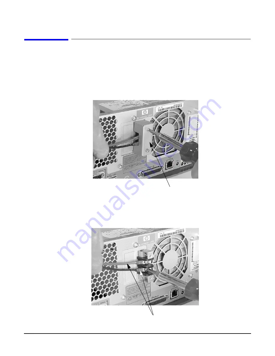
Remove the DC connector cap located on the back side of your workstation. See Figure B-2.

Figure B-2

Removing the DC Connector Cap

2.

Disconnect the power source cables from the system as stated in the WARNING at the beginning
of this chapter. See Figure B-3

Figure B-3

Disconnecting the DC Power Source

DC Connector Cap

Power Source Cables

Содержание b2600

Страница 1: ...Parts Removal and Replacement Guide HP B2600 Workstations Manufacturing Part Number A6070 90011 Edition E0601 ...

Страница 2: ... information that is protected by copyright All rights are reserved No part of this document may be photocopied reproduced or translated to another language without the prior written consent of Hewlett Packard Company UNIX is a registered trademark in the United States and other countries licensed exclusively through X Open Company Limited Copyright 1980 1984 AT T Inc Copyright 1979 1980 1983 The ...

Страница 3: ...and PCI Backplane Board 28 Replacing the PCI Cage I O Card and PCI Backplane Board 33 Removing the Hard Disk Drive s 37 Replacing the Hard Disk Drive s 38 Removing the Liquid Crystal Display LCD Module 40 Replacing the Liquid Crystal Display LCD Module 41 Removing the AC or DC Power Supply 42 Replacing the AC or DC Power Supply 44 Removing the System Board 46 Replacing the System Board 48 Removing...

Страница 4: ...gulation on Noise Declaration for Machines 75 B DC Power Supply DC Power Supply Considerations 78 Connecting Wires 78 Grounding Your Workstation 78 Location for Your DC Source and Workstation s 78 Removing the DC Power Supply 79 Replacing the DC Power Supply 82 C Remove Replace DAT Drives Removing the DAT Drive 86 Removing the SCSI Cable 89 Replacing the DAT Drive 91 Replacing the SCSI Cable 94 D ...

Страница 5: ...Contents 5 Replacing the SCSI Cable 107 ...

Страница 6: ...6 Contents ...

Страница 7: ... terms and conditions For more information please go to this web site www hp com workstations support Related Manuals The following documents are also a part of your HP B2600 document set Installation Poster for the HP B2600 Workstation Getting Started Guide for the HP B2600 Workstation Technical Reference for the HP B2600 Workstation For more information refer to the following documents Common De...

Страница 8: ...harge ESD Precautions Electrostatic charges can damage the integrated circuits on printed circuit boards To prevent such damage from occurring observe the following precautions during board unpacking and installation Work on a static free mat Wear a static strap to ensure that any accumulated electrostatic charge is discharged from your body to ground Create a common ground for the equipment you a...

Страница 9: ...9 1 Remove Replace System Components This chapter discusses the removal and replacement of system components for the HP B2600 workstations ...

Страница 10: ...of the installation and removal procedures in this chapter you must power off the workstation and unplug the workstation power cord from the AC power outlet For DC power disconnect power from the source before connecting power to the product or before accessing the product s power terminals For more details see the DC Power Supply appendix NOTE To maintain FCC EMI compliance verify that all covers...

Страница 11: ...or replace system upgrades for example hard disk drives Light duty flat blade screwdriver with 6 inch 150 mm blade Number 2 Phillips screwdriver with 6 inch 150mm blade T 10 and T 15 Torx driver ESD equipment see the Electrostatic Discharge ESD Precautions section later in this chapter for detailed information ...

Страница 12: ...llow the procedures for replacing the particular component in this chapter Electrostatic Discharge ESD Precautions To prevent damage to the HP B2600 workstation observe all of the following ESD precautions while performing the system upgrade procedures Work on a static free mat Wear a static strap to ensure that any accumulated electrostatic charge is discharged from your body to ground Create a c...

Страница 13: ...heral devices 2 Unplug the workstation power cord and all peripheral devices from AC power outlets If you are using a DC power source see Appendix B 3 Attach the static grounding wrist strap by following the instructions on the package Attach the sticky end of the wrist strap to bare metal on the rear panel of the workstation NOTE To make access to the internal components easier you may want to pl...

Страница 14: ...omponents of your system Removing the Front Bezel and Top Cover 1 Turn your workstation off and unplug it 2 Lay your workstation on a soft anti static surface with the HP logo text in the upright position 3 Press in on both release buttons found on the ends of the bezel and pull outward from the workstation to remove it Next unscrew the captive screws and pull forward on the cover and lift it off ...

Страница 15: ...ave completed the necessary component upgrades to your workstation you need to replace the top cover and bezel on you workstation Replacing the Front Bezel and Top Cover 1 Slide the top cover back on the workstation and secure it by screwing in the captive screws 2 Next push the bezel in place on the front of the workstation See Figure 1 2 Figure 1 2 Front Bezel and Top Cover Replacement Bezel Rel...

Страница 16: ...slots Here is the procedure for removing DIMM cards from your workstation 1 Complete the procedure in the section Removing the Front Bezel and Top Cover found in this chapter 2 Press downward on the tabs that are located on both ends of the memory card slots See Figure 1 3 Figure 1 3 Pressing Down on the Memory Slot Tabs 3 Grasp both edges of the DIMM card and lift it out of the memory slot See Fi...

Страница 17: ...HP B2600 workstation has four memory slots labeled SL0 SL1 SL2and SL3 SL0 is the slot closest to the workstation s chassis You can mix 256MB 512MB and 1GB memory cards in the memory slots but you must install them using the memory sequence shown in Figure 1 5 Figure 1 5 Memory Loading Sequence in the HP B2600 ...

Страница 18: ...ing DIMM cards in your workstation 1 Remove the current DIMM s if you have not already done this Otherwise skip this step To remove the current DIMM s follow the procedure in the section Removing Memory DIMMs found in this chapter 2 Determine the appropriate memory slot s for your DIMM card s See Figure 1 6 You can mix 256MB 512MB and 1GB memory cards in the memory slots but you must install them ...

Страница 19: ...r found in this chapter 5 Connect and turn on the power to your system 6 Determine that your memory installation was successful by executing the sam command as root When the System Administration Manager window appears select the System Properties icon In the new window that appears select the Memory tab The next window that appears will tell you how much memory you have available If the amount of...

Страница 20: ... latch release See Figure 1 8 Figure 1 8 Disconnecting the CD Drive Control Cable 3 Disconnect the audio extender cable and the CD drive audio cable by pressing in on the audio extender cable s latch release See Figure 1 9 Also lift up on the PCI cage audio retainer tabs to remove the audio cable from the PCI cage Note that you can skip this section if your workstation does not have an audio card ...

Страница 21: ...the raised portion of the back cover This will cause the retainer snaps to be remove from their slots on the CD drive bay See Figure 1 11 Also note the manner in which the audio power and control cables were neatly fed through the raised opening in the CD drive bay s back cover Figure 1 11 Removing the CD Drive Bay s Back Cover CD Drive CD Drive Retainer Clip CD Drive Retainer Clip CD Drive Bay CD...

Страница 22: ... is present See Figure 1 12 Note that these cables are keyed for easy replacement Figure 1 12 Disconnecting the CD Drive s Cables 7 Unscrew the four CD drive mounting screws located on both sides of the CD drive bay See Figure 1 13 Figure 1 13 Unscrew the Four CD Drive Mounting Screws Audio Cable Control Cable Power Cable Mounting Screws Mounting Screws CD Drive Bay ...

Страница 23: ...System Components Removing Replacing System Components 8 Slide the CD drive out of the CD drive bay See Figure 1 14 Figure 1 14 CD Drive Removed from the CD Drive Bay CD Drive Bay Mounting Screw Holes CD Drive Mounting Screw Holes ...

Страница 24: ...he procedure in the section Removing the CD Drive found in this chapter 2 Slide the CD drive into the CD drive bay See Figure 1 15 Figure 1 15 Slide the CD Drive into the CD Drive Bay 3 Screw the four CD drive mounting screws into their threaded holes located on both sides of the CD drive bay See Figure 1 16 Figure 1 16 Screw in the Four CD Drive Mounting Screws CD Drive Bay Mounting Screw Holes C...

Страница 25: ...nserting the hinge tabs located on the CD drive bay into their slots on the CD drive bay s back cover Next rotate the back cover toward the CD drive bay until the retainer snaps are in place See Figure 1 18 Also note the manner in which the audio power and control cables were neatly fed through the raised opening in the CD drive bay s back cover Figure 1 18 Replacing the CD Drive Bay s Back Cover ...

Страница 26: ...gure 1 19 Figure 1 19 Replacing the CD Drive Bay and CD Drive 7 Connect the CD drive power cable by pushing it into its connector on the system board and connect the control cable by pushing it into its connector on the system board See Figure 1 20 Note that the connectors are keyed Figure 1 20 Connecting the CD Drive Power and Control Cables CD Drive CD Drive Retainer Clip CD Drive Retainer Clip ...

Страница 27: ...on Replacing the Front Bezel and Top Cover found in this chapter 10 Connect and turn on the power to your system 11 Determine that your CD drive replacement was successful by executing the sam command as root When the System Administration Manager window appears double click the Disk and File System icon and in the window that appears double click the Disk Devices icon In the next window that appe...

Страница 28: ...e in the section Removing the Front Bezel and Top Cover found in this chapter 2 Complete the procedure in the section Removing the CD Drive steps 1 through 3 in this chapter Removing the DAT Drive steps 1 through 5 in Appendix C or Removing the Flexible Disk Drive steps 1 through 5 in Appendix D 3 Lift up on the PCI cage handle the CD DAT or flexible disk drives must be removed See Figure 1 22 Fig...

Страница 29: ... have removed the PCI cage from the system 1 Set the PCI cage on an anti static surface and remove the PCI cage cover See Figure 1 24 Figure 1 24 Removing the PCI Cage Cover 2 Unscrew the I O card s bulkhead screw Torx T 15 screw See Figure 1 25 Figure 1 25 Unscrewing the I O Card s Bulkhead Screw PCI Cage Cover Bulkhead Screw ...

Страница 30: ...re 1 26 Figure 1 26 Removing the I O Card from Its PCI Slot 4 Place the I O card on an anti static surface to protect it from any possible electro static discharge PCI Backplane Board Removal Once you have removed the PCI cage from the system and removed all of the I O cards from the PCI cage you are ready to remove the PCI backplane board 1 Unscrew the three T 15 Torx screws See Figure 1 27 Figur...

Страница 31: ...PCI backplane board has two elongated slots cut in it that allow the card to slide in grooves located on the top of two PCI cage standoffs The PCI backplane board will stop sliding when it reaches the opposite end of the elongated slot At this point the slot has been enlarged to allow you to lift the PCI backplane board out of the PCI cage Figure 1 28 Removing the PCI Backplane Board PCI Cage Stan...

Страница 32: ...r To do this follow the procedure in this section 1 Push the card guide forward with your thumb in the direction of the large arrow and at the same time apply downward pressure See Figure 1 29 Figure 1 29 Pushing the Card Guide Forward and Down 2 Remove the card guide from the PCI cover See Figure 1 30 Note that after you have completed step 1 the card guide will fall through the card guide slot F...

Страница 33: ...he procedure in the section Removing the CD Drive steps 1 through 3 in this chapter Removing the DAT Drive steps 1 through 5 in Appendix C or Removing the Flexible Disk Drive steps 1 through 5 in Appendix D 2 Slide the PCI backplane board onto the PCI cage s standoffs See Figure 1 31 Note that the PCI backplane board has two elongated slots cut in it that allow the card to slide in grooves located...

Страница 34: ...rocedure in the section PCI Backplane Board Replacement found in this chapter 2 Remove the I O card from its anti static bag which protects it from any possible electro static discharge 3 Grasp the I O card s bulkhead and the back edge and insert it into its PCI slot See Figure 1 33 Figure 1 33 Inserting the I O Card into its PCI Slot 4 Screw in the I O card s bulkhead screw to secure it in its PC...

Страница 35: ...cedure in the section I O Card Replacement found in this chapter 2 Push down on the PCI cage handle and on the back of the PCI cage Next rotate the PCI cage handle downward This will secure the PCI cage in the workstation See Figure 1 36 Figure 1 36 Placing the PCI Cage into the Workstation 3 Complete the procedure in the section Removing the CD Drive steps 1 through 3 in this chapter Removing the...

Страница 36: ... PCI card guide that has been removed from your PCI cage cover To replace a PCI card guide follow this procedure 1 Locate the front of the card guide slot and the card guide lip See Figure 1 37 Figure 1 37 Pushing the Card Guide Forward and Down 2 Insert the card guide from the bottom side of the PCI cage cover place the card guide lip against the front part of the card guide slot and push inward ...

Страница 37: ...See Figure 1 39 Figure 1 39 Removing the Hard Disk Drive and Its Mounting Bracket 4 Unscrew the four hard disk drive mounting screws and pull the hard disk drive out of the hard disk drive bracket See Figure 1 40 Note that for installation purposes there are four mounting screws located on the side of the unused hard disk drive bracket Figure 1 40 Removing the Hard Disk Drive from the Hard Disk Dr...

Страница 38: ... disk drive into the hard disk drive bracket and align the holes in the disk drive bracket with the threaded holes in the hard disk drive Next screw in the four mounting screws See Figure 1 41 Note that for installation purposes there are four mounting screws located on the side of the unused hard disk drive bracket Figure 1 41 Installing the Hard Disk Drive into the Hard Disk Drive Bracket 4 Gras...

Страница 39: ...s chapter 7 Complete the procedure in the section Replacing the Front Bezel and Top Cover found in this chapter 8 Connect and turn on the power to your system 9 Determine that your hard disk drive replacement was successful by executing the sam command as root When the System Administration Manager window appears double click the Disk and File System icon and in the window that appears double clic...

Страница 40: ... the section Removing the Front Bezel and Top Cover found in this chapter 2 Disconnect the LCD control cable See Figure 1 43 Figure 1 43 Disconnecting the LCD Control Cable 3 Press inward on the right side of the LCD s plastic retainer with a screwdriver and pull outward on this same side See Figure 1 44 This will remove the LCD module Figure 1 44 Removing the LCD Module LCD Control Cable LCD Conn...

Страница 41: ...Connect the LCD control cable connector to the LCD connector See Figure 1 46 Figure 1 46 Connection the LCD Control Cable Connector 4 Complete the procedure in the section Replacing the Front Bezel and Top Cover found in this chapter 5 Connect and turn on the power to your system 6 Determine that your LCD Module replacement was successful by looking at the LCD and noticing if the LCD lights up and...

Страница 42: ...the AC power supply follow this procedure 1 Unplug the power cord from the system as stated in the WARNING at the beginning of this chapter 2 Complete the procedure in the section Removing the Front Bezel and Top Cover found in this chapter 3 Disconnect the power supply cables from the system board by pressing in on the latch releases on the connectors and pulling outward See Figure 1 47 Figure 1 ...

Страница 43: ...le you are unscrewing the mounting screws Figure 1 48 Unscrewing the Four Power Supply Mounting Screws 5 Remove the AC power supply from the system To do this you will have to slide the support arm out of its slot See Figure 1 49 Note that there is a component heat sink located on the system board near the back of the power supply that can be damaged if you are not careful when removing the power ...

Страница 44: ...ne this Otherwise skip this step To remove the AC power supply follow the procedure in the section Removing the AC or DC Power Supply found in this chapter 2 Replace the AC power supply in the workstation To do this you will have to slide the power supply s support arm into its slot on the system divider panel See Figure 1 50 Figure 1 50 Replacing the AC Power Supply 3 Align the four threaded scre...

Страница 45: ...n the power to your system 7 Determine that your AC power supply replacement was successful by observing to see if the workstation s LCD lights up and the CDE login screen appears in your workstation s display If your workstation s LCD does not light up and the CDE login screen does not appear repeat this procedure If your workstation s LCD still does not light up and the CDE login screen does not...

Страница 46: ...chapter 4 Complete the procedure in the section Removing the AC or DC Power Supply found in this chapter 5 Disconnect the two fan power connectors from the system board by pressing in on the latch retainers and pulling outward on the connector The LCD connector must also be disconnect from the system board by pressing down on its latch retainers and pulling outward on the connector Next unscrew th...

Страница 47: ...the system board s turbo cooler heatsink and handle to lift it out of the workstation The system board must be angled when removing it from the workstation such that the DIMM edge of the system board is two to three inches higher than the turbo cooler heatsink edge This will prevent the system board components from catching on the system divider panel See Figure 1 56 Figure 1 56 Lifting the System...

Страница 48: ...es higher than the turbo cooler heatsink edge This will prevent the system board components from catching on the system divider panel See Figure 1 57 Figure 1 57 Placing the System Board in the Workstation 3 Grasp the system board by the microprocessor s turbo cooler heatsink and the handle located on the back edge of the system board and slide the system board toward the back of the workstation i...

Страница 49: ...nting screws See Figure 1 60 Figure 1 60 Replacing the Internal System Board Mounting Screws 6 Complete the procedure in the section Replacing the AC or DC Power Supply steps 2 through 4 found in this chapter 7 Complete the procedure in the section Replacing the Hard Disk Drive s steps 3 through 4 found in this chapter 8 Complete the procedure in the section PCI Cage Replacement step 2 found in th...

Страница 50: ...ystem 12 Determine that your system board replacement was successful by observing to see if the workstation s LCD lights up and the CDE login screen appears in your workstation s display If your workstation s LCD does not light up and the CDE login screen does not appear repeat this procedure If your workstation s LCD still does not light up and the CDE login screen does not appear contact your lo...

Страница 51: ...g too slow or stopped The fan error for a stopped fan is D01n and the fan error for a slow fan is D02n where n is the number of the fan with the error See Table 1 1 Figure 1 61 System and PCI Fan Areas Table 1 1 System Area and PCI area Fan Numbers Fan Number Description 1 Power Supply Fan 2 Right System Area Fan as you face the system s front 3 Left System Area Fan as you face the system s front ...

Страница 52: ...dure in the section Removing the Liquid Crystal Display found in this chapter 3 Unscrew the two LCD connector screws and remove the LCD connector from its opening in the chassis See Figure 1 62 Figure 1 62 Removing the LCD Connector 4 Disconnect the two fan module power cables in the system area from the system board See Figure 1 63 Figure 1 63 Disconnecting the Fan Module Power Cables for the Sys...

Страница 53: ...unting Screw 6 Remove the fan module from the workstation by tilting it back away from the workstation chassis and lifting it out of the three fan module slots on the front part of the workstation s chassis See Figure 1 65 Figure 1 65 Removing the System Area Fan Module Fan Module Mounting Screw Fan Module Fan Module Mounting Tabs Fan Module Tab Slots Fan Module Mounting Tab ...

Страница 54: ...he DAT Drive steps 1 through 5 in Appendix C or Removing the Flexible Disk Drive steps 1 through 5 in Appendix D 3 Disconnect the two fan module power cables from the system board by pressing in on the latch retainer of each connector and pulling outward on the connector See Figure 1 66 Figure 1 66 Disconnecting the Fan Module Power Cables 4 Remove the fan module mounting screw for the PCI area Se...

Страница 55: ...he fan module from the workstation by tilting it back away from the workstation chassis and lifting it out of the three fan module slots on the front part of the workstation chassis See Figure 1 68 Figure 1 68 Removing the PCI Area Fan Module Fan Module Slots Fan Module Tabs Fan Module PCI Area ...

Страница 56: ...ng too slow or stopped The fan error for a stopped fan is D01n and the fan error for a slow fan is D02n where n is the number of the fan with the error See Table 1 2 Figure 1 69 System and PCI Fan Areas Table 1 2 System Area and PCI area Fan Numbers Fan Number Description 1 Power Supply Fan 2 Right System Area Fan as you face the system s front 3 Left System Area Fan as you face the system s front...

Страница 57: ...chapter 2 Replace the fan module in the workstation by tilting it back away from the workstation chassis and inserting the three fan module mounting tabs into their slots See Figure 1 70 Figure 1 70 Replacing the System Area Fan Module 3 Align the fan module mounting screw hole in the chassis with the threaded fan module mounting screw hole and screw in the mounting screw See Figure 1 71 Figure 1 ...

Страница 58: ...mplete the procedure in the section Replacing the Liquid Crystal Display found in this chapter 7 Complete the procedure in the section Replacing the Front Bezel and Top Cover found in this chapter 8 Connect and turn on the power to your system 9 Determine that your system area fan module replacement was successful by checking the workstation s LCD for fan error messages If LCD fan error messages a...

Страница 59: ...dule Removal found in this chapter 2 Replace the fan module in the workstation by tilting it back away from the workstation chassis and inserting the three fan module tabs into their slots See Figure 1 74 Figure 1 74 Replacing the PCI Area Fan Module 3 Align the fan module mounting screw hole in the chassis with the threaded fan module mounting screw hole and screw in the mounting screw See Figure...

Страница 60: ...ive steps 2 through 7 in Appendix C or Replacing the Flexible Disk Drive steps 2 through 9 in Appendix D 6 Complete the procedure in the section Replacing the Front Bezel and Top Cover found in this chapter 7 Connect and turn on the power to your system 8 Determine that your PCI area fan module replacement was successful by checking the workstation s LCD for fan error messages If LCD fan error mes...

Страница 61: ...CD Drive steps 1 through 3 in this chapter Removing the DAT Drive steps 1 through 5 in Appendix C or Removing the Flexible Disk Drive steps 1 through 5 in Appendix D 2 Complete the procedure in the section Removing the PCI Cage I O Card and PCI Backplane Board found in this chapter 3 Determine that the audio cable has been removed This step should have been performed when the CD drive was removed ...

Страница 62: ...n the cable Figure 1 78 Remove the PCI Cage Cover and the Audio Extender Cable 5 Unscrew the bulkhead screw and remove the audio card See Figure 1 79 Figure 1 79 Remove the PCI Card Bulkhead Screw and Audio Card 6 Replace the bulkhead blank in the opening for slot one of the PCI cage and screw in the bulkhead screw for the bulkhead blank See Figure 1 80 Figure 1 80 Replace the Bulkhead Blank in th...

Страница 63: ...e board 1 Remove the audio card if you have not already done this Otherwise skip this step To remove the audio card follow the procedure in the section Removing the Audio Card found in this chapter 2 Remove the bulkhead blank from slot one of the PCI cage You will have to unscrew its bulkhead screw to remove it See Figure 1 81 Figure 1 81 Remove the Bulkhead Blank from the PCI Cage 3 Remove the au...

Страница 64: ...card bulkhead screw into the PCI cage See Figure 1 83 Figure 1 83 Secure the Audio Card in Slot 1 5 Connect the audio cable extender and replace the PCI cage cover on the PCI cage See Figure 1 84 Figure 1 84 Replace the Audio Extender Cable and the PCI Cage Cover PCI Card Slots Audio Card Bulkhead Screw Audio Cable Extender PCI Cage Cover ...

Страница 65: ...ure 1 85 Insert the PCI Cage into the Workstation 7 Connect the audio cable supplied with the audio card to the CD drive See Figure 1 86 Figure 1 86 Connect the Audio Cable to the CD Drive 8 Dress the cables that run under the back cover of the CD drive bay to avoid pinching PCI Cage Audio Cable Extender Audio Cable CD Drive CD Drive Back Cover ...

Страница 66: ... Insert the CD Drive into the Workstation and Connect Cables 10 Replace the workstations top cover and front bezel To do this read the section Replacing the Front Bezel and Top Cover found in this chapter 11 Determine that your audio card replacement was successful To do this read the section Using Your Audio Card Optional in Chapter 1 of the Getting Started Guide for the HP B2600 workstation Rais...

Страница 67: ... from your local HP Sales Representative Next follow this procedure 1 Press in on the release buttons located on both ends of the bezel to remove it See Figure 1 89 Figure 1 89 Front Bezel Removal 2 Remove the top and bottom plastic covers from the system by lifting up on the rear of the covers and pulling toward you Note that there are two plastic ridges located beneath the top and bottom covers ...

Страница 68: ...e System Chassis 3 Connect the end caps onto the front bezel by placing the retainer latches in their appropriate slots and rotating the end caps in place See Figure 1 92 Figure 1 92 Connecting the End Caps Onto the Front Bezel 4 Push the bezel with its end caps onto the front of the system You will feel it snap in Plastic Cover Locks Slots for the Cover Locks System Chassis Plastic Cover Retainer...

Страница 69: ...low this procedure A Turn on the system and press the Tab key until the select display message appears You should select the display frequency and resolution that are best for you B Stop the boot process by pressing any key before the ten second limit This gets you to the bch Main Menu You will only need to do this if you have autoboot turned on otherwise the system stops at the bch Main Menu When...

Страница 70: ...low this procedure 1 Unplug the workstation and reverse the procedure in the section Converting Your Desktop System to a Rack Mount System in this chapter You will need to complete steps 4 through 1 respectively Note that step 4 requires the use of the rack mount instructions that came with your desktop kit 2 Complete step 5 in the section Converting Your Desktop System to a Rack Mount System in t...

Страница 71: ...71 A Regulatory Statements This Appendix contains electromagnetic compatibility information and optical and acoustical statements ...

Страница 72: ...72 AppendixA Regulatory Statements Declaration of Conformity according to ISO IEC Guide 22 and EN 45014 ...

Страница 73: ...stalled and used in accordance with the instruction manual may cause harmful interference to radio communications Operation of this equipment in a residential area is likely to cause harmful interference in which case the user will be required to correct the interference at his own expense Operation of this device is subject to the following conditions This device may not cause harmful interferenc...

Страница 74: ...74 AppendixA Regulatory Statements Electromagnetic Compatibility VCCI Statement for Class A Products Korea RRL Statement for Class A Product Taiwan Class A Warning ...

Страница 75: ...d Human Services DHHS Radiation Performance Standard according to the Radiation Control for Health and Safety Act of 1968 This means that the mass storage system does not product hazardous laser radiation Because laser light emitted inside the mass storage system is completely confined within protective housings and external covers the laser beam cannot escape from the machine during any phase of ...

Страница 76: ...76 AppendixA Regulatory Statements Optical and Acoustical Statements ...

Страница 77: ...ply Note that the DC power supply allows you to set up your computer so that it is always on and ready for use Please keep in mind that this appendix should only be used by service trained personnel that are familiar with hazards associated with connecting equipment to a centralized DC power source ...

Страница 78: ...le of causing serious burns and arcing that can produce molten metal Connecting Wires The wires used to make all grounding and electrical connections to your workstation s should be a minimum of 18 AWG Note that the electrical power connectors to the workstation s must use insulated crimp on lugs This will prevent the connectors from shorting to the chassis Grounding Your Workstation A separate wi...

Страница 79: ...used to replace the DC power supply The following procedure explains how to remove your DC power supply 1 Remove the DC connector cap located on the back side of your workstation See Figure B 2 Figure B 2 Removing the DC Connector Cap 2 Disconnect the power source cables from the system as stated in the WARNING at the beginning of this chapter See Figure B 3 Figure B 3 Disconnecting the DC Power S...

Страница 80: ...four power supply mounting screws located on the back of the system See Figure B 5 Note that there is a power supply support arm that fits into a slot on the system divider panel This support arm prevents the supply from falling onto the system board while you are unscrewing the mounting screws Figure B 5 Unscrewing the Four Power Supply Mounting Screws Power Supply Cables Power Supply System Boar...

Страница 81: ...you will have to slide the support arm out of its slot See Figure B 6 Note that there is a component heat sink located on the system board near the back of the power supply that can be damaged if you are not careful when removing the power supply See Figure B 4 Figure B 6 Removing the DC Power Supply DC Power Supply ...

Страница 82: ...To do this you will have to slide the support arm into its slot See Figure B 7 Note that there is a component heat sink located on the system board near the back of the power supply that can be damaged if you are not careful when replacing the power supply See Figure B 7 Figure B 7 Replacing the DC Power Supply 3 Align the four power supply mounting screws holes on the chassis with the four thread...

Страница 83: ... 9 Connect the Power Supply Cables 5 Connect the power source cables onto their connectors on the back of the workstation s power supply Please pay attention to the WARNING in the section DC Power Supply Considerations found in this appendix See Figure B 10 Figure B 10 Disconnecting the DC Power Source Power Supply Cables Power Supply System Board Component Heat Sink Power Source Cables ...

Страница 84: ... this chapter 8 Connect and turn on the power to your system 9 Determine that your DC power supply replacement was successful by observing to see if the workstation s LCD lights up and the CDE login screen appears in your workstation s display If your workstation s LCD does not light up and the CDE login screen does not appear repeat this procedure If your workstation s LCD still does not light up...

Страница 85: ...ve Replace DAT Drives The HP B2600 workstation supports a DAT drive You will have to check with your local HP Sales Representative if you plan to purchase one This chapter explains how to remove and replace this DAT drive ...

Страница 86: ... Bezel and Top Cover found in Chapter 1 2 Disconnect the DAT drive power cable from the system board by pressing in on the connector s latch release See Figure C 1 Figure C 1 Disconnecting the DAT Drive Power Cable 3 Remove the DAT drive and DAT drive bay from the workstation by pressing in on both DAT drive retainer clips and pull outward See Figure C 2 Figure C 2 Remove the DAT Drive and DAT Dri...

Страница 87: ...Figure C 3 Figure C 3 Removing the DAT Drive Bay and DAT Drive 5 Remove the DAT drive bay s back cover Note that this back cover snaps off of the DAT drive bay See Figure C 4 Figure C 4 Removing the DAT Drive Bay s Back Cover Mounting Screws Mounting Screws SCSI Cable DAT Drive Bay DAT Drive DAT Drive Bay s Back Cover DAT Drive Bay SCSI Terminator ...

Страница 88: ...ed for easy replacement Figure C 5 Disconnecting the DAT Drive s Cables 7 Unscrew the four bracket mounting screws from the DAT drive and remove the DAT drive s two brackets See Figure C 6 Figure C 6 Unscrew the Four DAT Drive Bracket Mounting Screws DAT Drive Power Cable SCSI Cable DAT Drive Bay SCSI Terminator Bracket Mounting Screws Bracket Mounting Screws DAT Drive Bracket DAT Drive Bracket DA...

Страница 89: ...ot 4 of the PCI cage The SCSI cable is long enough to allow you to run it through the DAT drive bay and out its front This makes it easy for you to connect your power and SCSI cable connectors to the DAT drive device The connectors on both ends of the SCSI cable are keyed to allow for proper pin connection To remove the SCSI card and cable follow this procedure 1 Complete the procedure in the sect...

Страница 90: ... inside the PCI cage and observe the SCSI cable and how it is folded See Figure C 8 Next disconnect the SCSI cables connector from the SCSI card and note the connection used on the component side of the SCSI card See Figure C 8 Figure C 8 Disconnection the SCSI Cable SCSI Card SCSI Cable Connector Folded SCSI Cable ...

Страница 91: ...r screw holes with the threaded screw holes of the DAT drive and screw in the four bracket mounting screws as shown in Figure C 9 Figure C 9 Replace the DAT Drive Bracket on the DAT Drive 3 Connect the DAT drive power and SCSI cables to their connectors located on the back side of the DAT drive and slide the DAT drive into the DAT drive bay See Figure C 10 To connect the SCSI and power cables you ...

Страница 92: ...raised opening in the DAT drive bay s back cover to avoid pinching them Figure C 11 Replacing the DAT Drive Bay s Back Cover 5 Align the DAT drive bay s mounting screw holes with the threaded holes on both sides of the DAT drive and screw in the four mounting screws See Figure C 12 Figure C 12 Removing the DAT Drive Bay and DAT Drive DAT Drive Bay s Back Cover DAT Drive Bay SCSI Terminator Mountin...

Страница 93: ...e the procedure in the section Replacing the Front Bezel and Top Cover found in Chapter 1 9 Connect and turn on the power to your system 10 Determine that your DAT drive replacement was successful by executing the sam command as root When the System Administration Manager window appears double click the Disk and File System icon and in the window that appears double click the Disk Devices icon In ...

Страница 94: ...enough to allow you to run it through the DAT drive bay and out its front This makes it easy for you to connect your power and SCSI cable connectors to the DAT drive device The connectors on both ends of the SCSI cable are keyed to allow for proper pin connection To replace the SCSI card and cable follow this procedure 1 Complete the procedures in the section Removing the DAT Drive steps 1 through...

Страница 95: ... SCSI cable over the exposed edges of the I O cards as shown in Figure C 16 Grasp hold of the PCI cage handle and install the PCI cage in the workstation Figure C 16 Routing the SCSI Cable and Installing the PCI Cage PCI Cage Handle PCI Cage SCSI Cable PCI Cage Cover I O Cards ...

Страница 96: ...Appendix C Remove Replace DAT Drives Replacing the DAT Drive 96 ...

Страница 97: ...ible Disk Drives The HP B2600 workstation supports a flexible disk drive You will have to check with your local HP Sales Representative if you plan to purchase one This chapter explains how to remove and replace this flexible disk drive ...

Страница 98: ... found in Chapter 1 2 Disconnect the flexible disk drive power cable from the system board by pressing in on the power cable connector s latch release See Figure D 1 Figure D 1 Disconnecting the Flexible Disk Drive Power Cable 3 Remove the flexible disk drive and flexible disk drive bay area from the workstation by pressing in on both flexible disk drive retainer clips and pull outward See Figure ...

Страница 99: ...lifting up on the raised portion of the back cover This will cause the retainer snaps to be remove from their slots on the flexible disk drive bay See Figure D 4 Also note the manner in which the audio power and control cables were neatly fed through the raised opening in the flexible disk drive bay s back cover Figure D 4 Removing the Flexible Disk Drive Bay s Back Cover Mounting Screws Mounting ...

Страница 100: ...ight side of the flexible disk drive s SCSI connector as viewed in Figure D 5 Figure D 5 Disconnecting the Flexible Disk Drive s Cables 7 Unscrew the flexible disk drive s bezel mounting screws and remove the bezel by rotating it outward from the flexible disk drive s bracket See Figure D 6 Figure D 6 Unscrewing the Flexible Disk Drive s Bezel Mounting Screws Flexible Disk Power Cable SCSI Cable F...

Страница 101: ... workstation s PCI cage however for ease of cable routing it is best to install your SCSI card in slot 4 of the PCI cage The SCSI cable is long enough to allow you to run it through the flexible disk drive bay and out its front This makes it easy for you to connect your power and SCSI cable connectors to the flexible disk drive The connectors on both ends of the SCSI cable are keyed to allow for p...

Страница 102: ...the exposed edge of the I O cards See Figure D 8 Figure D 8 Removing the PCI Cage 3 Rotate the PCI cage over so you can see the card s inside the PCI cage and observe the SCSI cable and how it is folded See Figure D 9 Next disconnect the SCSI cables connector from the SCSI card and note the connection used See Figure D 9 Figure D 9 Disconnection the SCSI Cable PCI Cage Handle PCI Cage SCSI Cable P...

Страница 103: ... in this appendix 2 Place the new flexible disk drive in the flexible disk drive bracket and screw the bracket mounting screws into the two threaded holes located on both sides of the disk drive See Figure D 10 Figure D 10 Unscrew the Four Flexible Disk Drive Mounting Screws 3 Replace the flexible disk drive bezel by rotating it inward toward the disk drive s bracket and screw in the bezel mountin...

Страница 104: ...e flexible disk drive s power and SCSI cables See Figure D 13 Note that these cables are not keyed so when you replace the SCSI cable you will need to line up the red line on the SCSI cable with the right side of the flexible disk drive s SCSI connector as viewed in Figure D 13 Figure D 13 Connecting the Flexible Disk Drive s Cables Flexible Disk Drive s Bay SCSI Cable Power Cable Flexible Disk Po...

Страница 105: ...4 Figure D 14 Screwing in the Flexible Disk Drive Bay s Mounting Screws 7 Replace the flexible disk drive bay s back cover Note that this back cover snaps onto the flexible disk drive bay See Figure D 15 Also note that the power and SCSI cables must be neatly fed through the raised opening in the DAT drive bay s back cover to avoid pinching them Figure D 15 Replacing the Flexible Disk Drive Bay s ...

Страница 106: ...Disk Drive Power Cable 10 Complete the procedure in the section Replacing the Front Bezel and Top Cover found in Chapter 1 11 Connect and turn on the power to your system 12 Determine that your DAT drive replacement was successful by executing the sam command as root When the System Administration Manager window appears double click the Disk and File System icon and in the window that appears doub...

Страница 107: ... connect your power and SCSI cable connectors to the flexible disk drive The connectors on both ends of the SCSI cable are keyed to allow for proper pin connection However the flexible disk drive s connector is not keyed and you have to align the red line on the SCSI cable with the left side as viewed from the back of the flexible disk drive of the flexible disk drive s SCSI connector To replace t...

Страница 108: ... Route the SCSI cable over the exposed edges of the I O cards as shown in Figure D 19 Grasp hold of the PCI cage handle and install the PCI cage in the workstation Figure D 19 Routing the SCSI Cable and Installing the PCI Cage PCI Cage Handle PCI Cage SCSI Cable PCI Cage Cover I O Cards ...

Отзывы: